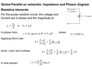
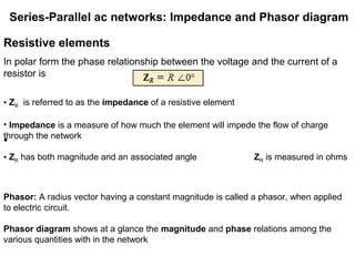
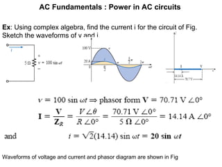
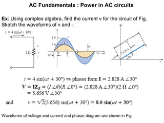
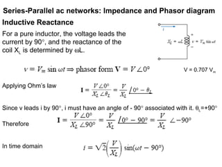
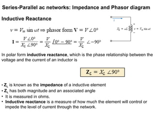
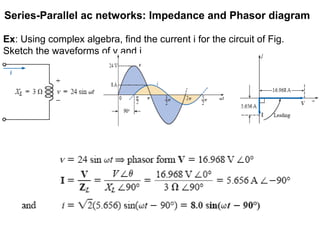
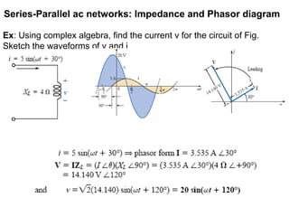
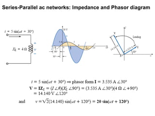
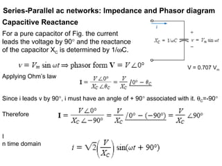
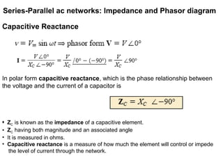
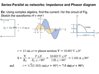
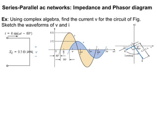
Series-Parallel
ac networks:
Impedance and
Phasor diagram
Series-Parallel ac networks: Impedance and Phasor diagram
Resistive elements
For the purely resistive circuit, the voltage and
Current are in phase and the magnitude is
In phasor form where
Applying Ohm’s law
since v and I are in phase
In time domain
V = 0.707 Vm
Series-Parallel ac networks: Impedance and Phasor diagram
Resistive elements
In polar form the phase relationship between the voltage and the current of a
resistor is
•
Phasor: A radius vector having a constant magnitude is called a phasor, when applied
to electric circuit.
Phasor diagram shows at a glance the magnitude and phase relations among the
various quantities with in the network
• ZR is referred to as the impedance of a resistive element
• Impedance is a measure of how much the element will impede the flow of charge
through the network
• ZR has both magnitude and an associated angle ZR is measured in ohms
AC Fundamentals : Power in AC circuits
Ex: Using complex algebra, find the current i for the circuit of Fig.
Sketch the waveforms of v and i.
Waveforms of voltage and current and phasor diagram are shown in Fig
AC Fundamentals : Power in AC circuits
Ex: Using complex algebra, find the current v for the circuit of Fig.
Sketch the waveforms of v and i.
Waveforms of voltage and current and phasor diagram are shown in Fig
Series-Parallel ac networks: Impedance and Phasor diagram
Inductive Reactance
For a pure inductor, the voltage leads the
current by 90°, and the reactance of the
coil XL is determined by ωL.
Applying Ohm’s law
Since v leads i by 90°, i must have an angle of - 90° associated with it. θL=+90°
Therefore
In time domain
V = 0.707 Vm
Series-Parallel ac networks: Impedance and Phasor diagram
Inductive Reactance
In polar form inductive reactance, which is the phase relationship between the
voltage and the current of an inductor is
• ZL is known as the impedance of a inductive element
• ZL has both magnitude and an associated angle
• It is measured in ohms.
• Inductive reactance is a measure of how much the element will control or
impede the level of current through the network.
Series-Parallel ac networks: Impedance and Phasor diagram
Ex: Using complex algebra, find the current i for the circuit of Fig.
Sketch the waveforms of v and i
Series-Parallel ac networks: Impedance and Phasor diagram
Ex: Using complex algebra, find the current v for the circuit of Fig.
Sketch the waveforms of v and i
Series-Parallel ac networks: Impedance and Phasor diagram
Capacitive Reactance
For a pure capacitor of Fig. the current
leads the voltage by 90° and the reactance
of the capacitor XC is determined by 1/ωC.
Applying Ohm’s law
Since i leads v by 90°, i must have an angle of + 90° associated with it. θC=-90°
Therefore
I
n time domain
V = 0.707 Vm
Series-Parallel ac networks: Impedance and Phasor diagram
Capacitive Reactance
In polar form capacitive reactance, which is the phase relationship between
the voltage and the current of a capacitor is
•• ZC is known as the impedance of a capacitive element.
• ZC having both magnitude and an associated angle
• It is measured in ohms.
• Capacitive reactance is a measure of how much the element will control or impede
the level of current through the network.
Series-Parallel ac networks: Impedance and Phasor diagram
Ex: Using complex algebra, find the current i for the circuit of Fig.
Sketch the waveforms of v and i
Series-Parallel ac networks: Impedance and Phasor diagram
Ex: Using complex algebra, find the current v for the circuit of Fig.
Sketch the waveforms of v and i

Series parallel ac networks

  • 1.
  • 2.
    Series-Parallel ac networks:Impedance and Phasor diagram Resistive elements For the purely resistive circuit, the voltage and Current are in phase and the magnitude is In phasor form where Applying Ohm’s law since v and I are in phase In time domain V = 0.707 Vm
  • 3.
    Series-Parallel ac networks:Impedance and Phasor diagram Resistive elements In polar form the phase relationship between the voltage and the current of a resistor is • Phasor: A radius vector having a constant magnitude is called a phasor, when applied to electric circuit. Phasor diagram shows at a glance the magnitude and phase relations among the various quantities with in the network • ZR is referred to as the impedance of a resistive element • Impedance is a measure of how much the element will impede the flow of charge through the network • ZR has both magnitude and an associated angle ZR is measured in ohms
  • 4.
    AC Fundamentals :Power in AC circuits Ex: Using complex algebra, find the current i for the circuit of Fig. Sketch the waveforms of v and i. Waveforms of voltage and current and phasor diagram are shown in Fig
  • 5.
    AC Fundamentals :Power in AC circuits Ex: Using complex algebra, find the current v for the circuit of Fig. Sketch the waveforms of v and i. Waveforms of voltage and current and phasor diagram are shown in Fig
  • 6.
    Series-Parallel ac networks:Impedance and Phasor diagram Inductive Reactance For a pure inductor, the voltage leads the current by 90°, and the reactance of the coil XL is determined by ωL. Applying Ohm’s law Since v leads i by 90°, i must have an angle of - 90° associated with it. θL=+90° Therefore In time domain V = 0.707 Vm
  • 7.
    Series-Parallel ac networks:Impedance and Phasor diagram Inductive Reactance In polar form inductive reactance, which is the phase relationship between the voltage and the current of an inductor is • ZL is known as the impedance of a inductive element • ZL has both magnitude and an associated angle • It is measured in ohms. • Inductive reactance is a measure of how much the element will control or impede the level of current through the network.
  • 8.
    Series-Parallel ac networks:Impedance and Phasor diagram Ex: Using complex algebra, find the current i for the circuit of Fig. Sketch the waveforms of v and i
  • 9.
    Series-Parallel ac networks:Impedance and Phasor diagram Ex: Using complex algebra, find the current v for the circuit of Fig. Sketch the waveforms of v and i
  • 10.
    Series-Parallel ac networks:Impedance and Phasor diagram
  • 11.
    Series-Parallel ac networks:Impedance and Phasor diagram Capacitive Reactance For a pure capacitor of Fig. the current leads the voltage by 90° and the reactance of the capacitor XC is determined by 1/ωC. Applying Ohm’s law Since i leads v by 90°, i must have an angle of + 90° associated with it. θC=-90° Therefore I n time domain V = 0.707 Vm
  • 12.
    Series-Parallel ac networks:Impedance and Phasor diagram Capacitive Reactance For a pure capacitor of Fig. the current leads the voltage by 90° and the reactance of the capacitor XC is determined by 1/ωC. Applying Ohm’s law Since i leads v by 90°, i must have an angle of + 90° associated with it. θC=-90° Therefore I n time domain V = 0.707 Vm
  • 13.
    Series-Parallel ac networks:Impedance and Phasor diagram Capacitive Reactance In polar form capacitive reactance, which is the phase relationship between the voltage and the current of a capacitor is •• ZC is known as the impedance of a capacitive element. • ZC having both magnitude and an associated angle • It is measured in ohms. • Capacitive reactance is a measure of how much the element will control or impede the level of current through the network.
  • 14.
    Series-Parallel ac networks:Impedance and Phasor diagram Capacitive Reactance In polar form capacitive reactance, which is the phase relationship between the voltage and the current of a capacitor is •• ZC is known as the impedance of a capacitive element. • ZC having both magnitude and an associated angle • It is measured in ohms. • Capacitive reactance is a measure of how much the element will control or impede the level of current through the network.
  • 15.
    Series-Parallel ac networks:Impedance and Phasor diagram Ex: Using complex algebra, find the current i for the circuit of Fig. Sketch the waveforms of v and i
  • 16.
    Series-Parallel ac networks:Impedance and Phasor diagram Ex: Using complex algebra, find the current v for the circuit of Fig. Sketch the waveforms of v and i