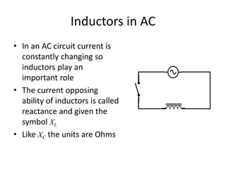
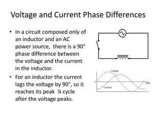
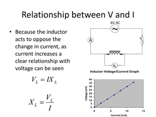
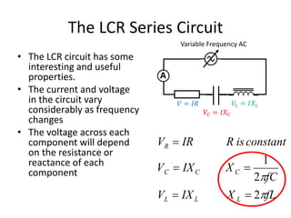
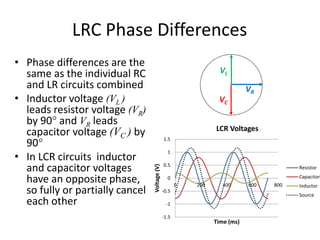
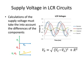
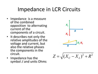
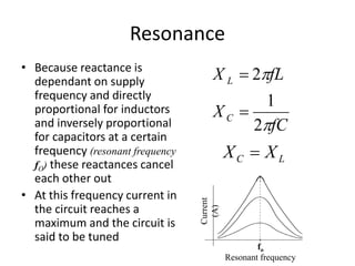
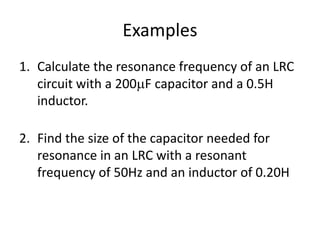
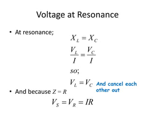
Inductors in AC 
Circuits
Inductors 
• An inductor affects a circuit 
whenever current (I) is changing. 
• The magnetic field generated by 
the inductor acts to induce an 
opposing current (Lenz’s Law). 
• The ideal inductor stores energy in 
its magnetic field which is then 
returned to the circuit as electrical 
energy, the only energy loss is from 
the resistance of the circuit.
Inductors in AC 
• In an AC circuit current is 
constantly changing so 
inductors play an 
important role 
• The current opposing 
ability of inductors is called 
reactance and given the 
symbol XL 
• Like XC the units are Ohms
Voltage and Current Phase Differences 
• In a circuit composed only of 
an inductor and an AC 
power source, there is a 90° 
phase difference between 
the voltage and the current 
in the inductor. 
• For an inductor the current 
lags the voltage by 90°, so it 
reaches its peak ¼ cycle 
after the voltage peaks.
Relationship between V and I 
• Because the inductor 
acts to oppose the 
change in current, as 
current increases a 
clear relationship with 
voltage can be seen 
Inductor Voltage/Current Graph 
40 
35 
30 
25 
20 
15 
10 
5 
0 
0 5 10 15 
Current (mA) 
Voltage (mV) 
L L V  IX 
V 
X L 
I 
L  
~ 
VL 
A 
6V AC
Examples 
1. Find the inductor voltage of an AC circuit with a 
reactance of 2.4 and a current of 0.18A 
0.43V 
2. An inductor has a voltage of 8.2V AC and a 
reactance of 54. Calculate the current of the 
circuit. 
0.15A 
3. Calculate the reactance of a circuit with an 
inductor voltage of 16V and a current of 1.2A 
13
Factors Affecting Reactance (XL ) 
• Increasing the size of the inductor (L) will induce a higher opposing 
voltage and therefore increase XL 
L X L  
• Increasing frequency increases induced current (increasing 
reactance). This is because more frequent creation and collapse of 
magnetic field produces greater opposing current 
X f L  
• The reactance of a capacitor with a supply frequency f; 
X fL X L L L  2 or 
Examples 
1. A 0.5H inductor is connected to a 6V 50Hz AC 
supply. 
a) Calculate the reactance of the inductor 
157 
b) The RMS current in the circuit 
0.038A 
2. What size inductor is needed to give an 
reactance of 25 in a 18V 60Hz circuit? 
66 mF
• VL as ¼ cycle ahead of 
resistive voltage 
• Because VL is maximum 
where VR is changing most 
(gradient steepest) 
• Note: the value of VR and 
VL are not always equal as 
in this example 
Resistor and Inductor Phase Differences 
1.5 
1 
0.5 
0 
-0.5 
-1 
-1.5 
0 200 400 600 800 
Time (ms) 
Voltage (mV) 
Resistor 
Inductor 
Phase Differences in LR Circuits 
VL 
VR
The Effect of Phase Differences in LR Circuits 
• In DC circuits the voltages 
across components in a 
circuit add up to the supply 
voltage 
• In AC Inductor/Resistor (LR) 
circuits the same does not 
appear to apply (at first 
glance) just like RC circuits 
12 
V 
VS 
100 0.50H 
VR VC 
6.4V 10 
V
The Effect of Phase Differences in LR Circuits 
• However if we consider the 
phase differences, we see 
that this is a vector problem 
VL 
~ ~ ~ 
V  V  
V 
S R L VS 
VR 
12 
V 
100 0.50H 
From 
Pythagorus; VL 
2 2 2 
C  A  
B 
2 2 
V  V  
V 
S R L VS 
VR 
VS 
VR VC 
6.4V 10 
V
The Effect of Phase Differences in LR Circuits 
2 
1.5 
1 
0.5 
0 
-0.5 
-1 
-1.5 
-2 
Supply Voltage of Resistor/Inductor 
Ciruits 
0 200 400 600 800 
Voltage (mV) 
Time (ms) 
Inductor 
Resistor 
Supply 
Voltage 
In an LR circuit; 
• At any instant 
S R L V V V 
Note the graph 
• But when considering 
the rms voltages the 
phase differences are 
important 
~ ~ ~ 
  2 2 
S R L V V V 
S R L V  V V
Exercises 
1. Find the AC supply voltage of an LR circuit where the 
resistor voltage is 3.4V and the inductor voltage is 
1.5V 
3.7V 
2. Calculate the voltage across the resistor in an AC 
circuit with a supply voltage of 8.5V and a inductor 
voltage of 2.4V 
8.2V 
3. Calculate the voltage across the inductor in an 12V AC 
circuit with a voltage of 8.5V across the resistor. 
8.5V 
4. Find the supply voltage of an 60Hz AC circuit with a 
120V across a 2k resistor and an inductor voltage of 
0.80V 
120V
Impedance 
• As with LR circuits impedance relates supply 
voltage to current. 
V IZ 
 
so; 
V 
S 
I 
S 
and 
Z 
 
• Using Pythagoras from the addition of phasors 
2 2 
L Z  R  X
Examples 
1. Calculate the impedance of an LR circuit with a 
resistance of 75 and a reactance of 15  
76  
2. An LR circuit has an impedance of 65  and has 
a resistance of 24 . What is the reactance of 
the circuit? 
60  
3. Find the resistance of an LR circuit with 25  
impedance and 12  reactance. 
22 
Inductors in DC c.f. AC 
18V DC 18V AC 50Hz 
A A 
400mH 400mH 
0.15A 
• Both circuits have the same components but behave 
quite differently because of their power supplies; 
1. Find the resistance of the resistor 
2. What assumption did you make in 1? 
3. Calculate the reactance of the circuit 
4. What is the impedance of the circuit? 
5. Calculate the current in the AC circuit
The LCR Series Circuit 
• The LCR circuit has some 
interesting and useful 
properties. 
• The current and voltage 
in the circuit vary 
considerably as frequency 
changes 
• The voltage across each 
component will depend 
on the resistance or 
reactance of each 
component 
Variable Frequency AC 
A 
R is constant 
1 
fC 
V IR 
V IX 
X 
 
  
C C 
C 
R 
2 
 
2 
V IX fL 
L L 
 
  
L 
X 
푉 = 퐼푅 
푉퐶 = 퐼푋퐶 
푉퐿 = 퐼푋퐿
LRC Phase Differences 
• Phase differences are the 
same as the individual RC 
and LR circuits combined 
• Inductor voltage (VL ) 
leads resistor voltage (VR) 
by 90 and VR leads 
capacitor voltage (VC ) by 
90 
• In LCR circuits inductor 
and capacitor voltages 
have an opposite phase, 
so fully or partially cancel 
each other 
VL 
VR 
VC 
1.5 
1 
0.5 
0 
-0.5 
-1 
-1.5 
LCR Voltages 
0 200 400 600 800 
Voltage (V) 
Time (ms) 
Resistor 
Capacitor 
Inductor 
Source
LCR Phasors 
• In most cases the L, C and R 
phasors will be different lengths 
• Most commonly voltage and 
reactance/resistor phasors are 
considered 
• In either case remember to 
calculate the differences between 
the two opposite phasors before 
calculating VS or Z 
VL 
VR 
VC 
VL-VC 
VS 
VR 
XL 
R 
XC 
XL-XC 
Z 
R 
LorC effective L C V V V 
T C L X  X  X 
or;
Supply Voltage in LCR Circuits 
• Calculations of the 
supply voltage must 
take the into account 
the differences of the 
components 
VL 
VR 
VC 
VL-VC 
VS 
1.5 
1 
0.5 
0 
-0.5 
-1 
-1.5 
LCR Voltages 
0 200 400 600 800 
푉푆 = (푉퐶−푉퐿)2 + 푅2 
Voltage (V) 
Time (ms) 
Resistor 
Capacitor 
Inductor 
Source
Examples 
1. Calculate the supply voltage of an LCR circuit 
where the capacitor voltage is 12V, the resistor 
voltage is 18V  and the inductor voltage is 6V 
19V 
2. Calculate the resistor voltage of an LCR circuit 
where the supply voltage 240V, the capacitor 
voltage is 85V and the inductor voltage is 220V 
198  
3. Find the inductor voltage of an LCR circuit where 
the supply voltage is 12V, the resistor voltage is 
9.8V and the capacitor voltage is 4.5V 
2.4V
Impedance in LCR Circuits 
Z 
2 2 Z X X R C L  (  )  
• Impedance is a measure 
of the combined 
opposition to alternating 
current of the 
components of a circuit. 
• It describes not only the 
relative amplitudes of the 
voltage and current, but 
also the relative phases 
the components in the 
circuit. 
• Impedance has the 
symbol Z and units Ohms 
XL 
R 
XC 
XL-XC 
R
Examples 
1. Calculate the impedance of an LCR circuit where 
the capacitor reactance is 25, the resistance is 
50  and the inductor reactance is 15  
51  
2. Calculate the resistance of an LCR circuit where 
the impedance 110  is capacitor reactance is 
64  and the inductor reactance is 25  
100  
3. Find the inductor reactance of an LCR circuit 
where the impedance is 120 , the resistance is 
110  and the capacitor reactance is 30  
120 
Resonance 
• Because reactance is 
dependant on supply 
frequency and directly 
proportional for inductors 
and inversely proportional 
for capacitors at a certain 
frequency (resonant frequency 
fO) these reactances cancel 
each other out 
• At this frequency current in 
the circuit reaches a 
maximum and the circuit is 
said to be tuned 
fL 
 
1 
fC 
2 
 
2 
 
 
L 
C 
X 
X 
C L X  X 
fo 
Resonant frequency 
Current 
(A)
Resonant Frequency 
• Because at resonance; 
so; 
f C 
C L X  X 
f L 
o 
o 
 
 
2 
1 
2  
LC 
fo 
2 
1 
 
Note that the resonant frequency is 
independent of the resistance
Examples 
1. Calculate the resonance frequency of an LRC 
circuit with a 200F capacitor and a 0.5H 
inductor. 
2. Find the size of the capacitor needed for 
resonance in an LRC with a resonant 
frequency of 50Hz and an inductor of 0.20H
Voltage at Resonance 
• At resonance; 
• And because Z = R 
X  
X 
L C 
V 
V 
L C 
I 
so 
 
; 
V V 
I 
 
L C 
V V IR S R   
And cancel each 
other out
Examples
Exercises 
ESA Pg 282 
Activity 16E, 16F, 16G, 16H 
ABA 
Pg 186-196

Inductors in AC Circuits

  • 1.
    Inductors in AC Circuits
  • 2.
    Inductors • Aninductor affects a circuit whenever current (I) is changing. • The magnetic field generated by the inductor acts to induce an opposing current (Lenz’s Law). • The ideal inductor stores energy in its magnetic field which is then returned to the circuit as electrical energy, the only energy loss is from the resistance of the circuit.
  • 3.
    Inductors in AC • In an AC circuit current is constantly changing so inductors play an important role • The current opposing ability of inductors is called reactance and given the symbol XL • Like XC the units are Ohms
  • 4.
    Voltage and CurrentPhase Differences • In a circuit composed only of an inductor and an AC power source, there is a 90° phase difference between the voltage and the current in the inductor. • For an inductor the current lags the voltage by 90°, so it reaches its peak ¼ cycle after the voltage peaks.
  • 5.
    Relationship between Vand I • Because the inductor acts to oppose the change in current, as current increases a clear relationship with voltage can be seen Inductor Voltage/Current Graph 40 35 30 25 20 15 10 5 0 0 5 10 15 Current (mA) Voltage (mV) L L V  IX V X L I L  ~ VL A 6V AC
  • 6.
    Examples 1. Findthe inductor voltage of an AC circuit with a reactance of 2.4 and a current of 0.18A 0.43V 2. An inductor has a voltage of 8.2V AC and a reactance of 54. Calculate the current of the circuit. 0.15A 3. Calculate the reactance of a circuit with an inductor voltage of 16V and a current of 1.2A 13
  • 8.
    Factors Affecting Reactance(XL ) • Increasing the size of the inductor (L) will induce a higher opposing voltage and therefore increase XL L X L  • Increasing frequency increases induced current (increasing reactance). This is because more frequent creation and collapse of magnetic field produces greater opposing current X f L  • The reactance of a capacitor with a supply frequency f; X fL X L L L  2 or 
  • 9.
    Examples 1. A0.5H inductor is connected to a 6V 50Hz AC supply. a) Calculate the reactance of the inductor 157 b) The RMS current in the circuit 0.038A 2. What size inductor is needed to give an reactance of 25 in a 18V 60Hz circuit? 66 mF
  • 11.
    • VL as¼ cycle ahead of resistive voltage • Because VL is maximum where VR is changing most (gradient steepest) • Note: the value of VR and VL are not always equal as in this example Resistor and Inductor Phase Differences 1.5 1 0.5 0 -0.5 -1 -1.5 0 200 400 600 800 Time (ms) Voltage (mV) Resistor Inductor Phase Differences in LR Circuits VL VR
  • 12.
    The Effect ofPhase Differences in LR Circuits • In DC circuits the voltages across components in a circuit add up to the supply voltage • In AC Inductor/Resistor (LR) circuits the same does not appear to apply (at first glance) just like RC circuits 12 V VS 100 0.50H VR VC 6.4V 10 V
  • 13.
    The Effect ofPhase Differences in LR Circuits • However if we consider the phase differences, we see that this is a vector problem VL ~ ~ ~ V  V  V S R L VS VR 12 V 100 0.50H From Pythagorus; VL 2 2 2 C  A  B 2 2 V  V  V S R L VS VR VS VR VC 6.4V 10 V
  • 14.
    The Effect ofPhase Differences in LR Circuits 2 1.5 1 0.5 0 -0.5 -1 -1.5 -2 Supply Voltage of Resistor/Inductor Ciruits 0 200 400 600 800 Voltage (mV) Time (ms) Inductor Resistor Supply Voltage In an LR circuit; • At any instant S R L V V V Note the graph • But when considering the rms voltages the phase differences are important ~ ~ ~   2 2 S R L V V V S R L V  V V
  • 15.
    Exercises 1. Findthe AC supply voltage of an LR circuit where the resistor voltage is 3.4V and the inductor voltage is 1.5V 3.7V 2. Calculate the voltage across the resistor in an AC circuit with a supply voltage of 8.5V and a inductor voltage of 2.4V 8.2V 3. Calculate the voltage across the inductor in an 12V AC circuit with a voltage of 8.5V across the resistor. 8.5V 4. Find the supply voltage of an 60Hz AC circuit with a 120V across a 2k resistor and an inductor voltage of 0.80V 120V
  • 17.
    Impedance • Aswith LR circuits impedance relates supply voltage to current. V IZ  so; V S I S and Z  • Using Pythagoras from the addition of phasors 2 2 L Z  R  X
  • 18.
    Examples 1. Calculatethe impedance of an LR circuit with a resistance of 75 and a reactance of 15  76  2. An LR circuit has an impedance of 65  and has a resistance of 24 . What is the reactance of the circuit? 60  3. Find the resistance of an LR circuit with 25  impedance and 12  reactance. 22 
  • 20.
    Inductors in DCc.f. AC 18V DC 18V AC 50Hz A A 400mH 400mH 0.15A • Both circuits have the same components but behave quite differently because of their power supplies; 1. Find the resistance of the resistor 2. What assumption did you make in 1? 3. Calculate the reactance of the circuit 4. What is the impedance of the circuit? 5. Calculate the current in the AC circuit
  • 21.
    The LCR SeriesCircuit • The LCR circuit has some interesting and useful properties. • The current and voltage in the circuit vary considerably as frequency changes • The voltage across each component will depend on the resistance or reactance of each component Variable Frequency AC A R is constant 1 fC V IR V IX X    C C C R 2  2 V IX fL L L    L X 푉 = 퐼푅 푉퐶 = 퐼푋퐶 푉퐿 = 퐼푋퐿
  • 22.
    LRC Phase Differences • Phase differences are the same as the individual RC and LR circuits combined • Inductor voltage (VL ) leads resistor voltage (VR) by 90 and VR leads capacitor voltage (VC ) by 90 • In LCR circuits inductor and capacitor voltages have an opposite phase, so fully or partially cancel each other VL VR VC 1.5 1 0.5 0 -0.5 -1 -1.5 LCR Voltages 0 200 400 600 800 Voltage (V) Time (ms) Resistor Capacitor Inductor Source
  • 23.
    LCR Phasors •In most cases the L, C and R phasors will be different lengths • Most commonly voltage and reactance/resistor phasors are considered • In either case remember to calculate the differences between the two opposite phasors before calculating VS or Z VL VR VC VL-VC VS VR XL R XC XL-XC Z R LorC effective L C V V V T C L X  X  X or;
  • 24.
    Supply Voltage inLCR Circuits • Calculations of the supply voltage must take the into account the differences of the components VL VR VC VL-VC VS 1.5 1 0.5 0 -0.5 -1 -1.5 LCR Voltages 0 200 400 600 800 푉푆 = (푉퐶−푉퐿)2 + 푅2 Voltage (V) Time (ms) Resistor Capacitor Inductor Source
  • 25.
    Examples 1. Calculatethe supply voltage of an LCR circuit where the capacitor voltage is 12V, the resistor voltage is 18V  and the inductor voltage is 6V 19V 2. Calculate the resistor voltage of an LCR circuit where the supply voltage 240V, the capacitor voltage is 85V and the inductor voltage is 220V 198  3. Find the inductor voltage of an LCR circuit where the supply voltage is 12V, the resistor voltage is 9.8V and the capacitor voltage is 4.5V 2.4V
  • 27.
    Impedance in LCRCircuits Z 2 2 Z X X R C L  (  )  • Impedance is a measure of the combined opposition to alternating current of the components of a circuit. • It describes not only the relative amplitudes of the voltage and current, but also the relative phases the components in the circuit. • Impedance has the symbol Z and units Ohms XL R XC XL-XC R
  • 28.
    Examples 1. Calculatethe impedance of an LCR circuit where the capacitor reactance is 25, the resistance is 50  and the inductor reactance is 15  51  2. Calculate the resistance of an LCR circuit where the impedance 110  is capacitor reactance is 64  and the inductor reactance is 25  100  3. Find the inductor reactance of an LCR circuit where the impedance is 120 , the resistance is 110  and the capacitor reactance is 30  120 
  • 30.
    Resonance • Becausereactance is dependant on supply frequency and directly proportional for inductors and inversely proportional for capacitors at a certain frequency (resonant frequency fO) these reactances cancel each other out • At this frequency current in the circuit reaches a maximum and the circuit is said to be tuned fL  1 fC 2  2   L C X X C L X  X fo Resonant frequency Current (A)
  • 31.
    Resonant Frequency •Because at resonance; so; f C C L X  X f L o o   2 1 2  LC fo 2 1  Note that the resonant frequency is independent of the resistance
  • 32.
    Examples 1. Calculatethe resonance frequency of an LRC circuit with a 200F capacitor and a 0.5H inductor. 2. Find the size of the capacitor needed for resonance in an LRC with a resonant frequency of 50Hz and an inductor of 0.20H
  • 33.
    Voltage at Resonance • At resonance; • And because Z = R X  X L C V V L C I so  ; V V I  L C V V IR S R   And cancel each other out
  • 34.
  • 35.
    Exercises ESA Pg282 Activity 16E, 16F, 16G, 16H ABA Pg 186-196