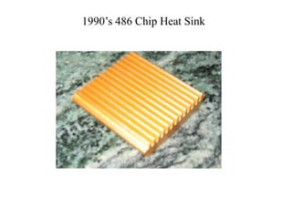
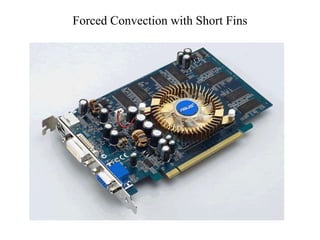
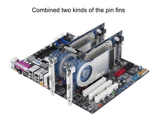
This document discusses the design of heat sinks for semiconductor devices. It describes the evolution of heat sink designs from simple uniform designs in the early 1990s to more complex designs with features like short fins, longitudinal fins, and combined pin fins to improve convection cooling. The key factors in heat sink design are thermal conductivity, cooling surface area, material and manufacturing costs. Designs must consider parameters like air temperature, velocity, duct size, and power dissipation. Optimization of factors like fin geometry, number of fins, and base thickness can improve thermal performance while meeting other constraints.
If you are working in refining or petrochemical industry, you need to learn about fired heaters. This paper talks about basic specifications of fired heaters. You can benefit by using good specifications to purchase fired heaters for your next project.
Heat-Exchanger Mechanical Engineering Power EngineeringSagar Porlekar
Increased operating temperatures and higher efficiency in gas turbines and jet engines can reduce CO2 emission, thus contributing to the prevention of global warming. To achieve this goal, it is essential to improve the properties of high temperature materials
What is heat exchanger & its Functions
Types of Heat Exchangers
Compact Heat Exchangers
Part of Fin Plate Heat Exchangers
Advantages & Disadvantages of Fin Plate Exchangers
Materials & Manufacturing
Overall Heat transfer Coefficient & Fouling Factor
LMTD Method
Effectiveness - NTU Method
A Thesis on Design Optimization of Heat Sink in Power ElectronicsIJERA Editor
The heat sinks are used in electronic systems to remove heat from the chip and effectively transfer it to the ambient. The heat sink geometry is designed by the mechanical engineers with the primary aim of reducing the thermal resistance of the heat sink for better cooling in the electronic systems. Due to the proximity of the heat sink with the ICs, the RF fields created by RF currents in the ICs/PCBs gets coupled to heat sinks. Hence, the coupled RF current can cause radiated emission. This radiated noise from the device can couple and disturb the functioning of the nearby electronic systems. Also this radiated emission from the device poses a problem to the system compliance with respect to EMI/EMC regulations. The international EMI/EMC standards require the radiated emission from the electronic devices to be kept below the specified limits. As a result the design of Heat Sink is very important factor for the efficient operation of the electronic equipment. In this project design optimization of a Heat sink in a Power amplifier is performed to reduce the weight and size .Power amplifier is electronic equipment mounted in an army vehicle. The power modules inside the amplifier generates a heat of 1440 Watts and a temperature of 140 0c.Two Heat sinks are used to dissipate the heat generated inside the equipment and maintain a temperature of less than 850c. The existing heat sink which is being used is weighing around 10.3kgs and height of 51mm; as a result the unit is very robust. The objective of my project is To design & optimize the heat sink to reduce the weight and size. The optimized heat sink should also dissipate heat generated by power modules and maintain a temperature of less than 850c inside. To achieve the design a steady state thermal analysis will be performed on the heat sink and plot the Temperature distribution on the fins. Based on the above analysis results we will increase/decrease the number of fins, thickness of fins, and height of fins to reduce the weight of the heat sink. We will perform CFD analysis of the power amplifier by mounting the optimized heat sink and plot temperature, pressure and velocity distribution in the power amplifier enclosure. Efforts are made to optimize temperature, pressure and velocity distribution in the power amplifier enclosure by reorienting the power modules in the enclosure. UNIGRAPHICS software is used for 3D modeling SOLID WORKS FLOW SIMULATION software is used for thermal and CFD analysis.
Ijri te-03-012 design and optimization of water cool condenser for central ai...Ijripublishers Ijri
Water-cooled chiller systems have typically been designed around entering condenser water temperatures of 85°F with a Optimization of Water - Cooled Chiller – Cooling Tower Combinations The warm water leaving the chilled water coils is pumped to the evaporator of the chiller, where the unwanted heat from the building is transferred by the latent heat of vaporization of the refrigerant. The compressor of the chiller then compresses the refrigerant to a higher pressure, adding the heat of compression in the process. The high pressure refrigerant then moves to the economical condenser water flow of 3.0 USGPM/ton and a 10°F denser, where the unwanted heat is rerange. In recent years, there has been considerable debate on the merits of designing around lower condenser water flow rates with a higher range in order to improve system lifecycle costs. However, two other parameters must also be considered in any analysis - approach and design wet bulb. The question to be answered is: What nominal condenser water flow rate and approach is best from a first cost standpoint as well as from a full load energy standpoint at any given wet bulb.
DESIGN AND FABRICATION OF HELICAL TUBE IN COIL TYPE HEAT EXCHANGERhemantnehete
Heat exchangers are the important engineering systems with wide variety of applications including power plants, nuclear reactors, refrigeration and air-conditioning systems, heat recovery systems, chemical processing and food industries. Helical coil configuration is very effective for heat exchangers and chemical reactors because they can accommodate a large heat transfer area in a small space, with high heat transfer coefficients. This project focus on an increase in the effectiveness of a heat exchanger and analysis of various parameters that affect the effectiveness of a heat exchanger and also deals with the performance analysis of heat exchanger by varying various parameters like number of coils, flow rate and temperature. The results of the helical tube heat exchanger are compared with the straight tube heat exchanger in both parallel and counter flow by varying parameters like temperature, flow rate of cold water and number of turns of helical coil.
Hierarchical Digital Twin of a Naval Power SystemKerry Sado
A hierarchical digital twin of a Naval DC power system has been developed and experimentally verified. Similar to other state-of-the-art digital twins, this technology creates a digital replica of the physical system executed in real-time or faster, which can modify hardware controls. However, its advantage stems from distributing computational efforts by utilizing a hierarchical structure composed of lower-level digital twin blocks and a higher-level system digital twin. Each digital twin block is associated with a physical subsystem of the hardware and communicates with a singular system digital twin, which creates a system-level response. By extracting information from each level of the hierarchy, power system controls of the hardware were reconfigured autonomously. This hierarchical digital twin development offers several advantages over other digital twins, particularly in the field of naval power systems. The hierarchical structure allows for greater computational efficiency and scalability while the ability to autonomously reconfigure hardware controls offers increased flexibility and responsiveness. The hierarchical decomposition and models utilized were well aligned with the physical twin, as indicated by the maximum deviations between the developed digital twin hierarchy and the hardware.
Overview of the fundamental roles in Hydropower generation and the components involved in wider Electrical Engineering.
This paper presents the design and construction of hydroelectric dams from the hydrologist’s survey of the valley before construction, all aspects and involved disciplines, fluid dynamics, structural engineering, generation and mains frequency regulation to the very transmission of power through the network in the United Kingdom.
Author: Robbie Edward Sayers
Collaborators and co editors: Charlie Sims and Connor Healey.
(C) 2024 Robbie E. Sayers
Cosmetic shop management system project report.pdfKamal Acharya
Buying new cosmetic products is difficult. It can even be scary for those who have sensitive skin and are prone to skin trouble. The information needed to alleviate this problem is on the back of each product, but it's thought to interpret those ingredient lists unless you have a background in chemistry.
Instead of buying and hoping for the best, we can use data science to help us predict which products may be good fits for us. It includes various function programs to do the above mentioned tasks.
Data file handling has been effectively used in the program.
The automated cosmetic shop management system should deal with the automation of general workflow and administration process of the shop. The main processes of the system focus on customer's request where the system is able to search the most appropriate products and deliver it to the customers. It should help the employees to quickly identify the list of cosmetic product that have reached the minimum quantity and also keep a track of expired date for each cosmetic product. It should help the employees to find the rack number in which the product is placed.It is also Faster and more efficient way.
Hybrid optimization of pumped hydro system and solar- Engr. Abdul-Azeez.pdffxintegritypublishin
Advancements in technology unveil a myriad of electrical and electronic breakthroughs geared towards efficiently harnessing limited resources to meet human energy demands. The optimization of hybrid solar PV panels and pumped hydro energy supply systems plays a pivotal role in utilizing natural resources effectively. This initiative not only benefits humanity but also fosters environmental sustainability. The study investigated the design optimization of these hybrid systems, focusing on understanding solar radiation patterns, identifying geographical influences on solar radiation, formulating a mathematical model for system optimization, and determining the optimal configuration of PV panels and pumped hydro storage. Through a comparative analysis approach and eight weeks of data collection, the study addressed key research questions related to solar radiation patterns and optimal system design. The findings highlighted regions with heightened solar radiation levels, showcasing substantial potential for power generation and emphasizing the system's efficiency. Optimizing system design significantly boosted power generation, promoted renewable energy utilization, and enhanced energy storage capacity. The study underscored the benefits of optimizing hybrid solar PV panels and pumped hydro energy supply systems for sustainable energy usage. Optimizing the design of solar PV panels and pumped hydro energy supply systems as examined across diverse climatic conditions in a developing country, not only enhances power generation but also improves the integration of renewable energy sources and boosts energy storage capacities, particularly beneficial for less economically prosperous regions. Additionally, the study provides valuable insights for advancing energy research in economically viable areas. Recommendations included conducting site-specific assessments, utilizing advanced modeling tools, implementing regular maintenance protocols, and enhancing communication among system components.
Student information management system project report ii.pdfKamal Acharya
Our project explains about the student management. This project mainly explains the various actions related to student details. This project shows some ease in adding, editing and deleting the student details. It also provides a less time consuming process for viewing, adding, editing and deleting the marks of the students.
Final project report on grocery store management system..pdfKamal Acharya
In today’s fast-changing business environment, it’s extremely important to be able to respond to client needs in the most effective and timely manner. If your customers wish to see your business online and have instant access to your products or services.
Online Grocery Store is an e-commerce website, which retails various grocery products. This project allows viewing various products available enables registered users to purchase desired products instantly using Paytm, UPI payment processor (Instant Pay) and also can place order by using Cash on Delivery (Pay Later) option. This project provides an easy access to Administrators and Managers to view orders placed using Pay Later and Instant Pay options.
In order to develop an e-commerce website, a number of Technologies must be studied and understood. These include multi-tiered architecture, server and client-side scripting techniques, implementation technologies, programming language (such as PHP, HTML, CSS, JavaScript) and MySQL relational databases. This is a project with the objective to develop a basic website where a consumer is provided with a shopping cart website and also to know about the technologies used to develop such a website.
This document will discuss each of the underlying technologies to create and implement an e- commerce website.
1. Design of Heat Sinks
P M V Subbarao
Mechanical Engineering Department
IIT Delhi
Success Based on Cooling Challenges …….
2. Semiconductor Heat Sinks
• Thermal Physics of Semiconductor Heat Sinks (SHS) is an
interesting and urgent topics of semiconductor devices cooling.
• While in the long ago passed years of easy-happy
Semiconductor Heat Sinks solutions.
• Those were practically of the single uniform design as, for
example, this one for the 486X chipset from the early 90s.
• The continuous more and more stiff and demanding interest in
the heat to be evacuated from the electronic devices, more
effectively, brought up the newer styles for SHS.
• Specially designed forced convection along the short fins or
• Guided directed air flux down the longitudinal fins
7. Types of Heat Sinks
• Thermal conductivity and cooling surface area must always be weighed
against material and manufacturing costs.
• Most heat sinks are made from aluminum, because of its low thermal
resistance, light weight, and low cost.
• Copper is also used for heat sinks; although lower in thermal resistance than
aluminum, its cost and greater weight make it less desirable for many
applications.
• Stamped heat sinks : made from a single sheet of metal, which is cut and
bent to give the desired thermal properties.
• Extruded heat sinks : are very cost effective and provide good thermal
performance.
• Many basic shapes can be provided off-the-shelf.
• Heat Sink Castings : provide a cost-effective solution for high-volume, stable
applications.
• Bonded-fin heat sinks : are made by bonding fins, fabricated from sheet
metal or through extrusion, to an extruded base.
• This process increases the surface area over a similar extruded piece,
reducing the thermal resistance by A 1/2to 2/3.
8. • Folded-fin Heat Sinks : are bonded-fin assemblies with
complex fin shapes.
• By folding the fins over themselves, these assemblies
provide a large surface area in a confined space.
9. Geometrical & Thermal Design Constraints
In forced convection, the critical parameters for heat sink design include
local upstream air temperature (Ta) and velocity (V)
The airflow duct cross-sectional area (Wduct, Hduct) play an important
role in heat sink design.
10. • The most important factor for the airflow available is the
maximum volume the heat sink can occupy.
• Wmax, Lmax, and Hmax
• The design must accommodate the component
specifications, such as the power dissipated (P) and the
maximum junction temperature (Tjmax).
• The maximum heat sink weight, also play a role in the
design.
• Another important factor during the design phase is the
maximum allowable cost of the thermal solution
11. Steps in Design of Forced Convection Heat Sinks
Analytical modeling
Maximization of heat dissipation
Least-material optimization
Design for manufacture
12. Tcase
Design Calculations for Fin Arrays – Thermal Resistance
• In order to select the appropriate heat
sink, the thermal designer must
• first determine the maximum allowable
heat sink thermal resistance.
• To do this it is necessary to know the
• maximum allowable module case
temperature, Tcase,
• the module power dissipation, qmod, and
• the thermal resistance at the module-to-
heat sink interface, Rint.
• The maximum allowable temperature at
the heat sink attachment surface, Tbase,
is given by
int
mod R
q
T
T case
base
b
s d
b
Tbase
Rint
13. • The maximum allowable heat sink resistance, Rmax, is then given
by
mod
,
max,
q
T
T
R in
air
base
th
fin
fin
fin
base A
N
A
h
R
1
sink
heat
1
.
fin
fin
fin
N
N
W
S
d
•The thermal resistance of the heat sink is given by
• The gap, S, between the fins may be determined from
16. Heat Sink Pressure Drop
• To determine the air flow
rate it is necessary to
estimate the heat sink
pressure drop as a function
of flow rate and match it
to a curve of fan pressure
drop versus flow rate.
• A method to do this, using
equations presented here.
• As in the previous article,
the heat sink geometry and
nomenclature used is that
shown Figure 1.
17. Cooling Medium
• By adding a fan to any heat sink it changes from passive
cooling, using ambient airflow, to active cooling.
• Adding a fan to a typical heat sink almost always improves
thermal performance.
• A 50 mm square heat sink with 12 mm hight, for example, has a
thermal resistance of 5 °C/W with natural convection. Adding a
fan drops this resistance to 1.2 °C/W.
• Most demanding applications use liquid cooling in place of air
cooling further improves heat sink performance.
• To dissipate 1000 watts of heat with a 10 °C temperature rise
would take thousands of times less volumetric water flow than
airflow.
• Liquid cooling can dissipate more heat with considerably less
flow volume,
• maintain better temperature consistency, and
• do it with less local acoustic noise.
24. Closure
• a fan with a different fan curve is employed, the flow rates will change and the
optimum heat sink design point may change as well.
• The important point is that to determine how a heat sink will perform in a given
application both its heat transfer and pressure drop characteristics must be
considered in concert with the pressure-flow characteristics of the fan that will be
used.
• It should also be noted that an underlying assumption is that all the flow
delivered by the fan is forced to go through the channels formed between the heat
sink fins.
• Unfortunately this is often not the case and much of the air flow delivered by the
fan will take the flow path of least resistance bypassing the heat sink.
• Under such circumstances the amount of flow bypass must be estimated in order
to determine the heat sink performance.
25. Design Optimization
• One modify several independent variables to improve heat sink
performance with respect to your design criteria.
• A larger heat sink surface area, for example, will improve
cooling, but may increase the cost and lead-time.
• Using the entire volume available will provide maximum
cooling, but if this provides more cooling than necessary, you
can reduce the heat sink volume to reduce its cost and its
weight.
• Increasing the base thickness distributes heat more uniformly to
the fins if the package is smaller than the heat sink, but
increases weight.
• The interface material can have a significant affect on assembly
costs as well as on thermal resistance.
• Thicker fins, on the other hand, provide more structural
integrity and may be easier to manufacture, but increase the
weight for a given thermal resistance.
26. Design Optimization
• A heat sink that cools adequately fulfills only part of the
objective.
• Optimizing the design creates the best available heat sink
solution for the application and benefits the overall system
design.
• Some advantages of optimization include:
• minimization of thermal wake effects: the impact of heat sinks
on downstream components
• accommodation of changes in system CFM due to additional
heat sink pressure drop
• weight reduction to pass shock and vibration tests
• elimination of extra heat sink support (additional holes and real
estate in the PCB)
• reduction of costs gained from use of the same heat sink for
multiple components and use of off-the-shelf catalog parts.