The document discusses various aspects of engine cooling systems, including:
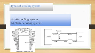
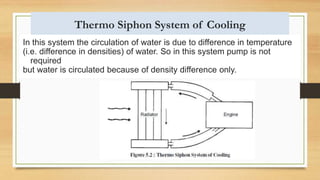
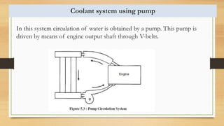
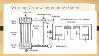
1) Different types of cooling systems like air cooling and water cooling are described. Water cooling further includes thermosiphon and pump circulation systems.
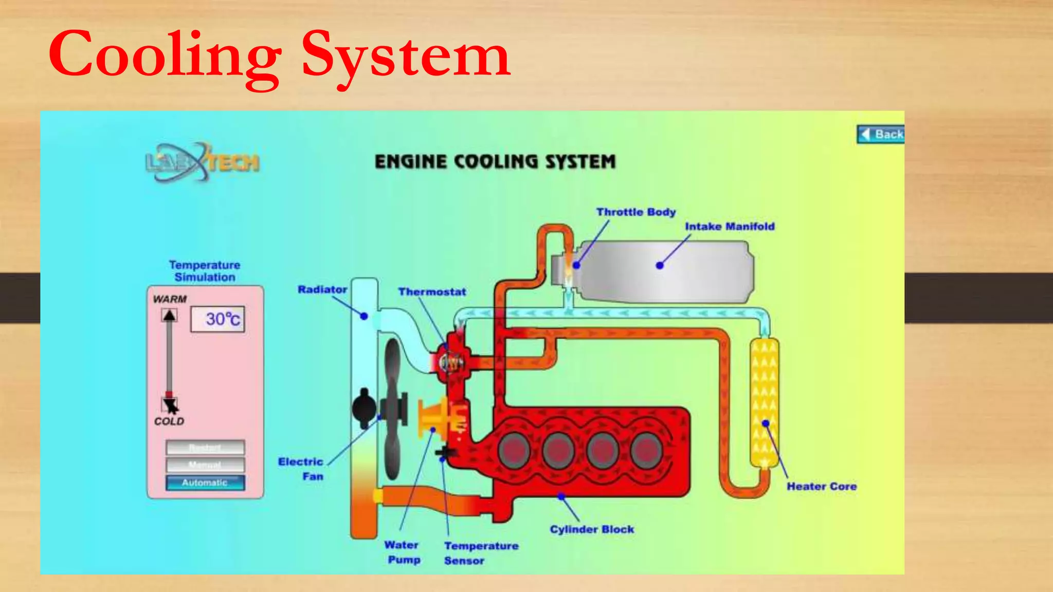
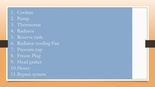
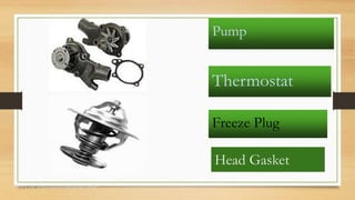
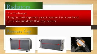
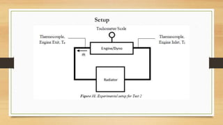
2) Key components of a water cooling system are identified, including the coolant, pump, thermostat, radiator, reserve tank, and fan.
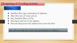
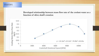
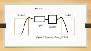
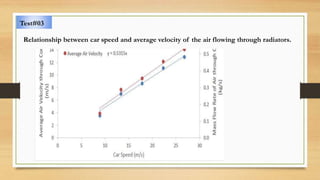
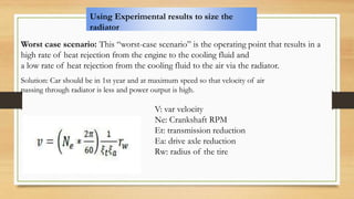
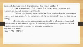
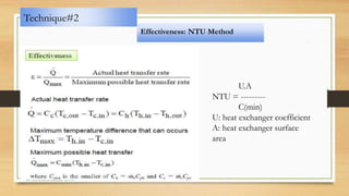
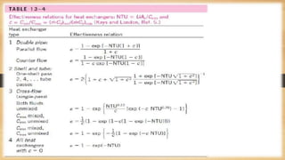
3) Techniques for sizing radiators are outlined, including establishing relationships between various parameters through testing and using effectiveness-NTU or LMTD methods. Worst case scenarios can be used to determine required heat rejection and radiator size.