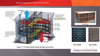
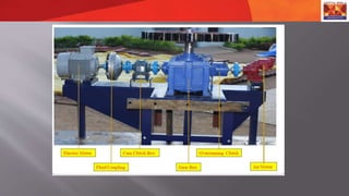
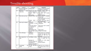
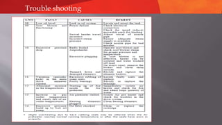
PARAG AGRAWAL
CPP Operation
Certified Energy auditor
Heating Surface m2- 13200/aph
No of APH -2
TYPE:25.5VIT 1900 05.06.2021
 In India, majority of boilers in power industry, are provided with rotary regenerative type
air pre heaters
 These being LUNGS of the boiler, need to be kept in healthy condition to have proper and
efficient ventilation.
REQUIREMENT
 Air pre-heater is an important Boiler auxiliary which primarily preheats the combustion
air for rapid and efficient combustion in the furnace.
 The air heater recovers the waste heat from the outgoing flue gas of a Boiler and transfers
the same to the combustion air.
 In a utility Boiler the flue gas leaves the economizer at a temperature of around 380 deg
C.
 As every 55 deg C drop in flue gas temperature improves the Boiler efficiency by about
2.5%, having an air heater in the downstream of economizer the Boiler efficiency is
considerably improved.
 Further the air heater may also be used for heating the air to dry the coal in the
pulverizing plant.
Advantages of Using Air Heater :
The recovery of waste heat from the flue gas and heating the air required for Boiler In an air heater gives
the following advantages.
1. The Boiler efficiency is increased.
2. More stable combustion in furnace.
3. The combustion is intensified with the use of hot air.
4. Lower grades of coals can be burnt efficiently with hot-air.
5. The use of hot air, improves the heat transfer rate and so less heat transfer area will be required.
6. The combustion is made complete with negligible amount of carbon in ash.
7. Faster load variations are possible.
8. The coal can be dried effectively for easy pulverization and combustion
AIR HEATER TYPES
 There are two main types of air heaters in use; the static recuperative type and the rotary
regenerative type.
 In the recuperative type the flue gas in on one side of the surface and the air is on the other side
The heat from the flue gas is-transferred to the air through the heat transfer surface normally in
form of tubes/ plates.
 In the regenerative type the gas flows through a closely packed matrix or heat transfer element
giving up heat to the air heater elements and so raising the temperature of the matrix. Air is
then pas through and recovers the heat. Either the matrix or the hoaxes may be rotated to
achieve this heat transfer as a continuous process.
Recuperative Type Air Heater
 Tubular air heaters and plate type air heaters are coming under this category. The Plate type heaters are
not generally used in the large capacity Boilers.
ADVANTAGS OF RECUPERATIVE AIR HEATER
 The major advantage is that this type of air heater is not having any moving parts. So the maintenance
involved is less and so no auxiliary power consumption.
 Also there is no possibility of fly ash carry over by the heated air in these air heaters.
DISADVANTAGES OF RECUPERATIVE AIR HEATER
ļ‚” a) As the heat transfer areas are made of tubes or plates the air heater occupies more area. Also it involves more material cost.
ļ‚” b) Any puncture in tubes results in leaking of air into flue gas stream thereby increasing the load on fans.
ļ‚” c) Deposits on the tube surface reduce the heat transfer.
ļ‚” d) Pressure drop of flue gas across the air heater is high.
ļ‚” e) The cross flow heat transfer in tubular air heater is less efficient.
ļ‚” f) Severely affected due to cold end corrosion.
ļ‚” g) Replacement of punctured tubes is a major task requiring more downtime on the boiler.
With the number of disadvantages, the use of recuperative air heaters in large capacity boilers is
becoming unpopular. However in certain boilers, the tubular air heater is used to separately heat the
primary air to avoid carry over of fly ash to pulverize.
Regenerative Air Heater
 In this category there are two types of air heaters. One is the Ljungstrom type with rotating matrix of
heating elements and the other Davidson type with stationary heating elements. The Ljungstrorm air
heaters are mostly used in Indian Power Stations.
LJUNGSTROM AIR HEATER
 Here a matrix is rotated at 2 to 3 rpm and alternatively passes through the gas and air passes. The
heating elements pick up the heat from the flue gas and -the same elements gives the heat to the air
when they move through the air pass. the air heater can be bisector or trisect or. In trisect or air heater,
there will be provision for heating the primary and secondary air streams separately. This facilitates to
handle cold air at the primary air fan.
Construction Details
 The air heater will consist of the following major components.
 Rotor
 Bearing
 Housing
 Connecting Plates
 Sealing arrangement
 Drive Units
 Cleaning Devices
 Safety Devices
Rotary regenerative type air pre heaters
1.2mm thick
1. Rotor Drive Unit :
2. Main Drive : Electric Motor, 7.5 KW, 1500 rpm, Frame
160L,
3. Horizontal Foot Mounted. Refer Note-C.
4. Speed Reducer : Helical Gear Reducer, Ratio 110:1, Two
Input shafts with over running clutch on air motor side.
5. Couplings : Bibby Coupling for Main Drives and Resilient
Coupling for Auxiliary Drive.
6. Auxiliary Drive : Air Motor with Gear Box and Muffler.
Air Motor Inlet connection 1" BSP female.
7. Air Consumption: 5.95 Nm³/min at pressure 6.33
kg/cm²(g).
8. Solenoid Valve : 1" BSP, 240V, De-energised to open.
Note C :
All Electric Motors : Squirrel Cage Induction
type, lP 55 enclosure,
TEFC, 415 V (±10%), 3 Phase, 50 Hz (±5%),
Class 'F' insulation, method of starting Direct
On Line, suitable for an ambient temperature
of 50°C,
conforming to IS:325.
1. Oil Circulation System : Guide Bearing & Support Bearing.
2. Oil Spec : IOC Servocyl C - 680 / equivalent.
3. System : 2 x 100%
4. Screw Pump : 15 LPM
5. Motor : 0.75 KW, 1500 rpm, Frame 90S,
6. Couplings : Lovejoy Coupling L-095.
7. Starting : RTD through DDCMIS if Oil Temp is more than 40°C.
8. Remote Alarm : RTD through DDCMIS if Oil Temp is more than 70°C.
9. Flow Switch : for No - Flow remote alarm.
10. Cooling water : Consumption 1 m³/Hr/system at 5 kg/cm²(g) pr.
11. Connection : 1" BSP female at Oil Cooler Inlet for cooling water. Cooling water piping &
pipe fittings by BHEL, Piping Center.
13.1 FIRE SENSING DEVICE
INTRODUCTION
The primary purpose of this accessory to the Air preheater is to detect small
areas (hot spots ) of hot metal surfaces within the rotating heating element.
TYPES OF HOT SPOT DETECTORS
THERMOCOUPLES:
Even though it is strong enough to withstand the environment, slow in
response to
short duration temperature changes.
ULTRA VIOLET DETECTOR
It requires visible flame for detection and hence not suitable for our purpose
INFRA RED SYSTEM
It is easily adaptable to present day requirements. For our Air preheater we
generally use thermocouple and infrared system only.
REQUIREMENT OF A FIRE DETECTOR
Rapid response time
 Ability to discern metal temperature not more than 150°C above the
maximum Ā· heating element metal temperature under normal operating
conditions.Ā· Ability to detect small fires that are deep within the heating
element pack.Ā· High reliability
·Ease of installation on existing as well as new Air preheaters· Simplicity of
maintenance and servicing.Ā· Ability to provide signal for operating personnel
and ability to monitor the entire rotating structure.
Fire Sensing Thermocouples :
(Supplied in PGMA 52 220 & 52 600)
1. Type : Individual Thermocouples, Chromel - Alumal (K Type, Duplex).
2. Location :
• Five numbers at Cold End Center Section on the Gas Side,
• Five numbers at Hot End Center Section on the Air Side.
3. Remote Alarm : Signal from thermocouple taken to DDCMIS / DCS to generate alarm
incase of abnormal increase in Gas Outlet or Air Outlet Temperatures.
THERMOCOUPLE FIRE DETECTOR - PRINCIPLE OF OPERATION
1. A Thermocouple is a device that converts thermal energy directly into an electric voltage
where a temp gradient exists between the two end junction of a pair of dissimilar metal
wires.
2. This may be applied at any temperature upto 1200 °C for base metals and 1500°C for
noble metals. Base metal couples are made from Chromel-Alumel wire for temperature
upto 1200°C.
3. This system detects a fire situation by sensing an undue temperature rise in the air and
gas flow streams.
4. It consists of a set of thermocouples located strategically in the air preheater flow
streams and a scanner device, which measures, at set intervals, the temperature of each
thermocouple and compares with its set point.
5. In case of a measured value being more than the set point, an alarm contact is closed to
inform the operator about a possible fire situation demanding immediate attention.
1. System: Water Washing and Deluge System :
2. Location : One Wash Pipe in each Gas Inlet & Gas Outlet. One
Deluge Pipe in each Gas Inlet & Gas Outlet.
3. Connection : NB 100 (OD 114.3 mm) Pipe with mating Flanges.
4. Water : Consumption 80 m³/Hr/Pipe at pressure 5
kg/cm²(g).Clean water free from mud & debris shall be used.
During fire fighting, bothWater Washing & Deluge Pipes
shall be opened.
1. Cleaning Device : soot blowers
2. Location : Gas Outlet Duct.
3. Type : Swivel Arm Twin Nozzle.
4. Drive Motor : 0.18 KW, 1500 rpm, Frame 71, Refer Note-C.
5. Speed Reducer : Two Stage Reduction Worm Gear Box, Ratio 4900:1.
6. Cleaning Time : one cycle is approximately 30 minutes.
7. Connection : 1.5" Flanged as per ANSI B16.5 Class 300.
8. Steam : Consumption 2100 kg/hr per device, at pressure 14 kg/cm²(g) & 150°C Superheat. Maximum pressure - 17.6
kg/cm²(g).
9. Air : (required only during oil firing at boiler start up). Service Air Consumption 10.7 Nm³/min/device at pressure 6.33
kg/cm²(g).
Specifications
12.0 CHECKS DURING
OPERATION
12.1 DAILY CHECK
i) Oil levels in
a) Support bearing
b) Guide bearing
c) Main drive gear reducer
d) Air line lubricator
ii) For any unusual noise in
a) Rotor
b) Rotor main drive bearings
c) Drive motor and gear reducer
d) Cleaning device during operation
e) Oil circulation system.
iii) For cleanliness near
a) Rotor drive unit
b) Rotor main bearings
c) Cleaning device
d) Oil circulation system
iv) Instruments for proper working
a) Bearing lube oil thermometers
b) Thermocouples if provided in bearings for alarm or
remote Bearing
lube oil pressure gauges
c) indication.
d) Air inlet and outlet, gas inlet and outlet temperature
measuring
instruments.
e) Manometers for measuring pressure drops across air
preheater for
gas and air flows.
v) The condition of cold end elements through
observation Port by
switching on the inspection lights.
12.3 MONTHLY CHECK
Ā· Check the linkage of power drive cleaning device
(PDCD) from binding.
Ā· Check trunnions are running from rubbing with
packing rings and bearing overs.
Ā· Check gland packing and adjust if necessary.
Ā· Check pinion air seal whether carbon
rings/packing rings are ok.
Ā· Check hot end sector plate and adjuster and hot
end tracking linkages are working properly.
Ā· Check cold end sector plates for looseness, tighten
if necessary.
Check-list
12.2 WEEKLY CHECK
FOR OIL LEAKS
Ā· Around bearing oil drain plugs, instruments
connections etc
Ā· In oil piping
Ā· In threaded connections in oil circulation systems
Attention: Any leak found in the hot end bearing is
to be rectified immediately as this may cause fire
break - out due to high ambient temperature in this
region.
Ā· Around main drive gear reducer drain plugs,
dipstick connections, etc.,Ā· Start and run air motor for
a minute
Ā· Check working of lubrication.
Ā· Give a few turns for the self-cleaning filters if
provided in the circulation system
Ā· Check the operation of solenoid valve
Check-list
2.4 HALF YEARLY CHECK
•Check lubrication of all items and change lubricants as per schedule.
• Examine all the seals of air pre-heaters for wear and tear; if necessary readjust.
•Check the cleanliness of the element baskets; if necessary water wash the heater
•Thoroughly clean the areas around drive units, bearing, oil circulation system,
power driven cleaning device, etc., for dirt, oil etc.Ā· Check the lubrication filter
cartridges for choking and clean / replace the cartridges.
Check-list
12.5 ANNUAL OVERHAUL
1. Ā· Clean up first the entire heater before proceeding with any maintenance work
2. on the Air preheater
3. Ā· Carefully examine the condition of heating element and replace, if necessary.
4. Check cold end gratings for erosion and repair, if necessary.
5. Ā· Repeat half-yearly inspection.
6. Ā· Replace gland packing.
7. Ā· Open inspection cover on bearings and inspect the condition of bearings.
NOTE : WHILE DRAINING THE OLD OIL FROM THE BEARINGS,CAREFULLY EXAMIN FOR ANY
METALLIC FRAGMENTS /
CONTAMINATION.
1. a) Examine trunnion bolts.
2. b) Examine rotor post to diaphragm welds at the trunnion ends.
3. c) Open pinion cover. Examine pinion and pin rack for wear and tear and proper
4. engagement.
5. d) Pack all electric motor bearing with fresh grease. ( Refer manufacturer's
6. instruction in O&M manual)
7. e) Change gear reducer oil and inspect the old oil for metal fragments.
8. f) Open inspection covers to examine the condition of gears, pinions and
9. bearings.
10. g) Lubricate all couplings grid / gear type.
ANNUAL OVERHAUL
Change oil in the fluid coupling
i) Change the oil seals in the oil pump, if necessary.
j) Check the calibration of all instruments.
k) Examine oil line for dents, cracks, damages, etc.
l) Cleaning device gear boxes to be examined.
m) Steam blowing nozzles to be checked
s) Water washing nozzles to be inspected and cleaned, if necessary.
t) Carefully examine for corrosion at the cold end. If corrosion has
damaged the cold end, the basket can be reversed and installed
u) Examine tube braces for erosion.
v) Check all static seals for erosion replace or repair if necessary.
w) Examine hot end sector plate in-board support plate and adjuster links
For erosion – repair if necessary.
x) Inspect all adjuster mechanisms of sector plates and axial seal plates
for correct positioning and locking.
y) Check axial seal plate to sector plate seals for erosion and replace if
Necessary.
z) Check oil carry over detector for any erosion, if necessary rework it.
Most common problems associated with these air pre heaters are
1. Seal leakages.
2. Erosion of heating elements on HOT end side.
3. Choking up of heating elements at inboard side of HOT end & COLD
end sides
All of these result in poor thermal performance of APH’s, loss in boiler Efficiency, and reduction in
generation due to lost margins of I.D. fans.
Case Studies
Case
Study
Case
Study
SAFETY DEVICES
 ROTOR STOPPAGE ALARM
ļ‚” By any means, if the rotor stops or slows down, there comes to the rescue of the air preheater a rotor stoppage alarm. Equally
spaced proximity switch, which in turn twin strider the timers, inside the rotor stoppage alarm, and timing out of any of these
times will give both audio and visual alarm.
 FIRE SENSING DEVICE
There are two types of fire sensing device; one is the thermocouple type and the other is the infra red detecting system.
ļ‚” THERMOCOUPLE TYPE
 A number of thermocouple Junctions are exposed to air and gas stream, and their outputs are continuously compared with the
preset value. If any variations are noticed triggering of alarm will take place to indicate the probabilities of fire.
ļ‚” INFRA RED DETECTION SYSTEM
 This infrared detecting system works on the principle that by finding the level of the infrared radiation emitted by the hot
sources. The firing potential could be ascertained. These sophisticated systems right now are imported and are quite expensive.
For our type of operations it is felt that the thermocouple type itself is sufficient.
 FIRE FIGHTING EQUIPMENT
ļ‚” If at all fire takes place then the deluge system provided in the air preheater will come to the rescue. Through the number of
nozzles provided in the manifolds high volume, medium pressure water can be flooded. Among the various alternatives this
arrangement seems to be the best from the experience of air preheater field engineers. Only thing water in sufficient quantity
should be made to flood the firing zone.
1. Air preheater fires are rare. A fire may occur during cold start up on oil or start-up
following hot stand-by because of poor combustion of the oil fuel.
2. The improper combustion results in unburnt or partially burnt oil condensing and
depositing on the air preheater element surface. As the temperature entering the air
preheater increases, this deposit is baked to a hard varnish-like material. These deposits
can ignite as temperature increases to 315-370 °C range.
3. This ignition usually starts in a small area of the deposit. During the early stages of
deposit generated is carried away from the area of its origin. Downstream mixing of the
fluids further minimises any external effect.
4. Most of the heat generated is absorbed by the metal heat transfer element nearby. The
actual temperature build up during this period is relatively slow. If the condition can be
detected at that time, the amount of water required to reduce the temperatures quickly
to below the ignition temperature, is much less.If this ignited deposit remains
undetected it will continue to generate heat until the metal heat transfer element reaches
730 to 765 °C. At this point, metal may ignite with temperatures reaching 1650 °C and
higher in a matter of minutes.
5. Metal fires are self-sustaining and would require more water than is normally available
to drop the temperature to a reasonable level. It should be noted that CO2, Halon and
other extinguishing agents are ineffective under these circumstances.
TROUBLE
SHOOTING
Trouble shooting
Trouble shooting
 Fouling
 Plugging
 Corrosion
 Cleaning of APH
 Erosion
 fire
 Deposits in air heater are initiated by condensation of acid an
moisture from flue gas on metal surface operating at
temperature at below due point .Other things remaining same,
degree of fouling depends on air heater heating element metal
surface. Minimum metal temperature occurs at the cold end
,where as a result, most fouling and corrosion occur.
 In case of oil firing, the corrosion and plugging due to corrosive
products of combustion are very common ,the gas outlet
temperature or air inlet temperature has to be raised to restrict to
corrosion to the permissible level.
 air inlet temperature is increased mostly by steam air heating to maintain
the recommended cold end average temperature for the installation.
 corrosion resistance alloys like corben steel can be used for cold end.
 easily and economically replaceable cold end portion of airheater without
much outage period.
 design the boiler for high flue gas exit temperature which means lesser
efficiency of boiler.
 effective on load blowing of air heaters with superheated steam accelerates
fouling and corrosion.
1.ON-LOAD CLEANING
a) Recuperative type
Proven practical method is by soot cleaning.
b) Regenerative type
Fixed or moving type soot blowers with multinozzle thoroughly cleans the
airpreheater.
a) Recuperative type
If not provide with on-load cleaning at intervals during shutdown by hand or mechanical
method. large quantity of cold or warm water can also be used for this purpose. small
quantity of water is actually do harm by making deposited by compact and hard.
b) Regenerative type
Normally on-load cleaning devices keep them clean and if it is needed to clean during shut-
down large quantities of water may be used. it deposited is severe, sometimes soda-ash
solution may assist in dissolving it. water requirement for cleaning is less when compared
to static type.
 1.use of low sulphur oil during the above condition.
 2.by-pass cold air so that gas temperature can be kept at a higher
level.
 3.by-pass of gas so that acid condensation on airheater does not
occur at all.
 4.increase the air inlet temperature having steam coil air
preheaters
 5.recirculate the hot air.
 Observed pressure drop across the APH for measure degree of
fouling.
 APH soot blowing done on regular basis.
 Measured all parameters on regular basis.
 Inspection of all duct and seals for leakage.
APH
performance
 Ash hopper seals
 Ash hopper door left open
 Defective expansion joints
 Duct openings uncovered
 Boiler roof seals defective
 Attemperating air dampers passing
 A.H.Air bypassing dampers passing
 Suction milling plant
 Worn shaft seal on exhausters
 Gas outlet temperature
lower than optimum
ļ‚” Leads to cold end corrosion
 Loss of heat transfer elements
 Gas outlet temperature higher
than optimum
ļ‚” More dry gas loss
ļ‚” Rise of 220c above optimum reduce
boiler efficiency by 1%
ļ‚” 20C RISE ABOVE OPTIMUM
RESULTS LOSS OF 600kcal HEAT
IN 1 TONNE OF F.G.
 LOWER THAN OPTIMUM
ļ‚” LIGHTING AND FIRING
COLD BOILER
 USE SCAPH
ļ‚” AIR LEAKAGE
 SEALS CONDITON
 DIFF. PR. BETWEEN AIR AND
F.G
 HIGHER THAN OPTIMUM
ļ‚” QTY. OF AIR PASSING THROUGH A.H.
 TEMPERING AIR
 SETTING INFILTRATION
 BYPASS DAMPERS PASSING
ļ‚” TEMP.OF GAS ENTERING A.H
 DEPOSITS ON BOILER HEAT TRANSFER AREAS
 DELAYED/SY.COMBUSTION
 FEED WATER TEMP
ļ‚” FOULED / CORRODED ELEMENTS
ļ‚” DEFECTIVE BAFFLES
ļ‚” QTY.OFGAS PASSING THROUGH A.H.
 Effects of leakage :
 Air leakage has the largest single drawback on APH performance.
 Increased auxiliary power consumption, and higher-pressure differentials that can limit
combustion air fan operation.
 Air heater leakage % can be determined using this procedure, which is defined as the
weight of air passing from the airside to the gas side of the air heater.
 This index is an indicator of the condition of the air heater’s seals. As air heater seals wear,
air heater leakage increases.
 The increase in air heater leakage increases the station service power requirements of the
forced draft and induced draft fans, increasing unit net heat rate and at times limiting unit
capacity.
 There are many factors depend on air preheater performance like as high seal
leakage, basket element fouling and plugging.
Principle of operation: Air preheater test is conducted of regenerative type air
preheater to improve efficiency. Various performance like as air preheater
leakage, air and gas side efficiency, X-ratio are determine using test.
A decrease in air leakage area, increase in air and gas side efficiency and X-
ratio indicates maximum heat recovery in the Air preheater.
Test set up: Instrument required are gas analyser, digital thermometer.
Test procedure is during full load condition and same mills running. The
operation of test run is as follows.
 a. No Air heater soot blowing is done during the test.
 b. Unit operation is kept steady at least 60 minutes prior to the test.
 c. No mill changeover.
APH performance monitoring
Thanks
Pls give your feedback and suggestion
Parag agrawal
Mob 8102392375
Mail Id :agrawalparag2001@gmail.com

Aph operation and emergency handling

  • 1.
    PARAG AGRAWAL CPP Operation CertifiedEnergy auditor Heating Surface m2- 13200/aph No of APH -2 TYPE:25.5VIT 1900 05.06.2021
  • 2.
     In India,majority of boilers in power industry, are provided with rotary regenerative type air pre heaters  These being LUNGS of the boiler, need to be kept in healthy condition to have proper and efficient ventilation. REQUIREMENT  Air pre-heater is an important Boiler auxiliary which primarily preheats the combustion air for rapid and efficient combustion in the furnace.  The air heater recovers the waste heat from the outgoing flue gas of a Boiler and transfers the same to the combustion air.  In a utility Boiler the flue gas leaves the economizer at a temperature of around 380 deg C.  As every 55 deg C drop in flue gas temperature improves the Boiler efficiency by about 2.5%, having an air heater in the downstream of economizer the Boiler efficiency is considerably improved.  Further the air heater may also be used for heating the air to dry the coal in the pulverizing plant.
  • 3.
    Advantages of UsingAir Heater : The recovery of waste heat from the flue gas and heating the air required for Boiler In an air heater gives the following advantages. 1. The Boiler efficiency is increased. 2. More stable combustion in furnace. 3. The combustion is intensified with the use of hot air. 4. Lower grades of coals can be burnt efficiently with hot-air. 5. The use of hot air, improves the heat transfer rate and so less heat transfer area will be required. 6. The combustion is made complete with negligible amount of carbon in ash. 7. Faster load variations are possible. 8. The coal can be dried effectively for easy pulverization and combustion
  • 4.
    AIR HEATER TYPES There are two main types of air heaters in use; the static recuperative type and the rotary regenerative type.  In the recuperative type the flue gas in on one side of the surface and the air is on the other side The heat from the flue gas is-transferred to the air through the heat transfer surface normally in form of tubes/ plates.  In the regenerative type the gas flows through a closely packed matrix or heat transfer element giving up heat to the air heater elements and so raising the temperature of the matrix. Air is then pas through and recovers the heat. Either the matrix or the hoaxes may be rotated to achieve this heat transfer as a continuous process.
  • 5.
    Recuperative Type AirHeater  Tubular air heaters and plate type air heaters are coming under this category. The Plate type heaters are not generally used in the large capacity Boilers. ADVANTAGS OF RECUPERATIVE AIR HEATER  The major advantage is that this type of air heater is not having any moving parts. So the maintenance involved is less and so no auxiliary power consumption.  Also there is no possibility of fly ash carry over by the heated air in these air heaters. DISADVANTAGES OF RECUPERATIVE AIR HEATER ļ‚” a) As the heat transfer areas are made of tubes or plates the air heater occupies more area. Also it involves more material cost. ļ‚” b) Any puncture in tubes results in leaking of air into flue gas stream thereby increasing the load on fans. ļ‚” c) Deposits on the tube surface reduce the heat transfer. ļ‚” d) Pressure drop of flue gas across the air heater is high. ļ‚” e) The cross flow heat transfer in tubular air heater is less efficient. ļ‚” f) Severely affected due to cold end corrosion. ļ‚” g) Replacement of punctured tubes is a major task requiring more downtime on the boiler. With the number of disadvantages, the use of recuperative air heaters in large capacity boilers is becoming unpopular. However in certain boilers, the tubular air heater is used to separately heat the primary air to avoid carry over of fly ash to pulverize.
  • 6.
    Regenerative Air Heater In this category there are two types of air heaters. One is the Ljungstrom type with rotating matrix of heating elements and the other Davidson type with stationary heating elements. The Ljungstrorm air heaters are mostly used in Indian Power Stations. LJUNGSTROM AIR HEATER  Here a matrix is rotated at 2 to 3 rpm and alternatively passes through the gas and air passes. The heating elements pick up the heat from the flue gas and -the same elements gives the heat to the air when they move through the air pass. the air heater can be bisector or trisect or. In trisect or air heater, there will be provision for heating the primary and secondary air streams separately. This facilitates to handle cold air at the primary air fan.
  • 7.
    Construction Details  Theair heater will consist of the following major components.  Rotor  Bearing  Housing  Connecting Plates  Sealing arrangement  Drive Units  Cleaning Devices  Safety Devices
  • 8.
    Rotary regenerative typeair pre heaters 1.2mm thick
  • 10.
    1. Rotor DriveUnit : 2. Main Drive : Electric Motor, 7.5 KW, 1500 rpm, Frame 160L, 3. Horizontal Foot Mounted. Refer Note-C. 4. Speed Reducer : Helical Gear Reducer, Ratio 110:1, Two Input shafts with over running clutch on air motor side. 5. Couplings : Bibby Coupling for Main Drives and Resilient Coupling for Auxiliary Drive. 6. Auxiliary Drive : Air Motor with Gear Box and Muffler. Air Motor Inlet connection 1" BSP female. 7. Air Consumption: 5.95 Nm³/min at pressure 6.33 kg/cm²(g). 8. Solenoid Valve : 1" BSP, 240V, De-energised to open. Note C : All Electric Motors : Squirrel Cage Induction type, lP 55 enclosure, TEFC, 415 V (±10%), 3 Phase, 50 Hz (±5%), Class 'F' insulation, method of starting Direct On Line, suitable for an ambient temperature of 50°C, conforming to IS:325.
  • 11.
    1. Oil CirculationSystem : Guide Bearing & Support Bearing. 2. Oil Spec : IOC Servocyl C - 680 / equivalent. 3. System : 2 x 100% 4. Screw Pump : 15 LPM 5. Motor : 0.75 KW, 1500 rpm, Frame 90S, 6. Couplings : Lovejoy Coupling L-095. 7. Starting : RTD through DDCMIS if Oil Temp is more than 40°C. 8. Remote Alarm : RTD through DDCMIS if Oil Temp is more than 70°C. 9. Flow Switch : for No - Flow remote alarm. 10. Cooling water : Consumption 1 m³/Hr/system at 5 kg/cm²(g) pr. 11. Connection : 1" BSP female at Oil Cooler Inlet for cooling water. Cooling water piping & pipe fittings by BHEL, Piping Center.
  • 12.
    13.1 FIRE SENSINGDEVICE INTRODUCTION The primary purpose of this accessory to the Air preheater is to detect small areas (hot spots ) of hot metal surfaces within the rotating heating element. TYPES OF HOT SPOT DETECTORS THERMOCOUPLES: Even though it is strong enough to withstand the environment, slow in response to short duration temperature changes. ULTRA VIOLET DETECTOR It requires visible flame for detection and hence not suitable for our purpose INFRA RED SYSTEM It is easily adaptable to present day requirements. For our Air preheater we generally use thermocouple and infrared system only.
  • 13.
    REQUIREMENT OF AFIRE DETECTOR Rapid response time  Ability to discern metal temperature not more than 150°C above the maximum · heating element metal temperature under normal operating conditions.· Ability to detect small fires that are deep within the heating element pack.· High reliability ·Ease of installation on existing as well as new Air preheaters· Simplicity of maintenance and servicing.· Ability to provide signal for operating personnel and ability to monitor the entire rotating structure.
  • 14.
    Fire Sensing Thermocouples: (Supplied in PGMA 52 220 & 52 600) 1. Type : Individual Thermocouples, Chromel - Alumal (K Type, Duplex). 2. Location : • Five numbers at Cold End Center Section on the Gas Side, • Five numbers at Hot End Center Section on the Air Side. 3. Remote Alarm : Signal from thermocouple taken to DDCMIS / DCS to generate alarm incase of abnormal increase in Gas Outlet or Air Outlet Temperatures.
  • 15.
    THERMOCOUPLE FIRE DETECTOR- PRINCIPLE OF OPERATION 1. A Thermocouple is a device that converts thermal energy directly into an electric voltage where a temp gradient exists between the two end junction of a pair of dissimilar metal wires. 2. This may be applied at any temperature upto 1200 °C for base metals and 1500°C for noble metals. Base metal couples are made from Chromel-Alumel wire for temperature upto 1200°C. 3. This system detects a fire situation by sensing an undue temperature rise in the air and gas flow streams. 4. It consists of a set of thermocouples located strategically in the air preheater flow streams and a scanner device, which measures, at set intervals, the temperature of each thermocouple and compares with its set point. 5. In case of a measured value being more than the set point, an alarm contact is closed to inform the operator about a possible fire situation demanding immediate attention.
  • 16.
    1. System: WaterWashing and Deluge System : 2. Location : One Wash Pipe in each Gas Inlet & Gas Outlet. One Deluge Pipe in each Gas Inlet & Gas Outlet. 3. Connection : NB 100 (OD 114.3 mm) Pipe with mating Flanges. 4. Water : Consumption 80 m³/Hr/Pipe at pressure 5 kg/cm²(g).Clean water free from mud & debris shall be used. During fire fighting, bothWater Washing & Deluge Pipes shall be opened.
  • 17.
    1. Cleaning Device: soot blowers 2. Location : Gas Outlet Duct. 3. Type : Swivel Arm Twin Nozzle. 4. Drive Motor : 0.18 KW, 1500 rpm, Frame 71, Refer Note-C. 5. Speed Reducer : Two Stage Reduction Worm Gear Box, Ratio 4900:1. 6. Cleaning Time : one cycle is approximately 30 minutes. 7. Connection : 1.5" Flanged as per ANSI B16.5 Class 300. 8. Steam : Consumption 2100 kg/hr per device, at pressure 14 kg/cm²(g) & 150°C Superheat. Maximum pressure - 17.6 kg/cm²(g). 9. Air : (required only during oil firing at boiler start up). Service Air Consumption 10.7 Nm³/min/device at pressure 6.33 kg/cm²(g).
  • 18.
    Specifications 12.0 CHECKS DURING OPERATION 12.1DAILY CHECK i) Oil levels in a) Support bearing b) Guide bearing c) Main drive gear reducer d) Air line lubricator ii) For any unusual noise in a) Rotor b) Rotor main drive bearings c) Drive motor and gear reducer d) Cleaning device during operation e) Oil circulation system. iii) For cleanliness near a) Rotor drive unit b) Rotor main bearings c) Cleaning device d) Oil circulation system iv) Instruments for proper working a) Bearing lube oil thermometers b) Thermocouples if provided in bearings for alarm or remote Bearing lube oil pressure gauges c) indication. d) Air inlet and outlet, gas inlet and outlet temperature measuring instruments. e) Manometers for measuring pressure drops across air preheater for gas and air flows. v) The condition of cold end elements through observation Port by switching on the inspection lights.
  • 19.
    12.3 MONTHLY CHECK Ā·Check the linkage of power drive cleaning device (PDCD) from binding. Ā· Check trunnions are running from rubbing with packing rings and bearing overs. Ā· Check gland packing and adjust if necessary. Ā· Check pinion air seal whether carbon rings/packing rings are ok. Ā· Check hot end sector plate and adjuster and hot end tracking linkages are working properly. Ā· Check cold end sector plates for looseness, tighten if necessary. Check-list 12.2 WEEKLY CHECK FOR OIL LEAKS Ā· Around bearing oil drain plugs, instruments connections etc Ā· In oil piping Ā· In threaded connections in oil circulation systems Attention: Any leak found in the hot end bearing is to be rectified immediately as this may cause fire break - out due to high ambient temperature in this region. Ā· Around main drive gear reducer drain plugs, dipstick connections, etc.,Ā· Start and run air motor for a minute Ā· Check working of lubrication. Ā· Give a few turns for the self-cleaning filters if provided in the circulation system Ā· Check the operation of solenoid valve
  • 20.
    Check-list 2.4 HALF YEARLYCHECK •Check lubrication of all items and change lubricants as per schedule. • Examine all the seals of air pre-heaters for wear and tear; if necessary readjust. •Check the cleanliness of the element baskets; if necessary water wash the heater •Thoroughly clean the areas around drive units, bearing, oil circulation system, power driven cleaning device, etc., for dirt, oil etc.Ā· Check the lubrication filter cartridges for choking and clean / replace the cartridges.
  • 21.
    Check-list 12.5 ANNUAL OVERHAUL 1.Ā· Clean up first the entire heater before proceeding with any maintenance work 2. on the Air preheater 3. Ā· Carefully examine the condition of heating element and replace, if necessary. 4. Check cold end gratings for erosion and repair, if necessary. 5. Ā· Repeat half-yearly inspection. 6. Ā· Replace gland packing. 7. Ā· Open inspection cover on bearings and inspect the condition of bearings. NOTE : WHILE DRAINING THE OLD OIL FROM THE BEARINGS,CAREFULLY EXAMIN FOR ANY METALLIC FRAGMENTS / CONTAMINATION. 1. a) Examine trunnion bolts. 2. b) Examine rotor post to diaphragm welds at the trunnion ends. 3. c) Open pinion cover. Examine pinion and pin rack for wear and tear and proper 4. engagement. 5. d) Pack all electric motor bearing with fresh grease. ( Refer manufacturer's 6. instruction in O&M manual) 7. e) Change gear reducer oil and inspect the old oil for metal fragments. 8. f) Open inspection covers to examine the condition of gears, pinions and 9. bearings. 10. g) Lubricate all couplings grid / gear type.
  • 22.
    ANNUAL OVERHAUL Change oilin the fluid coupling i) Change the oil seals in the oil pump, if necessary. j) Check the calibration of all instruments. k) Examine oil line for dents, cracks, damages, etc. l) Cleaning device gear boxes to be examined. m) Steam blowing nozzles to be checked s) Water washing nozzles to be inspected and cleaned, if necessary. t) Carefully examine for corrosion at the cold end. If corrosion has damaged the cold end, the basket can be reversed and installed u) Examine tube braces for erosion. v) Check all static seals for erosion replace or repair if necessary. w) Examine hot end sector plate in-board support plate and adjuster links For erosion – repair if necessary. x) Inspect all adjuster mechanisms of sector plates and axial seal plates for correct positioning and locking. y) Check axial seal plate to sector plate seals for erosion and replace if Necessary. z) Check oil carry over detector for any erosion, if necessary rework it.
  • 23.
    Most common problemsassociated with these air pre heaters are 1. Seal leakages. 2. Erosion of heating elements on HOT end side. 3. Choking up of heating elements at inboard side of HOT end & COLD end sides All of these result in poor thermal performance of APH’s, loss in boiler Efficiency, and reduction in generation due to lost margins of I.D. fans.
  • 24.
  • 25.
  • 26.
  • 27.
    SAFETY DEVICES  ROTORSTOPPAGE ALARM ļ‚” By any means, if the rotor stops or slows down, there comes to the rescue of the air preheater a rotor stoppage alarm. Equally spaced proximity switch, which in turn twin strider the timers, inside the rotor stoppage alarm, and timing out of any of these times will give both audio and visual alarm.  FIRE SENSING DEVICE There are two types of fire sensing device; one is the thermocouple type and the other is the infra red detecting system. ļ‚” THERMOCOUPLE TYPE  A number of thermocouple Junctions are exposed to air and gas stream, and their outputs are continuously compared with the preset value. If any variations are noticed triggering of alarm will take place to indicate the probabilities of fire. ļ‚” INFRA RED DETECTION SYSTEM  This infrared detecting system works on the principle that by finding the level of the infrared radiation emitted by the hot sources. The firing potential could be ascertained. These sophisticated systems right now are imported and are quite expensive. For our type of operations it is felt that the thermocouple type itself is sufficient.  FIRE FIGHTING EQUIPMENT ļ‚” If at all fire takes place then the deluge system provided in the air preheater will come to the rescue. Through the number of nozzles provided in the manifolds high volume, medium pressure water can be flooded. Among the various alternatives this arrangement seems to be the best from the experience of air preheater field engineers. Only thing water in sufficient quantity should be made to flood the firing zone.
  • 29.
    1. Air preheaterfires are rare. A fire may occur during cold start up on oil or start-up following hot stand-by because of poor combustion of the oil fuel. 2. The improper combustion results in unburnt or partially burnt oil condensing and depositing on the air preheater element surface. As the temperature entering the air preheater increases, this deposit is baked to a hard varnish-like material. These deposits can ignite as temperature increases to 315-370 °C range. 3. This ignition usually starts in a small area of the deposit. During the early stages of deposit generated is carried away from the area of its origin. Downstream mixing of the fluids further minimises any external effect. 4. Most of the heat generated is absorbed by the metal heat transfer element nearby. The actual temperature build up during this period is relatively slow. If the condition can be detected at that time, the amount of water required to reduce the temperatures quickly to below the ignition temperature, is much less.If this ignited deposit remains undetected it will continue to generate heat until the metal heat transfer element reaches 730 to 765 °C. At this point, metal may ignite with temperatures reaching 1650 °C and higher in a matter of minutes. 5. Metal fires are self-sustaining and would require more water than is normally available to drop the temperature to a reasonable level. It should be noted that CO2, Halon and other extinguishing agents are ineffective under these circumstances.
  • 30.
  • 31.
  • 32.
  • 33.
     Fouling  Plugging Corrosion  Cleaning of APH  Erosion  fire
  • 34.
     Deposits inair heater are initiated by condensation of acid an moisture from flue gas on metal surface operating at temperature at below due point .Other things remaining same, degree of fouling depends on air heater heating element metal surface. Minimum metal temperature occurs at the cold end ,where as a result, most fouling and corrosion occur.
  • 35.
     In caseof oil firing, the corrosion and plugging due to corrosive products of combustion are very common ,the gas outlet temperature or air inlet temperature has to be raised to restrict to corrosion to the permissible level.
  • 36.
     air inlettemperature is increased mostly by steam air heating to maintain the recommended cold end average temperature for the installation.  corrosion resistance alloys like corben steel can be used for cold end.  easily and economically replaceable cold end portion of airheater without much outage period.  design the boiler for high flue gas exit temperature which means lesser efficiency of boiler.  effective on load blowing of air heaters with superheated steam accelerates fouling and corrosion.
  • 37.
    1.ON-LOAD CLEANING a) Recuperativetype Proven practical method is by soot cleaning. b) Regenerative type Fixed or moving type soot blowers with multinozzle thoroughly cleans the airpreheater.
  • 38.
    a) Recuperative type Ifnot provide with on-load cleaning at intervals during shutdown by hand or mechanical method. large quantity of cold or warm water can also be used for this purpose. small quantity of water is actually do harm by making deposited by compact and hard. b) Regenerative type Normally on-load cleaning devices keep them clean and if it is needed to clean during shut- down large quantities of water may be used. it deposited is severe, sometimes soda-ash solution may assist in dissolving it. water requirement for cleaning is less when compared to static type.
  • 39.
     1.use oflow sulphur oil during the above condition.  2.by-pass cold air so that gas temperature can be kept at a higher level.  3.by-pass of gas so that acid condensation on airheater does not occur at all.  4.increase the air inlet temperature having steam coil air preheaters  5.recirculate the hot air.
  • 40.
     Observed pressuredrop across the APH for measure degree of fouling.  APH soot blowing done on regular basis.  Measured all parameters on regular basis.  Inspection of all duct and seals for leakage.
  • 41.
  • 42.
     Ash hopperseals  Ash hopper door left open  Defective expansion joints  Duct openings uncovered  Boiler roof seals defective  Attemperating air dampers passing  A.H.Air bypassing dampers passing  Suction milling plant  Worn shaft seal on exhausters
  • 43.
     Gas outlettemperature lower than optimum ļ‚” Leads to cold end corrosion  Loss of heat transfer elements  Gas outlet temperature higher than optimum ļ‚” More dry gas loss ļ‚” Rise of 220c above optimum reduce boiler efficiency by 1% ļ‚” 20C RISE ABOVE OPTIMUM RESULTS LOSS OF 600kcal HEAT IN 1 TONNE OF F.G.
  • 44.
     LOWER THANOPTIMUM ļ‚” LIGHTING AND FIRING COLD BOILER  USE SCAPH ļ‚” AIR LEAKAGE  SEALS CONDITON  DIFF. PR. BETWEEN AIR AND F.G  HIGHER THAN OPTIMUM ļ‚” QTY. OF AIR PASSING THROUGH A.H.  TEMPERING AIR  SETTING INFILTRATION  BYPASS DAMPERS PASSING ļ‚” TEMP.OF GAS ENTERING A.H  DEPOSITS ON BOILER HEAT TRANSFER AREAS  DELAYED/SY.COMBUSTION  FEED WATER TEMP ļ‚” FOULED / CORRODED ELEMENTS ļ‚” DEFECTIVE BAFFLES ļ‚” QTY.OFGAS PASSING THROUGH A.H.
  • 45.
     Effects ofleakage :  Air leakage has the largest single drawback on APH performance.  Increased auxiliary power consumption, and higher-pressure differentials that can limit combustion air fan operation.  Air heater leakage % can be determined using this procedure, which is defined as the weight of air passing from the airside to the gas side of the air heater.  This index is an indicator of the condition of the air heater’s seals. As air heater seals wear, air heater leakage increases.  The increase in air heater leakage increases the station service power requirements of the forced draft and induced draft fans, increasing unit net heat rate and at times limiting unit capacity.
  • 46.
     There aremany factors depend on air preheater performance like as high seal leakage, basket element fouling and plugging. Principle of operation: Air preheater test is conducted of regenerative type air preheater to improve efficiency. Various performance like as air preheater leakage, air and gas side efficiency, X-ratio are determine using test. A decrease in air leakage area, increase in air and gas side efficiency and X- ratio indicates maximum heat recovery in the Air preheater. Test set up: Instrument required are gas analyser, digital thermometer. Test procedure is during full load condition and same mills running. The operation of test run is as follows.  a. No Air heater soot blowing is done during the test.  b. Unit operation is kept steady at least 60 minutes prior to the test.  c. No mill changeover. APH performance monitoring
  • 47.
    Thanks Pls give yourfeedback and suggestion Parag agrawal Mob 8102392375 Mail Id :agrawalparag2001@gmail.com