Downloaded 143 times
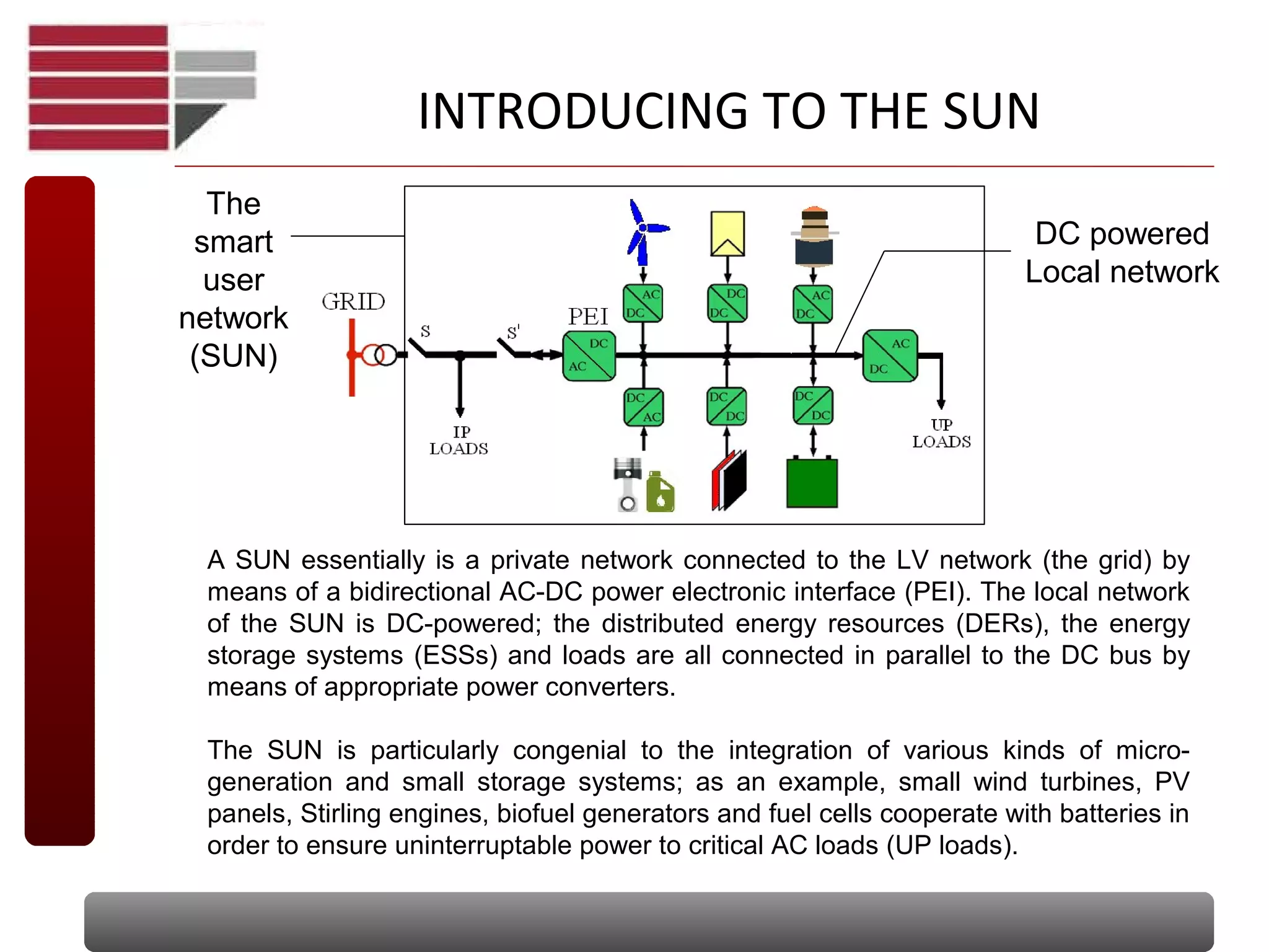
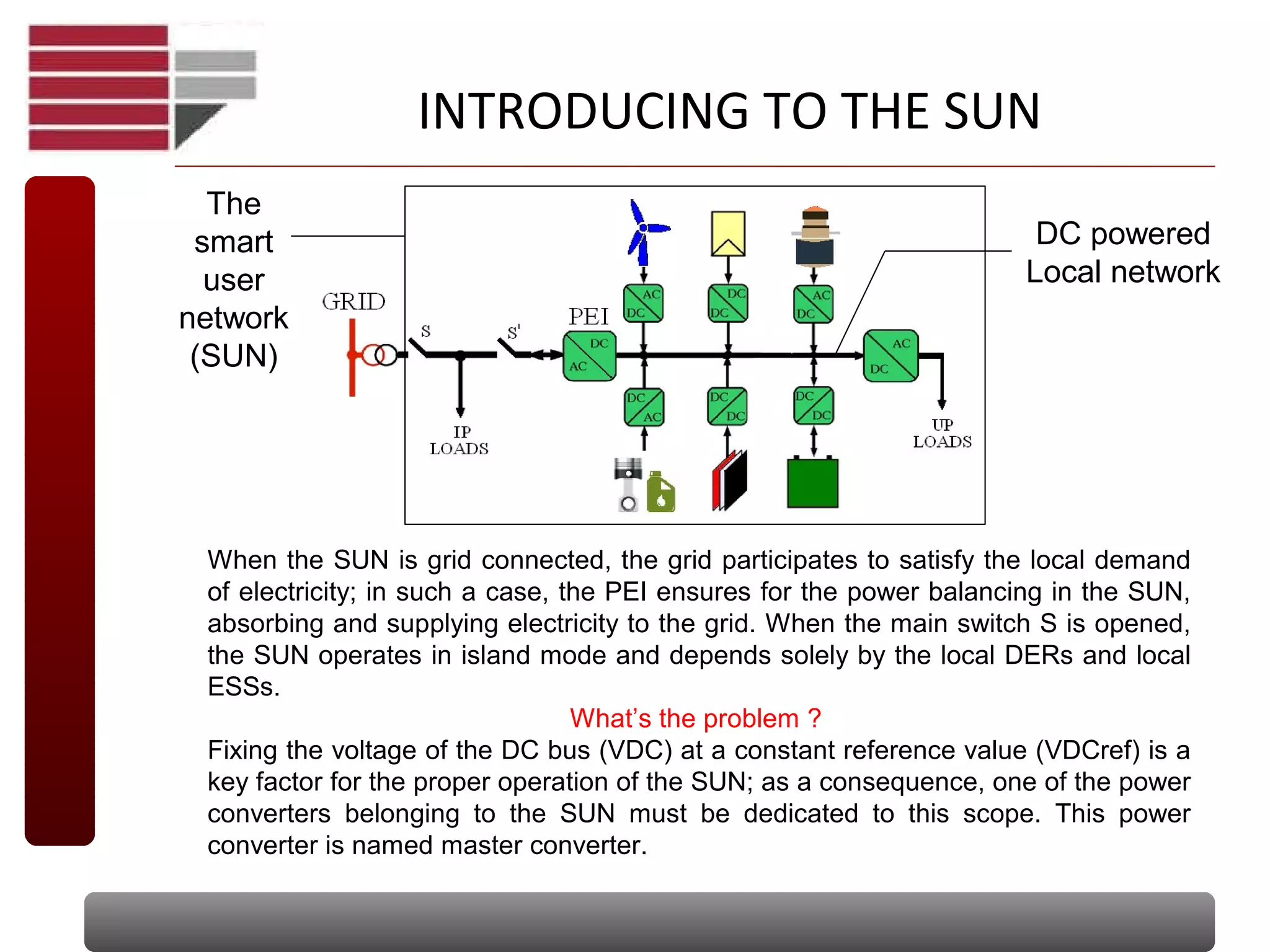


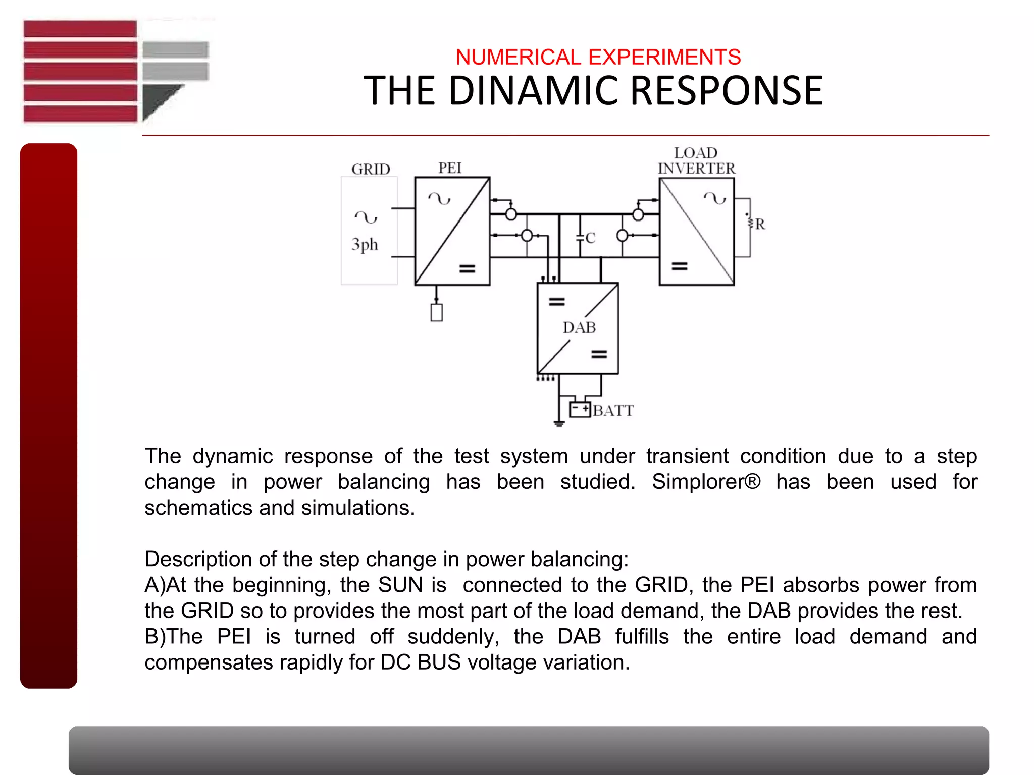


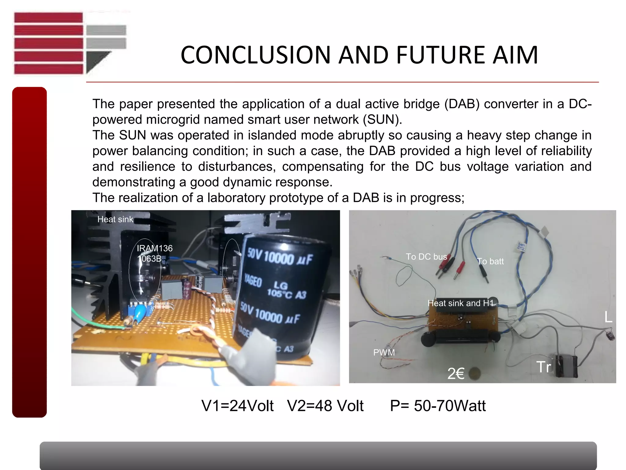

The document discusses a dual active bridge (DAB) DC-DC converter utilized in a smart user network (SUN) powered by direct current, designed to manage power distribution and voltage stability. It highlights the roles of the power electronic interface (PEI) and master converter in grid-connected and island modes, showcasing the DAB's ability to maintain consistent voltage during load variations. The findings indicate the DAB converter's effectiveness in enhancing reliability and dynamic response within a microgrid, with ongoing efforts to develop a laboratory prototype.