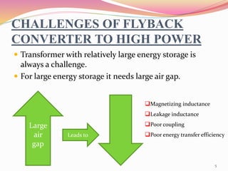
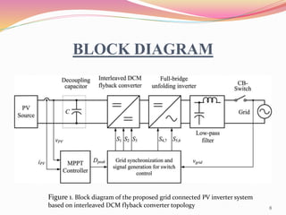
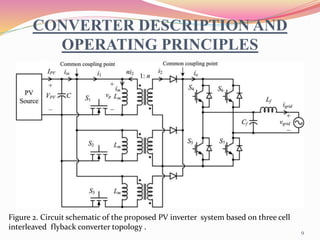
SlideShare a Scribd company logo
Guided by ; Presented by
Mrs. DEEPA M U Ajmal khan N
Asst. Pro., EEE Dept. Roll. No: 03
EEE, S7
1
CONTENTS
 INTRODUCTION
 FLYBACK CONVERTER
 CHALLENGES OF FLYBACK CONVERTER
 DISCONTINUOUS CURRENT MODE
 BLOCK DIAGRAM
 CONVERTER DESCRIPTION AND OPERATING PRINCIPLE
 CONVERTER ANALYSIS
 FLYBACK TRANSFORMER DESIGN
 CONTROL SYSTEM DESIGN
 SIMULATION RESULTS
 EXPERIMENTAL RESULTS
 CONCLUSION
 REFERENCES
2
INTRODUCTION
 Electricity is the most versatile and widely used form of
energy.
 It’s global demand is increasing.
 The solar energy is considered as the most renewable
and freely available source of energy.
 The research and development in the solar field is in rise.
 The low cost is greatly important.
3
FLYBACK CONVERTER
 It’s the lowest cost converter among the isolated
topologies-it uses least number of components.
 It combines the inductor with the transformer.
 In other type of isolated topologies the inductor and
the transformer are separate elements.
 Inductor is responsible for energy storage , while the
transformer is responsible for energy transfer.
4
CHALLENGES OF FLYBACK
CONVERTER TO HIGH POWER
 Transformer with relatively large energy storage is
always a challenge.
 For large energy storage it needs large air gap.
Large
air
gap
Magnetizing inductance
Leakage inductance
Poor coupling
Poor energy transfer efficiencyLeads to
5
Discontinuous Current Mode
 Advantages
 Very fast dynamic
response-better
stability.
 No reverse recovery
problem.
 No turn on losses
 Easy control.
 Small size of the
transformer.
 Disadvantages
 Higher form factor.
 More power loss.
 Current pulses-large peak ,high
discontinuity.
6
What is the solution?????
 INTERLEAVING OF CELLS
 Interleaving of high power flyback stages-increases the
ripple component at the waveform-proportion to the no.
of interleaved cells.
 Which leads to easy filtering and using smaller sized
filtering elements.
 current in each cells –less peak but same amount of
discontinuity.
7
BLOCK DIAGRAM
Figure 1. Block diagram of the proposed grid connected PV inverter system
based on interleaved DCM flyback converter topology 8
CONVERTER DESCRIPTION AND
OPERATING PRINCIPLES
Figure 2. Circuit schematic of the pr0posed PV inverter system based on three cell
interleaved flyback converter topology .
9
 OPERATION
 When flyback switches are turned on-current flows from
PV to magnetizing inductance of flyback transformer-
energy is stored.
 During on time no current flows to the output
 Therefore energy is supplied by the capacitor Cf &
inductor Lf.
10
 When switches are off ,energy stored is transferred
into the grid in the form of current.
 To reduce the variations at the terminal volatge a
decoupling capacitor is placed at the flyback converter
output.
 The full bridge inverter used for unfolding the
sinusoidally modulated dc current back to ac at the
right moment of the grid voltage.
11
CONVERTER ANALYSIS
 A . Flyback switch is turned on
Figure 3.Flyback switch control signal ,flyback
transformer primary v/g and magnetizing current over
switching period when grid v/g is at its peak.
𝑖1 =
𝑉𝑝𝑣
𝐿𝑚
𝑡 = 𝑖𝑚…………………………………………..(1)
Lm=flyback transformer magnetizing inductance
𝑖1𝑝𝑒𝑎𝑘 = 𝑖𝑚𝑝𝑒𝑎𝑘 =
𝑉𝑝𝑣 𝐷𝑝𝑒𝑎𝑘
𝐿𝑚𝑓𝑠
.....................(2)
Fs=switching freq.; Dpeak=duty ratio
𝐼1 =
𝐼𝑝𝑣
𝑛𝑐𝑒𝑙𝑙
=
𝑉𝑝𝑣 𝐷²𝑝𝑒𝑎𝑘
4𝐿𝑚 𝑓𝑠
………………………………..(3)
I1=average dc current
Ppv=Vpv Ip=
𝑛𝑐𝑒𝑙𝑙 𝑉²𝑝𝑣 𝐷²𝑝𝑒𝑎𝑘
4𝐿𝑚 𝑓𝑠
………………………(4)
ncell= no. of interleaved cells
Ppv= PV source o/p power. 12
B.Flyback switch is turned off
ni2=im=
𝑉𝑔𝑟𝑖𝑑
𝑛 𝐿𝑚
𝑡………………..(5)
Vgrid=peak of the grid voltage
n= flyback transformer turns ratio
I2=
𝐼𝑔𝑟𝑖𝑑
𝑛𝑐𝑒𝑙𝑙
=
𝑉²𝑝𝑣 𝐷²𝑝𝑒𝑎𝑘
2 𝐿𝑚 𝑓𝑠 𝑉𝑔𝑟𝑖𝑑
………(6)
I2=max. value of the grid current.
oComparing eqa.(4) &(6)-the average power from PV panels equal to
the active power transferred to the grid assuming an ideal converter.
Ppv=Vpv Ipv=
𝑛𝑐𝑒𝑙𝑙 𝑉²𝑝𝑣 𝐷²𝑝𝑒𝑎𝑘
4 𝐿𝑚 𝑓𝑠
=
𝑣𝑔𝑟𝑖𝑑 𝐼𝑔𝑟𝑖𝑑
2
= 𝑃𝑔𝑟𝑖𝑑……….(7)
13
c. ANALYSIS FOR SIZING OF DECOUPLING CAPACITOR
 The control system has no feedback loop for the
regulation of o/p current.
 Since the PV source is not an ideal v/g source it’s o/p
voltage is fluctuating-we provide a decoupling
capacitor –i/p of the flyback converter.
 Major sizing criterion is the effectiveness in diverting
double line freq. away from PV source.
14
 Peak to peak voltage ripple across the decoupling capacitor,
ΔVpv=ΔVc= Xc ΔIc………..(8) ΔIc= current ripple
 CONVERTER ANALYSIS
 Switching freq. is 40khz-higher efficiency with smaller sized
magnetics.
 A clamp or a snubber is provided to keep switching transients
within safe operating area .
 Flyback transformer will use the most optimum winding
strategy for the lowest leakage inductance practically
possible.
𝑐 ≥
2𝐼𝑝𝑣
2𝜋100 𝛥𝑉𝑝𝑣
…………….(9)
15
Flyback Transformer Design
 Air gap length of the flyback transformer can be found
using….
 Lowest leakage inductance can be achieved by……
 Making coil & core heights longer
 Reducing the number of winding layers –less space b/t layers.
 Using sandwiched windings –magnetic field inside the
window area is reduced-reduces leakage inductance.
𝑙𝑔 =
𝑁²µ˳ 𝐴𝑐𝑜𝑟𝑒
𝐿𝑚
16
Figure 4. PLECS model of the proposed PV inverter system including the power stage and the controller.
oThe PLECS software comes with a 65w PV model developed
by plexim engineers based on the commercial BP365 part
numbered PV panel. 17
CONTROL SYSTEM DESIGN
 The control system is designed for two functions
simultaneously without feedback loop.
 Harvesting the max. power & pump the power to utility
grid with high quality.
 Because of implementation simplicity, the perturb and
observe (P&O) method is selected .
 Figure 6 shows the flow chart of the P&O algorithm
implemented in the DSP controller.
18
Figure 6. flow chart of P&O algorithm 19
 Besides the magnitude regulation for max. power transfer,
the controller should achieve synch. Of current with grid
v/g
 For this purpose the o/p of MPPT block is multiplied by the
PLL o/p.

 T=fundamental period of the grid signal.
Figure 7. PLL structure based on T/4 transport delay technique.
20
 Another control signal that
is also synch. With PLL o/p
is used to control H-bridge
IGBT inverter for unfolding
purpose.
 The whole control system is
implemented in
TMS320F2335 Texas
Instrument’s DSP controller.
Figure 8. Flowchart of the DSP firmware
21
SIMULATION RESULTS
Figure 10. simulated wave form of the grid v/g and current.
Figure 11. simulated waveforms of the PV module terminal v/g
& the grid current.
22
 EXPERIMENTAL SETUP
Figure 12. Experimental Setup
Figure 13. Exp.wave form of grid v/g(purple)
& grid current(green).
23
EXPERIMENTAL RESULTS
 The energy harvesting effi. Of the MPPT algorithm at
the nominal power is 98.5%.
 The power delivered to the load-grid interface is
measured as 1732.4 W.
 The THD of the grid current & v/g is measured as
4.42% and 2.49% respectively.
 The pf is measured as .9975.
24
CONCLUSION
 The 2 KW power level is achieved by interleaving of
three flyback cells each rated at 700w.
 The power harvesting effi. of the MPPT controller is
measured as 98.5%.
 The THD of the grid current is 4.42% & pf =.998.
 Interleaved flyback topology is practical at high power
as central type PV inverter.
25
REFERENCES
[1] Solar energy (2013, July 23). [Online]. Available: http://www.conserveenerg
future.com/SolarEnergy.php.
[2] Europe Photovoltaic Industry Association (EPIA) (2013, July 23) Global market
outlook for photovoltaics 2013–2017.
[3] Y. Xue, L. Chang, S. B. Kjaer, J. Bordonau, and T. Shimizu, “Topologies of
single-phase inverters for small distributed power generators: An overview,”
IEEE Trans. Power Electron., vol. 19, no. 5, pp. 1305–1314, Sep. 2004.
[4] S. B. Kjaer, J. K. Pedersen, and F. Blaabjerg, “A review of singlephase grid-
connected inverters for photovoltaic modules,” IEEE Trans. Ind. Appl., vol. 41,
no. 5, pp. 1292–1306, Sep. 2005.
26

More Related Content

What's hot

Static relay
Static relayStatic relay
Static relay
jawaharramaya
 
APFC project presentation
APFC project presentationAPFC project presentation
APFC project presentation
kartickmp613
 
Calculating the efficiency and regulation of transformer using matlab
Calculating the efficiency and regulation of transformer using matlabCalculating the efficiency and regulation of transformer using matlab
Calculating the efficiency and regulation of transformer using matlab
Mafaz Ahmed
 
Gcsc gto thyristor controlled series capacitor
Gcsc   gto thyristor controlled series capacitorGcsc   gto thyristor controlled series capacitor
Gcsc gto thyristor controlled series capacitor
LEOPAUL23
 
Lecture 09 transmission lines
Lecture 09   transmission linesLecture 09   transmission lines
Lecture 09 transmission lines
bhaavan22
 
Power electronics Phase Controlled Rectifiers - SCR
Power electronics   Phase Controlled Rectifiers - SCRPower electronics   Phase Controlled Rectifiers - SCR
Power electronics Phase Controlled Rectifiers - SCR
Burdwan University
 
POWER QUALITY ISSUE WITH GRID CONNECTED WIND ENERGY SYSTRM
POWER QUALITY ISSUE WITH GRID CONNECTED WIND ENERGY SYSTRMPOWER QUALITY ISSUE WITH GRID CONNECTED WIND ENERGY SYSTRM
POWER QUALITY ISSUE WITH GRID CONNECTED WIND ENERGY SYSTRM
Ravijesh Kumar
 
Power system stability
Power system stabilityPower system stability
Power system stability
Balaram Das
 
Instantaneous Reactive Power Theory And Its Applications
Instantaneous Reactive Power Theory And Its ApplicationsInstantaneous Reactive Power Theory And Its Applications
Instantaneous Reactive Power Theory And Its Applications
arunj89
 
Dc–Dc converters
Dc–Dc convertersDc–Dc converters
Dc–Dc converters
Bhulku Kalpak
 
Chapter 2 - Isolated DC-DC Converter.pdf
Chapter 2 - Isolated DC-DC Converter.pdfChapter 2 - Isolated DC-DC Converter.pdf
Chapter 2 - Isolated DC-DC Converter.pdf
benson215
 
Electric power system
Electric power systemElectric power system
Electric power system
Khurram Burjees
 
Introduction
IntroductionIntroduction
Introduction
jawaharramaya
 
Performance of Six-Pulse Line-Commutated Converter in DC Motor Drive Application
Performance of Six-Pulse Line-Commutated Converter in DC Motor Drive ApplicationPerformance of Six-Pulse Line-Commutated Converter in DC Motor Drive Application
Performance of Six-Pulse Line-Commutated Converter in DC Motor Drive Application
ZunAib Ali
 
Dc dc converter
Dc dc converterDc dc converter
Dc dc converter
Mahmoud Hussein
 
Ch18 "Case Study 3: DC-DC Power Converter"
Ch18 "Case Study 3: DC-DC Power Converter"Ch18 "Case Study 3: DC-DC Power Converter"
Ch18 "Case Study 3: DC-DC Power Converter"
Aya Mahmoud
 
Dc to Dc Converter (chopper)
Dc to Dc Converter (chopper)Dc to Dc Converter (chopper)
Dc to Dc Converter (chopper)
dharmesh nakum
 
PERFORMANCE OF TRANSMISSION LINES:
PERFORMANCE OF TRANSMISSION LINES:PERFORMANCE OF TRANSMISSION LINES:
PERFORMANCE OF TRANSMISSION LINES:
Duddu Rajesh
 
Three phase transformers
Three phase transformersThree phase transformers
Three phase transformers
W3Edify
 
Basic types of facts controllers
Basic types of facts controllersBasic types of facts controllers
Basic types of facts controllers
Ayyarao T S L V
 

What's hot (20)

Static relay
Static relayStatic relay
Static relay
 
APFC project presentation
APFC project presentationAPFC project presentation
APFC project presentation
 
Calculating the efficiency and regulation of transformer using matlab
Calculating the efficiency and regulation of transformer using matlabCalculating the efficiency and regulation of transformer using matlab
Calculating the efficiency and regulation of transformer using matlab
 
Gcsc gto thyristor controlled series capacitor
Gcsc   gto thyristor controlled series capacitorGcsc   gto thyristor controlled series capacitor
Gcsc gto thyristor controlled series capacitor
 
Lecture 09 transmission lines
Lecture 09   transmission linesLecture 09   transmission lines
Lecture 09 transmission lines
 
Power electronics Phase Controlled Rectifiers - SCR
Power electronics   Phase Controlled Rectifiers - SCRPower electronics   Phase Controlled Rectifiers - SCR
Power electronics Phase Controlled Rectifiers - SCR
 
POWER QUALITY ISSUE WITH GRID CONNECTED WIND ENERGY SYSTRM
POWER QUALITY ISSUE WITH GRID CONNECTED WIND ENERGY SYSTRMPOWER QUALITY ISSUE WITH GRID CONNECTED WIND ENERGY SYSTRM
POWER QUALITY ISSUE WITH GRID CONNECTED WIND ENERGY SYSTRM
 
Power system stability
Power system stabilityPower system stability
Power system stability
 
Instantaneous Reactive Power Theory And Its Applications
Instantaneous Reactive Power Theory And Its ApplicationsInstantaneous Reactive Power Theory And Its Applications
Instantaneous Reactive Power Theory And Its Applications
 
Dc–Dc converters
Dc–Dc convertersDc–Dc converters
Dc–Dc converters
 
Chapter 2 - Isolated DC-DC Converter.pdf
Chapter 2 - Isolated DC-DC Converter.pdfChapter 2 - Isolated DC-DC Converter.pdf
Chapter 2 - Isolated DC-DC Converter.pdf
 
Electric power system
Electric power systemElectric power system
Electric power system
 
Introduction
IntroductionIntroduction
Introduction
 
Performance of Six-Pulse Line-Commutated Converter in DC Motor Drive Application
Performance of Six-Pulse Line-Commutated Converter in DC Motor Drive ApplicationPerformance of Six-Pulse Line-Commutated Converter in DC Motor Drive Application
Performance of Six-Pulse Line-Commutated Converter in DC Motor Drive Application
 
Dc dc converter
Dc dc converterDc dc converter
Dc dc converter
 
Ch18 "Case Study 3: DC-DC Power Converter"
Ch18 "Case Study 3: DC-DC Power Converter"Ch18 "Case Study 3: DC-DC Power Converter"
Ch18 "Case Study 3: DC-DC Power Converter"
 
Dc to Dc Converter (chopper)
Dc to Dc Converter (chopper)Dc to Dc Converter (chopper)
Dc to Dc Converter (chopper)
 
PERFORMANCE OF TRANSMISSION LINES:
PERFORMANCE OF TRANSMISSION LINES:PERFORMANCE OF TRANSMISSION LINES:
PERFORMANCE OF TRANSMISSION LINES:
 
Three phase transformers
Three phase transformersThree phase transformers
Three phase transformers
 
Basic types of facts controllers
Basic types of facts controllersBasic types of facts controllers
Basic types of facts controllers
 

Viewers also liked

Flyback Converters v4
Flyback Converters v4Flyback Converters v4
Flyback Converters v4
Pedro Campos Fernandes
 
An interleaved high power flyback inverter for photovoltaic applications
An interleaved high power flyback inverter for photovoltaic applicationsAn interleaved high power flyback inverter for photovoltaic applications
An interleaved high power flyback inverter for photovoltaic applications
I3E Technologies
 
Quasi-resonant Flyback Converter Simulations with Saber - APEC 2016
Quasi-resonant Flyback Converter Simulations with Saber - APEC 2016Quasi-resonant Flyback Converter Simulations with Saber - APEC 2016
Quasi-resonant Flyback Converter Simulations with Saber - APEC 2016
Alan Courtay
 
dc to dc-converter
dc to dc-converterdc to dc-converter
dc to dc-converter
Student
 
Flyback Converter using PWM IC(LTspice Version)
Flyback Converter using PWM IC(LTspice Version)Flyback Converter using PWM IC(LTspice Version)
Flyback Converter using PWM IC(LTspice Version)
Tsuyoshi Horigome
 
Buck-Boost Converter
Buck-Boost ConverterBuck-Boost Converter
Buck-Boost Converter
Sagar Patil
 
Boost converter
Boost converterBoost converter
Boost converter
sudarshan218
 
Ieee 2015 2014 power electronics project titles
Ieee 2015 2014 power electronics project titlesIeee 2015 2014 power electronics project titles
Ieee 2015 2014 power electronics project titles
powerprojects
 
2013 IEEE M.tech eee matlab
2013 IEEE M.tech eee matlab2013 IEEE M.tech eee matlab
2013 IEEE M.tech eee matlab
Vision Solutions
 
Motorola dataseet tl431 id
Motorola dataseet tl431 idMotorola dataseet tl431 id
Motorola dataseet tl431 id
templaspalmas
 
IEEE 2014 MATLAB EEE PROJECT LIST
IEEE 2014 MATLAB EEE PROJECT LISTIEEE 2014 MATLAB EEE PROJECT LIST
IEEE 2014 MATLAB EEE PROJECT LIST
Vision Solutions
 
Two-Phase Interleaved CCM PFC Controller
Two-Phase Interleaved CCM PFC ControllerTwo-Phase Interleaved CCM PFC Controller
Two-Phase Interleaved CCM PFC Controller
Premier Farnell
 
Performance analysis of active clamped interleaved fly-back inverter for phot...
Performance analysis of active clamped interleaved fly-back inverter for phot...Performance analysis of active clamped interleaved fly-back inverter for phot...
Performance analysis of active clamped interleaved fly-back inverter for phot...
eSAT Journals
 
POWER ELECTRONICS
POWER ELECTRONICSPOWER ELECTRONICS
POWER ELECTRONICS
Shaikmeeran91
 
Optocoup
OptocoupOptocoup
Optocoup
san88slide
 
Power factor correction in bridgeless luo converter-fed bldc motor drive
Power factor correction in bridgeless luo converter-fed bldc motor drivePower factor correction in bridgeless luo converter-fed bldc motor drive
Power factor correction in bridgeless luo converter-fed bldc motor drive
I3E Technologies
 

Viewers also liked (16)

Flyback Converters v4
Flyback Converters v4Flyback Converters v4
Flyback Converters v4
 
An interleaved high power flyback inverter for photovoltaic applications
An interleaved high power flyback inverter for photovoltaic applicationsAn interleaved high power flyback inverter for photovoltaic applications
An interleaved high power flyback inverter for photovoltaic applications
 
Quasi-resonant Flyback Converter Simulations with Saber - APEC 2016
Quasi-resonant Flyback Converter Simulations with Saber - APEC 2016Quasi-resonant Flyback Converter Simulations with Saber - APEC 2016
Quasi-resonant Flyback Converter Simulations with Saber - APEC 2016
 
dc to dc-converter
dc to dc-converterdc to dc-converter
dc to dc-converter
 
Flyback Converter using PWM IC(LTspice Version)
Flyback Converter using PWM IC(LTspice Version)Flyback Converter using PWM IC(LTspice Version)
Flyback Converter using PWM IC(LTspice Version)
 
Buck-Boost Converter
Buck-Boost ConverterBuck-Boost Converter
Buck-Boost Converter
 
Boost converter
Boost converterBoost converter
Boost converter
 
Ieee 2015 2014 power electronics project titles
Ieee 2015 2014 power electronics project titlesIeee 2015 2014 power electronics project titles
Ieee 2015 2014 power electronics project titles
 
2013 IEEE M.tech eee matlab
2013 IEEE M.tech eee matlab2013 IEEE M.tech eee matlab
2013 IEEE M.tech eee matlab
 
Motorola dataseet tl431 id
Motorola dataseet tl431 idMotorola dataseet tl431 id
Motorola dataseet tl431 id
 
IEEE 2014 MATLAB EEE PROJECT LIST
IEEE 2014 MATLAB EEE PROJECT LISTIEEE 2014 MATLAB EEE PROJECT LIST
IEEE 2014 MATLAB EEE PROJECT LIST
 
Two-Phase Interleaved CCM PFC Controller
Two-Phase Interleaved CCM PFC ControllerTwo-Phase Interleaved CCM PFC Controller
Two-Phase Interleaved CCM PFC Controller
 
Performance analysis of active clamped interleaved fly-back inverter for phot...
Performance analysis of active clamped interleaved fly-back inverter for phot...Performance analysis of active clamped interleaved fly-back inverter for phot...
Performance analysis of active clamped interleaved fly-back inverter for phot...
 
POWER ELECTRONICS
POWER ELECTRONICSPOWER ELECTRONICS
POWER ELECTRONICS
 
Optocoup
OptocoupOptocoup
Optocoup
 
Power factor correction in bridgeless luo converter-fed bldc motor drive
Power factor correction in bridgeless luo converter-fed bldc motor drivePower factor correction in bridgeless luo converter-fed bldc motor drive
Power factor correction in bridgeless luo converter-fed bldc motor drive
 

Similar to FLYBACK CONVERTER PPT

Dual_inverter_uni
Dual_inverter_uniDual_inverter_uni
Dual_inverter_uni
Shajjad Chowdhury
 
Hysteresis SVM for Coupled Inductor Z Source Diode Clamped 3-Level Inverter B...
Hysteresis SVM for Coupled Inductor Z Source Diode Clamped 3-Level Inverter B...Hysteresis SVM for Coupled Inductor Z Source Diode Clamped 3-Level Inverter B...
Hysteresis SVM for Coupled Inductor Z Source Diode Clamped 3-Level Inverter B...
IAES-IJPEDS
 
An Isolated 3 Phase Multilevel Inverter for PV Cell Applications
An Isolated 3 Phase Multilevel Inverter for PV Cell ApplicationsAn Isolated 3 Phase Multilevel Inverter for PV Cell Applications
An Isolated 3 Phase Multilevel Inverter for PV Cell Applications
IJMTST Journal
 
THD ANALYSIS OF LFAC TRANSMISSION SYSTEM
THD ANALYSIS OF LFAC TRANSMISSION SYSTEMTHD ANALYSIS OF LFAC TRANSMISSION SYSTEM
THD ANALYSIS OF LFAC TRANSMISSION SYSTEM
ijiert bestjournal
 
R01043105113
R01043105113R01043105113
R01043105113
IOSR Journals
 
Proposed PV Transformer-Less Inverter Topology Technique for Leakage Current ...
Proposed PV Transformer-Less Inverter Topology Technique for Leakage Current ...Proposed PV Transformer-Less Inverter Topology Technique for Leakage Current ...
Proposed PV Transformer-Less Inverter Topology Technique for Leakage Current ...
IJPEDS-IAES
 
SHE Control for PV System Connected to the Grid
SHE Control for PV System Connected to the GridSHE Control for PV System Connected to the Grid
SHE Control for PV System Connected to the Grid
TELKOMNIKA JOURNAL
 
ZVZCS Based High Frequency Link Grid Connected SVM Applied Three Phase Three ...
ZVZCS Based High Frequency Link Grid Connected SVM Applied Three Phase Three ...ZVZCS Based High Frequency Link Grid Connected SVM Applied Three Phase Three ...
ZVZCS Based High Frequency Link Grid Connected SVM Applied Three Phase Three ...
IAES-IJPEDS
 
Fuzzy Logic Controller Based High Frequency Link AC-AC Converter For Voltage ...
Fuzzy Logic Controller Based High Frequency Link AC-AC Converter For Voltage ...Fuzzy Logic Controller Based High Frequency Link AC-AC Converter For Voltage ...
Fuzzy Logic Controller Based High Frequency Link AC-AC Converter For Voltage ...
IJTET Journal
 
A Novel DC-AC Inverter Topology to Eliminate Leakage Current
A Novel DC-AC Inverter Topology to Eliminate Leakage CurrentA Novel DC-AC Inverter Topology to Eliminate Leakage Current
A Novel DC-AC Inverter Topology to Eliminate Leakage Current
International Journal of Power Electronics and Drive Systems
 
project report on plc based load sharing
project report on plc based load sharingproject report on plc based load sharing
project report on plc based load sharing
Vivek Arun
 
A Novel Three Phase Multi-string Multilevel Inverter with High DC-DC Closed o...
A Novel Three Phase Multi-string Multilevel Inverter with High DC-DC Closed o...A Novel Three Phase Multi-string Multilevel Inverter with High DC-DC Closed o...
A Novel Three Phase Multi-string Multilevel Inverter with High DC-DC Closed o...
rnvsubbarao koppineni
 
High efficiency zcs single input multiple output simo d.c to d
High efficiency zcs single input multiple output simo  d.c to dHigh efficiency zcs single input multiple output simo  d.c to d
High efficiency zcs single input multiple output simo d.c to d
IAEME Publication
 
Diode Free T-Type Five Level Neutral Point Clamped Inverter for Low Voltage D...
Diode Free T-Type Five Level Neutral Point Clamped Inverter for Low Voltage D...Diode Free T-Type Five Level Neutral Point Clamped Inverter for Low Voltage D...
Diode Free T-Type Five Level Neutral Point Clamped Inverter for Low Voltage D...
IJTET Journal
 
Comparative Study of Three Phase Grid Connected Photovoltaic Inverter Using P...
Comparative Study of Three Phase Grid Connected Photovoltaic Inverter Using P...Comparative Study of Three Phase Grid Connected Photovoltaic Inverter Using P...
Comparative Study of Three Phase Grid Connected Photovoltaic Inverter Using P...
IJPEDS-IAES
 
A Grid-Connected Photovoltaic Interface System for Delivering Active and Reac...
A Grid-Connected Photovoltaic Interface System for Delivering Active and Reac...A Grid-Connected Photovoltaic Interface System for Delivering Active and Reac...
A Grid-Connected Photovoltaic Interface System for Delivering Active and Reac...
International Journal of Power Electronics and Drive Systems
 
Design and Simulation of Efficient DC-DC Converter Topology for a Solar PV Mo...
Design and Simulation of Efficient DC-DC Converter Topology for a Solar PV Mo...Design and Simulation of Efficient DC-DC Converter Topology for a Solar PV Mo...
Design and Simulation of Efficient DC-DC Converter Topology for a Solar PV Mo...
Sajin Ismail
 
A Solar-Integrated 25-Level H-Bridge Multilevel Inverter
A Solar-Integrated 25-Level H-Bridge Multilevel InverterA Solar-Integrated 25-Level H-Bridge Multilevel Inverter
A Solar-Integrated 25-Level H-Bridge Multilevel Inverter
IRJET Journal
 
Stand alone regulated single phase five level inverter with coupled inductor
Stand alone regulated single phase five level inverter with coupled inductorStand alone regulated single phase five level inverter with coupled inductor
Stand alone regulated single phase five level inverter with coupled inductor
IAEME Publication
 
D027026030
D027026030D027026030
D027026030
researchinventy
 

Similar to FLYBACK CONVERTER PPT (20)

Dual_inverter_uni
Dual_inverter_uniDual_inverter_uni
Dual_inverter_uni
 
Hysteresis SVM for Coupled Inductor Z Source Diode Clamped 3-Level Inverter B...
Hysteresis SVM for Coupled Inductor Z Source Diode Clamped 3-Level Inverter B...Hysteresis SVM for Coupled Inductor Z Source Diode Clamped 3-Level Inverter B...
Hysteresis SVM for Coupled Inductor Z Source Diode Clamped 3-Level Inverter B...
 
An Isolated 3 Phase Multilevel Inverter for PV Cell Applications
An Isolated 3 Phase Multilevel Inverter for PV Cell ApplicationsAn Isolated 3 Phase Multilevel Inverter for PV Cell Applications
An Isolated 3 Phase Multilevel Inverter for PV Cell Applications
 
THD ANALYSIS OF LFAC TRANSMISSION SYSTEM
THD ANALYSIS OF LFAC TRANSMISSION SYSTEMTHD ANALYSIS OF LFAC TRANSMISSION SYSTEM
THD ANALYSIS OF LFAC TRANSMISSION SYSTEM
 
R01043105113
R01043105113R01043105113
R01043105113
 
Proposed PV Transformer-Less Inverter Topology Technique for Leakage Current ...
Proposed PV Transformer-Less Inverter Topology Technique for Leakage Current ...Proposed PV Transformer-Less Inverter Topology Technique for Leakage Current ...
Proposed PV Transformer-Less Inverter Topology Technique for Leakage Current ...
 
SHE Control for PV System Connected to the Grid
SHE Control for PV System Connected to the GridSHE Control for PV System Connected to the Grid
SHE Control for PV System Connected to the Grid
 
ZVZCS Based High Frequency Link Grid Connected SVM Applied Three Phase Three ...
ZVZCS Based High Frequency Link Grid Connected SVM Applied Three Phase Three ...ZVZCS Based High Frequency Link Grid Connected SVM Applied Three Phase Three ...
ZVZCS Based High Frequency Link Grid Connected SVM Applied Three Phase Three ...
 
Fuzzy Logic Controller Based High Frequency Link AC-AC Converter For Voltage ...
Fuzzy Logic Controller Based High Frequency Link AC-AC Converter For Voltage ...Fuzzy Logic Controller Based High Frequency Link AC-AC Converter For Voltage ...
Fuzzy Logic Controller Based High Frequency Link AC-AC Converter For Voltage ...
 
A Novel DC-AC Inverter Topology to Eliminate Leakage Current
A Novel DC-AC Inverter Topology to Eliminate Leakage CurrentA Novel DC-AC Inverter Topology to Eliminate Leakage Current
A Novel DC-AC Inverter Topology to Eliminate Leakage Current
 
project report on plc based load sharing
project report on plc based load sharingproject report on plc based load sharing
project report on plc based load sharing
 
A Novel Three Phase Multi-string Multilevel Inverter with High DC-DC Closed o...
A Novel Three Phase Multi-string Multilevel Inverter with High DC-DC Closed o...A Novel Three Phase Multi-string Multilevel Inverter with High DC-DC Closed o...
A Novel Three Phase Multi-string Multilevel Inverter with High DC-DC Closed o...
 
High efficiency zcs single input multiple output simo d.c to d
High efficiency zcs single input multiple output simo  d.c to dHigh efficiency zcs single input multiple output simo  d.c to d
High efficiency zcs single input multiple output simo d.c to d
 
Diode Free T-Type Five Level Neutral Point Clamped Inverter for Low Voltage D...
Diode Free T-Type Five Level Neutral Point Clamped Inverter for Low Voltage D...Diode Free T-Type Five Level Neutral Point Clamped Inverter for Low Voltage D...
Diode Free T-Type Five Level Neutral Point Clamped Inverter for Low Voltage D...
 
Comparative Study of Three Phase Grid Connected Photovoltaic Inverter Using P...
Comparative Study of Three Phase Grid Connected Photovoltaic Inverter Using P...Comparative Study of Three Phase Grid Connected Photovoltaic Inverter Using P...
Comparative Study of Three Phase Grid Connected Photovoltaic Inverter Using P...
 
A Grid-Connected Photovoltaic Interface System for Delivering Active and Reac...
A Grid-Connected Photovoltaic Interface System for Delivering Active and Reac...A Grid-Connected Photovoltaic Interface System for Delivering Active and Reac...
A Grid-Connected Photovoltaic Interface System for Delivering Active and Reac...
 
Design and Simulation of Efficient DC-DC Converter Topology for a Solar PV Mo...
Design and Simulation of Efficient DC-DC Converter Topology for a Solar PV Mo...Design and Simulation of Efficient DC-DC Converter Topology for a Solar PV Mo...
Design and Simulation of Efficient DC-DC Converter Topology for a Solar PV Mo...
 
A Solar-Integrated 25-Level H-Bridge Multilevel Inverter
A Solar-Integrated 25-Level H-Bridge Multilevel InverterA Solar-Integrated 25-Level H-Bridge Multilevel Inverter
A Solar-Integrated 25-Level H-Bridge Multilevel Inverter
 
Stand alone regulated single phase five level inverter with coupled inductor
Stand alone regulated single phase five level inverter with coupled inductorStand alone regulated single phase five level inverter with coupled inductor
Stand alone regulated single phase five level inverter with coupled inductor
 
D027026030
D027026030D027026030
D027026030
 

FLYBACK CONVERTER PPT

  • 1. Guided by ; Presented by Mrs. DEEPA M U Ajmal khan N Asst. Pro., EEE Dept. Roll. No: 03 EEE, S7 1
  • 2. CONTENTS  INTRODUCTION  FLYBACK CONVERTER  CHALLENGES OF FLYBACK CONVERTER  DISCONTINUOUS CURRENT MODE  BLOCK DIAGRAM  CONVERTER DESCRIPTION AND OPERATING PRINCIPLE  CONVERTER ANALYSIS  FLYBACK TRANSFORMER DESIGN  CONTROL SYSTEM DESIGN  SIMULATION RESULTS  EXPERIMENTAL RESULTS  CONCLUSION  REFERENCES 2
  • 3. INTRODUCTION  Electricity is the most versatile and widely used form of energy.  It’s global demand is increasing.  The solar energy is considered as the most renewable and freely available source of energy.  The research and development in the solar field is in rise.  The low cost is greatly important. 3
  • 4. FLYBACK CONVERTER  It’s the lowest cost converter among the isolated topologies-it uses least number of components.  It combines the inductor with the transformer.  In other type of isolated topologies the inductor and the transformer are separate elements.  Inductor is responsible for energy storage , while the transformer is responsible for energy transfer. 4
  • 5. CHALLENGES OF FLYBACK CONVERTER TO HIGH POWER  Transformer with relatively large energy storage is always a challenge.  For large energy storage it needs large air gap. Large air gap Magnetizing inductance Leakage inductance Poor coupling Poor energy transfer efficiencyLeads to 5
  • 6. Discontinuous Current Mode  Advantages  Very fast dynamic response-better stability.  No reverse recovery problem.  No turn on losses  Easy control.  Small size of the transformer.  Disadvantages  Higher form factor.  More power loss.  Current pulses-large peak ,high discontinuity. 6
  • 7. What is the solution?????  INTERLEAVING OF CELLS  Interleaving of high power flyback stages-increases the ripple component at the waveform-proportion to the no. of interleaved cells.  Which leads to easy filtering and using smaller sized filtering elements.  current in each cells –less peak but same amount of discontinuity. 7
  • 8. BLOCK DIAGRAM Figure 1. Block diagram of the proposed grid connected PV inverter system based on interleaved DCM flyback converter topology 8
  • 9. CONVERTER DESCRIPTION AND OPERATING PRINCIPLES Figure 2. Circuit schematic of the pr0posed PV inverter system based on three cell interleaved flyback converter topology . 9
  • 10.  OPERATION  When flyback switches are turned on-current flows from PV to magnetizing inductance of flyback transformer- energy is stored.  During on time no current flows to the output  Therefore energy is supplied by the capacitor Cf & inductor Lf. 10
  • 11.  When switches are off ,energy stored is transferred into the grid in the form of current.  To reduce the variations at the terminal volatge a decoupling capacitor is placed at the flyback converter output.  The full bridge inverter used for unfolding the sinusoidally modulated dc current back to ac at the right moment of the grid voltage. 11
  • 12. CONVERTER ANALYSIS  A . Flyback switch is turned on Figure 3.Flyback switch control signal ,flyback transformer primary v/g and magnetizing current over switching period when grid v/g is at its peak. 𝑖1 = 𝑉𝑝𝑣 𝐿𝑚 𝑡 = 𝑖𝑚…………………………………………..(1) Lm=flyback transformer magnetizing inductance 𝑖1𝑝𝑒𝑎𝑘 = 𝑖𝑚𝑝𝑒𝑎𝑘 = 𝑉𝑝𝑣 𝐷𝑝𝑒𝑎𝑘 𝐿𝑚𝑓𝑠 .....................(2) Fs=switching freq.; Dpeak=duty ratio 𝐼1 = 𝐼𝑝𝑣 𝑛𝑐𝑒𝑙𝑙 = 𝑉𝑝𝑣 𝐷²𝑝𝑒𝑎𝑘 4𝐿𝑚 𝑓𝑠 ………………………………..(3) I1=average dc current Ppv=Vpv Ip= 𝑛𝑐𝑒𝑙𝑙 𝑉²𝑝𝑣 𝐷²𝑝𝑒𝑎𝑘 4𝐿𝑚 𝑓𝑠 ………………………(4) ncell= no. of interleaved cells Ppv= PV source o/p power. 12
  • 13. B.Flyback switch is turned off ni2=im= 𝑉𝑔𝑟𝑖𝑑 𝑛 𝐿𝑚 𝑡………………..(5) Vgrid=peak of the grid voltage n= flyback transformer turns ratio I2= 𝐼𝑔𝑟𝑖𝑑 𝑛𝑐𝑒𝑙𝑙 = 𝑉²𝑝𝑣 𝐷²𝑝𝑒𝑎𝑘 2 𝐿𝑚 𝑓𝑠 𝑉𝑔𝑟𝑖𝑑 ………(6) I2=max. value of the grid current. oComparing eqa.(4) &(6)-the average power from PV panels equal to the active power transferred to the grid assuming an ideal converter. Ppv=Vpv Ipv= 𝑛𝑐𝑒𝑙𝑙 𝑉²𝑝𝑣 𝐷²𝑝𝑒𝑎𝑘 4 𝐿𝑚 𝑓𝑠 = 𝑣𝑔𝑟𝑖𝑑 𝐼𝑔𝑟𝑖𝑑 2 = 𝑃𝑔𝑟𝑖𝑑……….(7) 13
  • 14. c. ANALYSIS FOR SIZING OF DECOUPLING CAPACITOR  The control system has no feedback loop for the regulation of o/p current.  Since the PV source is not an ideal v/g source it’s o/p voltage is fluctuating-we provide a decoupling capacitor –i/p of the flyback converter.  Major sizing criterion is the effectiveness in diverting double line freq. away from PV source. 14
  • 15.  Peak to peak voltage ripple across the decoupling capacitor, ΔVpv=ΔVc= Xc ΔIc………..(8) ΔIc= current ripple  CONVERTER ANALYSIS  Switching freq. is 40khz-higher efficiency with smaller sized magnetics.  A clamp or a snubber is provided to keep switching transients within safe operating area .  Flyback transformer will use the most optimum winding strategy for the lowest leakage inductance practically possible. 𝑐 ≥ 2𝐼𝑝𝑣 2𝜋100 𝛥𝑉𝑝𝑣 …………….(9) 15
  • 16. Flyback Transformer Design  Air gap length of the flyback transformer can be found using….  Lowest leakage inductance can be achieved by……  Making coil & core heights longer  Reducing the number of winding layers –less space b/t layers.  Using sandwiched windings –magnetic field inside the window area is reduced-reduces leakage inductance. 𝑙𝑔 = 𝑁²µ˳ 𝐴𝑐𝑜𝑟𝑒 𝐿𝑚 16
  • 17. Figure 4. PLECS model of the proposed PV inverter system including the power stage and the controller. oThe PLECS software comes with a 65w PV model developed by plexim engineers based on the commercial BP365 part numbered PV panel. 17
  • 18. CONTROL SYSTEM DESIGN  The control system is designed for two functions simultaneously without feedback loop.  Harvesting the max. power & pump the power to utility grid with high quality.  Because of implementation simplicity, the perturb and observe (P&O) method is selected .  Figure 6 shows the flow chart of the P&O algorithm implemented in the DSP controller. 18
  • 19. Figure 6. flow chart of P&O algorithm 19
  • 20.  Besides the magnitude regulation for max. power transfer, the controller should achieve synch. Of current with grid v/g  For this purpose the o/p of MPPT block is multiplied by the PLL o/p.   T=fundamental period of the grid signal. Figure 7. PLL structure based on T/4 transport delay technique. 20
  • 21.  Another control signal that is also synch. With PLL o/p is used to control H-bridge IGBT inverter for unfolding purpose.  The whole control system is implemented in TMS320F2335 Texas Instrument’s DSP controller. Figure 8. Flowchart of the DSP firmware 21
  • 22. SIMULATION RESULTS Figure 10. simulated wave form of the grid v/g and current. Figure 11. simulated waveforms of the PV module terminal v/g & the grid current. 22
  • 23.  EXPERIMENTAL SETUP Figure 12. Experimental Setup Figure 13. Exp.wave form of grid v/g(purple) & grid current(green). 23
  • 24. EXPERIMENTAL RESULTS  The energy harvesting effi. Of the MPPT algorithm at the nominal power is 98.5%.  The power delivered to the load-grid interface is measured as 1732.4 W.  The THD of the grid current & v/g is measured as 4.42% and 2.49% respectively.  The pf is measured as .9975. 24
  • 25. CONCLUSION  The 2 KW power level is achieved by interleaving of three flyback cells each rated at 700w.  The power harvesting effi. of the MPPT controller is measured as 98.5%.  The THD of the grid current is 4.42% & pf =.998.  Interleaved flyback topology is practical at high power as central type PV inverter. 25
  • 26. REFERENCES [1] Solar energy (2013, July 23). [Online]. Available: http://www.conserveenerg future.com/SolarEnergy.php. [2] Europe Photovoltaic Industry Association (EPIA) (2013, July 23) Global market outlook for photovoltaics 2013–2017. [3] Y. Xue, L. Chang, S. B. Kjaer, J. Bordonau, and T. Shimizu, “Topologies of single-phase inverters for small distributed power generators: An overview,” IEEE Trans. Power Electron., vol. 19, no. 5, pp. 1305–1314, Sep. 2004. [4] S. B. Kjaer, J. K. Pedersen, and F. Blaabjerg, “A review of singlephase grid- connected inverters for photovoltaic modules,” IEEE Trans. Ind. Appl., vol. 41, no. 5, pp. 1292–1306, Sep. 2005. 26