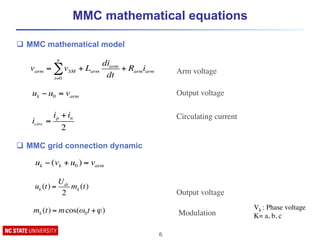
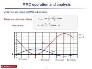
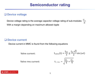
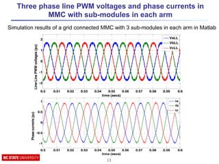
Download as PDF, PPTX


![Modular Multilevel Converter Conventional Control [1]
10
1. An individual capacitor voltage controller
2. The averaging controller
3. The system controller
4. Modulation reference generation
PI PI
1/2
Vc*
Vcu
Ik-‐low
Ik-‐up
Icir*
Icir
VAu*
Total DC voltage controller
PI
Vc*
Vcju
(j=1-‐2n)
±
-1 :-Ik-up , Ik-low ≥ 0
+1 :-Ik-up , Ik-low ≤ 0
VBju*
Individual DC voltage controller
Vmk(k=a,b,c)
PI
i*dref
Vod
iod
PI
i*qref
ω0Leq
ω0Leq
ioq
Voq
3dq/abc
System controller !
[1] Hagiwara, Makoto, and Hirofumi Akagi. "Control and experiment of pulsewidth-modulated modular multilevel
converters." Power electronics, IEEE Transactions on 24.7 (2009): 1737-1746.
VAu*
VBju* Vi/n E/(2n)
Vju*
(j=1-‐n)
dAneg
VAu*
VBju* Vi/n E/(2n)
Vju*
(j=n+1-‐2n)
dAneg
Modulation reference generation](https://image.slidesharecdn.com/modularmultilevelconvertermmctutorial-160417033320/85/Modular-Multilevel-Converter-MMC-tutorial-10-320.jpg)
![MMC modulation methods
11
[1] Wang, Jun, Rolando Burgos, and Dushan Boroyevich. "A survey on the modular multilevel converters—Modeling,
modulation and controls." Energy Conversion Congress and Exposition (ECCE), 2013 IEEE. IEEE, 2013.
Multilevel
Modulation
Fundamental switching
frequency
High switching
frequency
Space vector
PWM
Sinusoidal
PWM
Level shifted
PWM
Phase shifted
PWM
Space vector
control SHENLM
High switching frequency modulation
techniques
ü Suitable for small & large number of sub-modules
ü Lower harmonics
× High losses
Fundamental switching frequency modulation
techniques
ü Suitable for large number of sub-modules
ü Lower losses](https://image.slidesharecdn.com/modularmultilevelconvertermmctutorial-160417033320/85/Modular-Multilevel-Converter-MMC-tutorial-11-320.jpg)
![Passive components design ( Arm inductor
and Sub-module capacitor)
12
L ≥
Vdc
2αmax
!! =
1
(8!!
!
!!!!)
(
!!
3!!!
+ !!")
!!" =
!!
3.!.!.!!.!.!!
!
1 − (
!.!"#$
2
)!
!
!
Ps: three phase apparent power
K: voltage modulation index
Cosφ: power factor
N: number of sub-modules,
ω0 is the fundamental frequency,
VC: mean value of sub-module voltages
ε: sub-module voltage ripple
[1] Tu, Qingrui, et al. "Parameter design principle of the arm inductor in modular multilevel converter based HVDC." Power System Technology (POWERCON),
2010 International Conference on. IEEE, 2010.
[2] Zygmanowski, Marcin, Boguslaw Grzesik, and Radoslaw Nalepa. "Capacitance and inductance selection of the modular multilevel
converter." Power Electronics and Applications (EPE), 2013 15th European Conference on. IEEE, 2013.
1. Limit the circulation current
2. Limit the fault current rise rate
q Criteria to select arm inductor [1]:
q Sub-module capacitor selection [2]:
1. Provide the output power for at least one cycle
If DC link is defective
2. Limit sub-module voltage ripple](https://image.slidesharecdn.com/modularmultilevelconvertermmctutorial-160417033320/85/Modular-Multilevel-Converter-MMC-tutorial-12-320.jpg)
![References
[1] Falahi, Ghazal. "Design, Modeling and Control of Modular Multilevel Converter based HVDC
Systems." PhD Dissertation NCSU (2014).
[2] Falahi, Ghazal, and Alex Q. Huang. "Design consideration of an MMC-HVDC system based on
4500V/4000A emitter turn-off (ETO) thyristor." Energy Conversion Congress and Exposition (ECCE),
2015 IEEE. IEEE, 2015.
[3] Falahi, Ghazal, and Alex Huang. "Control of modular multilevel converter based HVDC systems
during asymmetrical grid faults." Industrial Electronics Society, IECON 2014-40th Annual Conference
of the IEEE. IEEE, 2014.
[4] Falahi, Ghazal, Wensong Yu, and Alex Q. Huang. "THD minimization of modular multilevel
converter with unequal DC values." Energy Conversion Congress and Exposition (ECCE), 2014 IEEE.
IEEE, 2014.
[5] Falahi, Ghazal, and Alex Huang. "Low voltage ride through control of modular multilevel converter
based HVDC systems." Industrial Electronics Society, IECON 2014-40th Annual Conference of the
IEEE. IEEE, 2014.
15](https://image.slidesharecdn.com/modularmultilevelconvertermmctutorial-160417033320/85/Modular-Multilevel-Converter-MMC-tutorial-15-320.jpg)

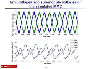
The document discusses the modular multilevel converter (MMC) structure and operation, highlighting its series connection of sub-modules for multi-level output voltage production. It outlines the advantages, such as low total harmonic distortion and scalability, as well as disadvantages, including the need for voltage balancing and monitoring. Additionally, it covers mathematical models and control strategies for MMC operation along with simulation results.


![[1_CV] Model Predictive Control Method for Modular Multilevel Converter Appli...](https://cdn.slidesharecdn.com/ss_thumbnails/1cvmodelpredictivecontrolmethodformodularmultilevelconverterapplications-190418082702-thumbnail.jpg?width=640&height=640&fit=bounds)


