Download to read offline
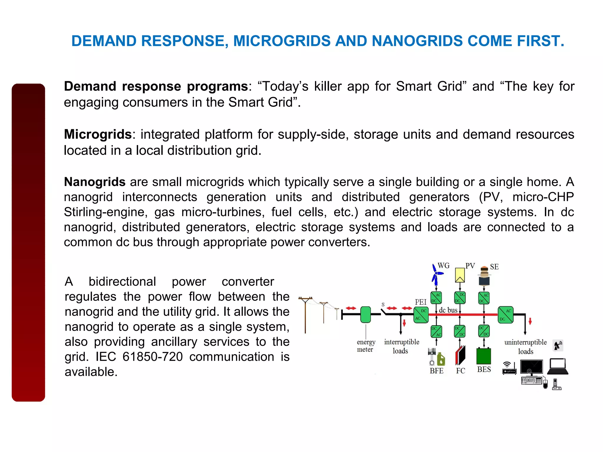
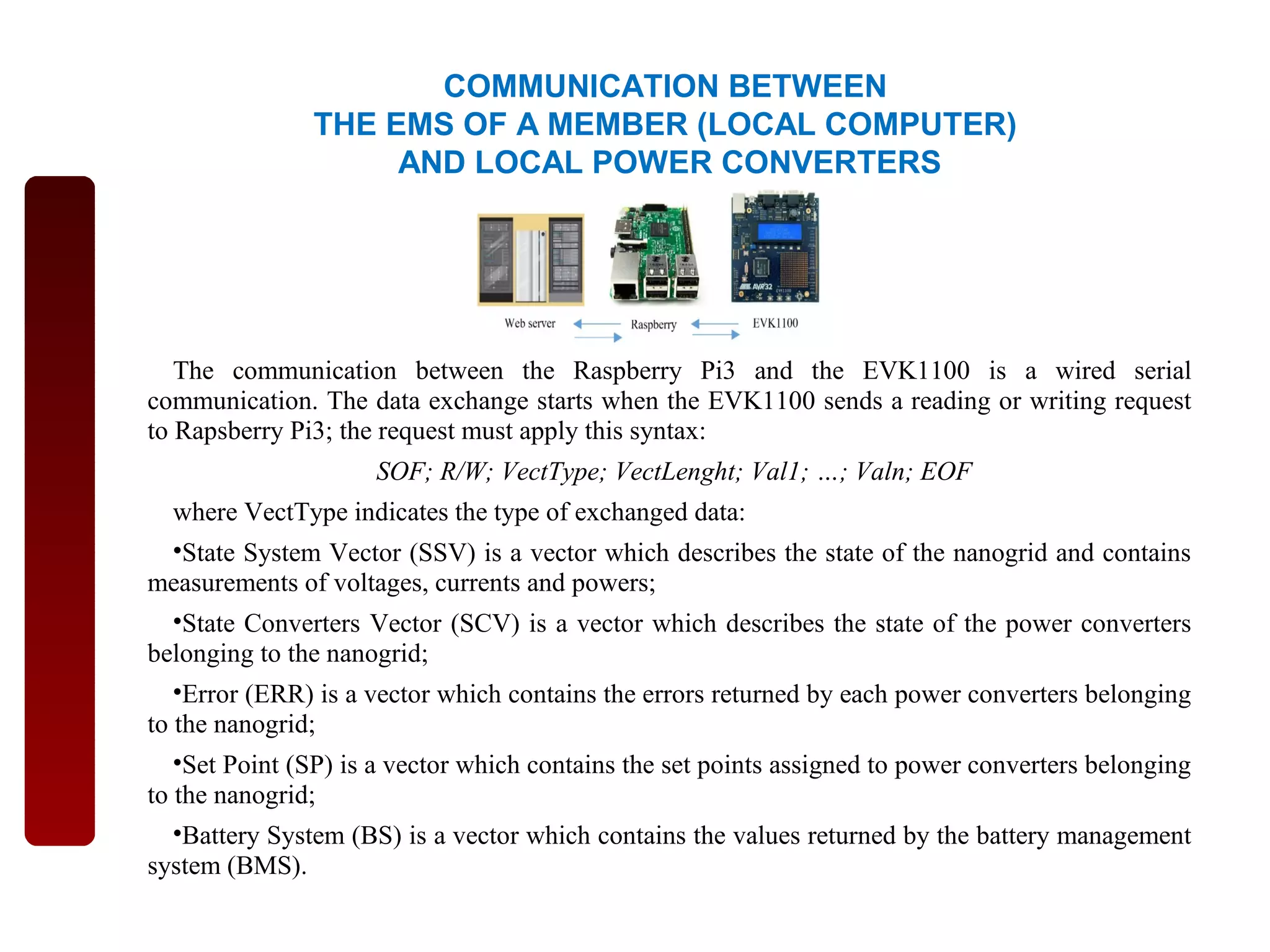
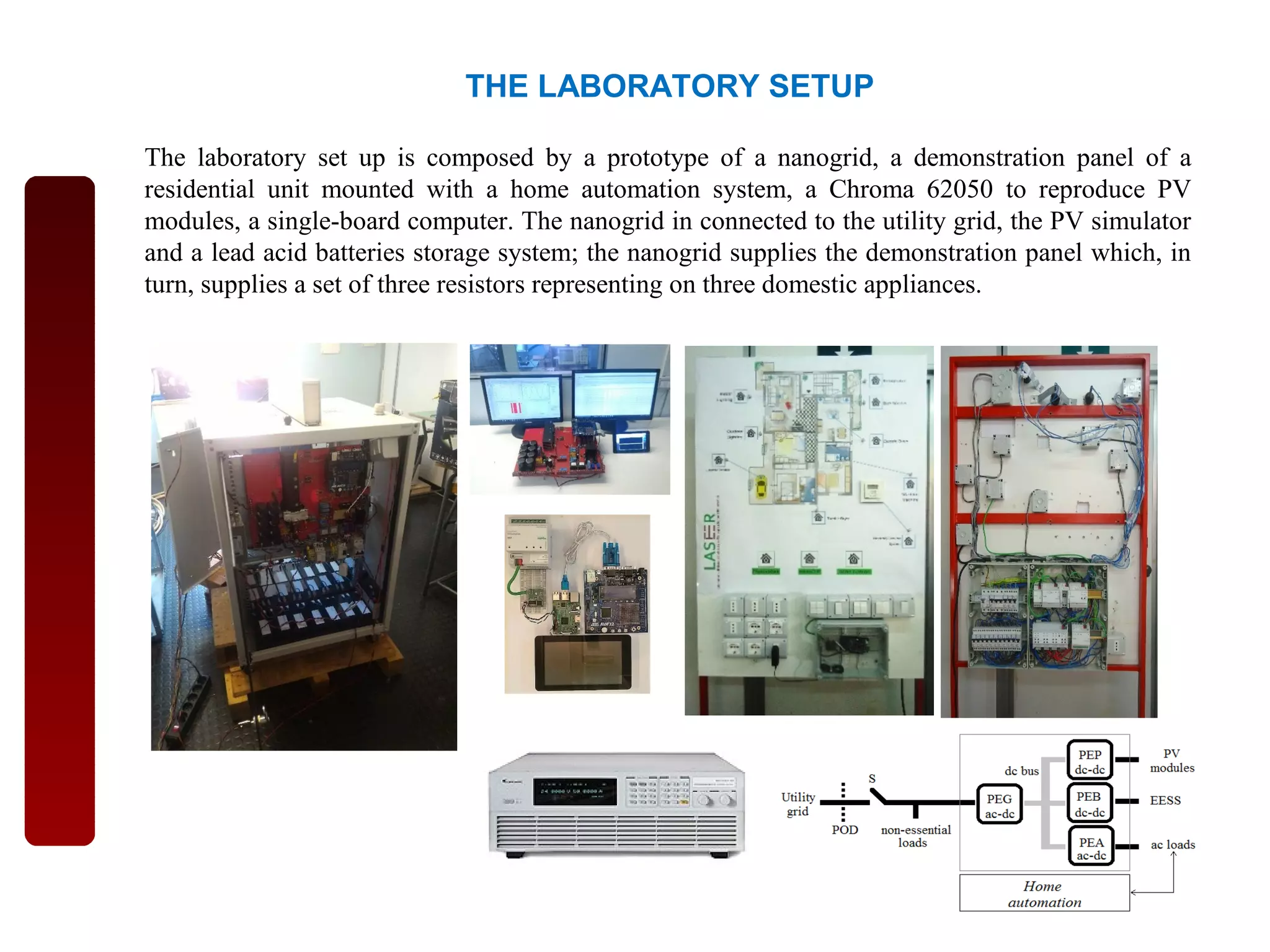
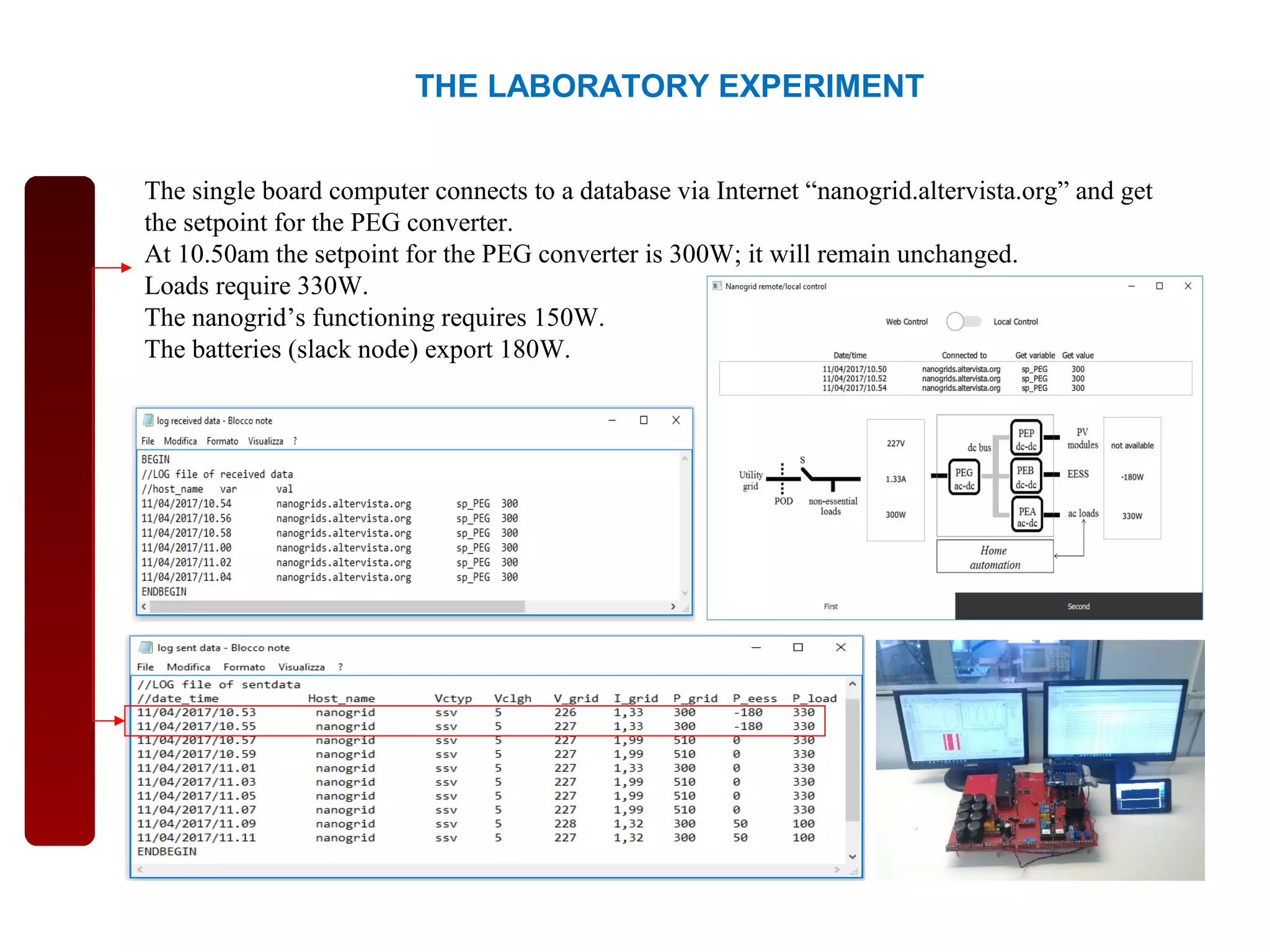
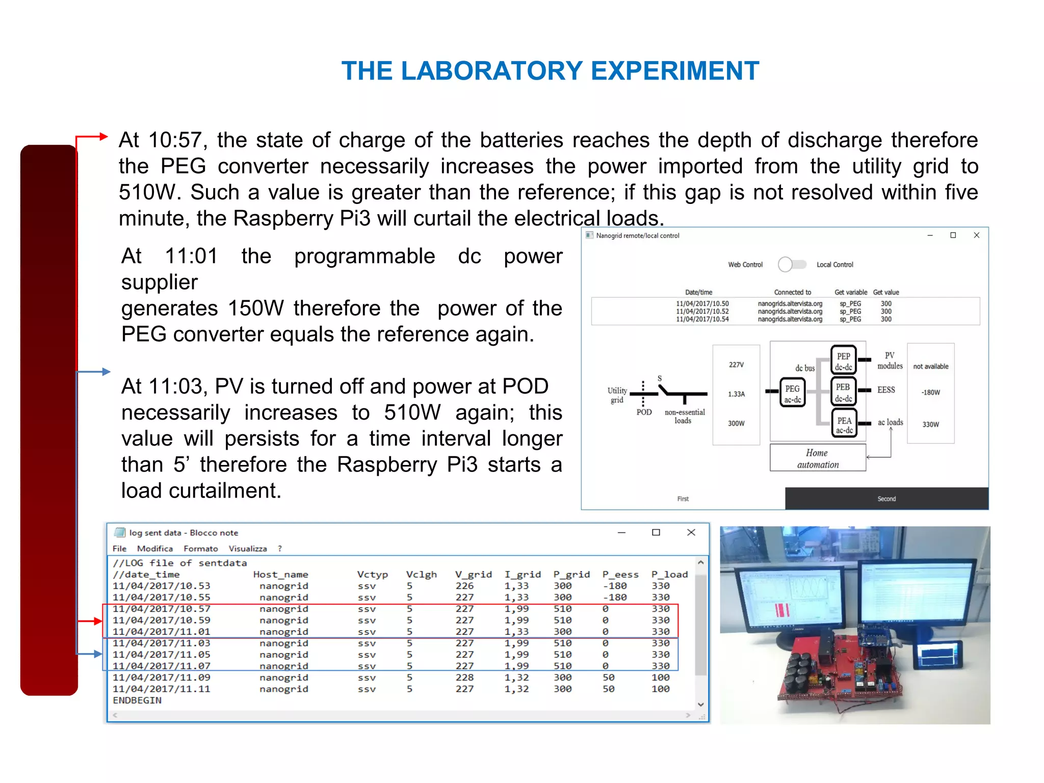
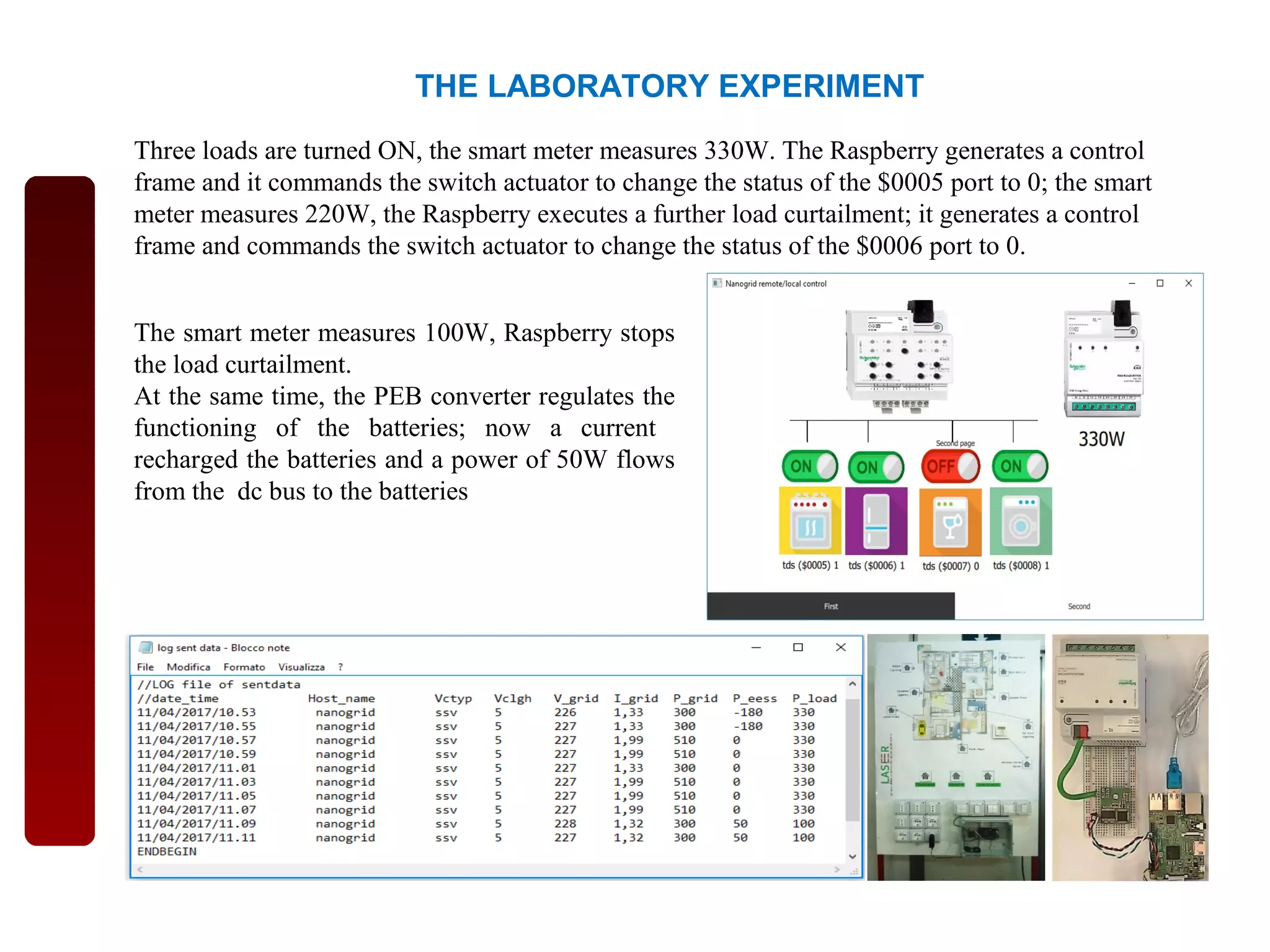

This document summarizes a laboratory setup for remote control of nanogrids as a cost-effective solution. It describes how a nanogrid was prototyped to supply loads and connect to utility grid and storage. A single board computer remotely obtained setpoints from a database to control the power converter between the nanogrid and utility grid. The laboratory experiment demonstrated load curtailment to balance the nanogrid when battery levels dropped or PV generation turned off.


![[IJET V2I3P5] Authors: Jamuna H G, Shobha Hugar](https://cdn.slidesharecdn.com/ss_thumbnails/ijet-v2i3p5-160609051906-thumbnail.jpg?width=640&height=640&fit=bounds)