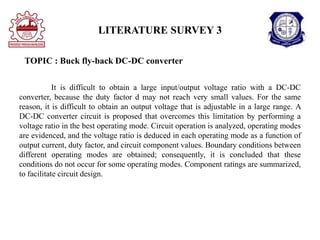
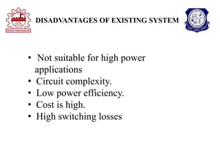
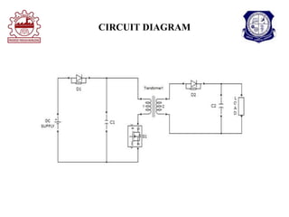
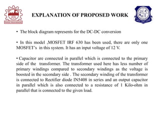
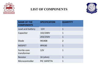
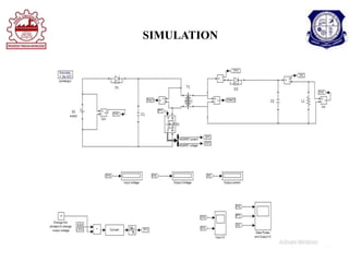
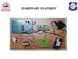
PRESENTED BY :
THAMARAISELVI.P(811721415008)
SUPERVISOR:
Dr. B. KARTHIKEYAN Ph.D
K.RAMAKRISHNAN COLLEGE OF
TECHNOLOGY
TITLE:
COST EFFICIENT ISOLATED DC-DC
CONVERTER FOR ELECTRIC VEHICLE
APPLICATIONS
PRESENTATION OVERVIEW
 Objective
 Literature survey
 Existing system
 Disadvantages of existing system
 Proposed system
 Block diagram of proposed system
 Explanation of proposed system
 Advantages of proposed system
 Simulation
 Hardware snapshot
 Conclusion
 Reference
OBJECTIVE
• To develop a high efficient FLYBACK dc/dc converter with
soft switching.
• To Design a isolated fly-back DC-DC converter with simple
circuit structure in the proposed system
• To boost the output voltage with the help of Isolated DC-DC
converter .
LITERATURE SURVEY 1
TITLE : A review on electric vehicle: Technologies and energy
trading
The energy transition is an essential effort from a variety of sectors and levels
to achieve a larger-renewable integrated civilization. The transportation industry, which
is largely concentrated in urban areas, emits more than 20% of total greenhouse gas
emissions. Consequently research focusing on the integration of electric vehicles (EVs)
powered by renewable energy are currently a viable option for combating climate
change and advancing energy transition. According to current trends, this type of
service will diminish the use of engine in the future months. A study of the global
market scenario for EVs and their future prospects is conducted. Whether energy
storage devices and power electronic converter are properly interfaced determines the
efficiency of EVs. Moreover, we provide our thoughts on what to expect in the near
future in this domain and even the research areas that are still accessible to both
industrial and academics.
LITERATURE SURVEY 2
electric vehicle is a cutting edge technology owing to that the
fact that it mitigates air pollution and increases the fuel efficiency of
vehicle which is the rising demands of the time. Boost converter plays
vital role in electric vehicles. In the work simulation of boost converter
using power MOSFETs has been done in the SIMULINK tool of
MATLAB and voltage and current waveforms are plotted. The result of
simulation matches the theoretical concept which led to development of
hardware of fly-back converter in the power electronics lab.
TITLE : Development of boost converter for electric vehicle
LITERATURE SURVEY 3
TOPIC : Buck fly-back DC-DC converter
It is difficult to obtain a large input/output voltage ratio with a DC-DC
converter, because the duty factor d may not reach very small values. For the same
reason, it is difficult to obtain an output voltage that is adjustable in a large range. A
DC-DC converter circuit is proposed that overcomes this limitation by performing a
voltage ratio in the best operating mode. Circuit operation is analyzed, operating modes
are evidenced, and the voltage ratio is deduced in each operating mode as a function of
output current, duty factor, and circuit component values. Boundary conditions between
different operating modes are obtained; consequently, it is concluded that these
conditions do not occur for some operating modes. Component ratings are summarized,
to facilitate circuit design.
EXISTING DIAGRAM
DISADVANTAGES OF EXISTING SYSTEM
• Not suitable for high power
applications
• Circuit complexity.
• Low power efficiency.
• Cost is high.
• High switching losses
PROPOSED SYSTEM
BLOCK DIAGRAM
CIRCUIT DIAGRAM
EXPLANATION OF PROPOSED WORK
• The block diagram represents for the DC-DC conversion
• In this model ,MOSFET IRF 630 has been used, there are only one
MOSFET’s in this system. It has an input voltage of 12 V.
• Capacitor are connected in parallel which is connected to the primary
side of the transformer. The transformer used here has less number of
primary windings compared to secondary windings as the voltage is
boosted in the secondary side . The secondary winding of the transformer
is connected to Rectifier diode IN5408 in series and an output capacitor
in parallel which is also connected to a resistance of 1 Kilo-ohm in
parallel that is connected to the given load.
EXPLANATION OF PROPOSED WORK
 Through this system ,it became possible to convert 12V to 220
V output through the usage of wide range DC-DC converter. As
this involves boosting we use it specially for Electric vehicles
which is one of the booming technology in terms of Renewable
energy aspects. As compared to existing system it has few
MOSFET’s and diodes but higher efficiency ,that is the
important factor is considered in this model.
ADVANTAGES OF PROPOSED SYSTEM
• Simple circuit structure.
• Low switching losses.
• Reduce ripple current losses both in
input and output side
• High efficiency.
• Reduced switches and passive
element count
LIST OF COMPONENTS
NAME OF THE
COMPONENTS
SPECIFICATION QUANTITY
Lead acid battery 12V 1
Capacitor 102/200V 1
203/250V 1
Diode IN5408 2
MOSFET IRF630 1
Ferrite core
transformer
12V 1
Resistor 1K (ohm) 1
Microcontroller PIC 16F877A 1
SIMULATION
HARDWARE SNAPSHOT
CONCULUSION
• The benefit of this topology : To develop a high efficient
isolated FLYBACK dc/dc converter was developed with
simple circuit structure.
• The results show that the converter can boost the output
voltage. The circuit has shown its capability of high power
applications in proposed system
REFERENCE
[1] Ali Emadi et.al, “Topological overview of hybrid electric and fuel cell Vehicular power
system configurations,” IEEE Vehicular Technology, vol. 54, no.3, May 2005, pp.763-770.
[2] Birca- Galateanu, S, “Buck –flyback DC – DC Converter,” IEEE transaction Nov 1988 pp.
800-807.
[3] C. C. Chan, “The state of the art of electric and hybrid vehicles,” Proceedings of the IEEE, vol.
90, no. 2, February 2002, pp.247-275.
[4] C. C. Chan, “The state of the art of electric, hybrid, and fuel cell Vehicles, Proc. of the IEEE,
vol. 95, no. 4, April 2007, pp.704-718.
[5] Iqbal Hussain, “Electric and Hybrid Vehicle: Design Fundamentals,” Edition, CRC Press,
2003. [5] K.T.Chau and C.C.Chan, “Emerging energy-efficient technologies for hybrid electric
vehicles,” Proceedings of the IEEE, vol. 95, no. 4, April 2007, pp.821-835.
THANK YOU

Presentation on DC-DC converter for EV

  • 1.
    PRESENTED BY : THAMARAISELVI.P(811721415008) SUPERVISOR: Dr.B. KARTHIKEYAN Ph.D K.RAMAKRISHNAN COLLEGE OF TECHNOLOGY TITLE: COST EFFICIENT ISOLATED DC-DC CONVERTER FOR ELECTRIC VEHICLE APPLICATIONS
  • 2.
    PRESENTATION OVERVIEW  Objective Literature survey  Existing system  Disadvantages of existing system  Proposed system  Block diagram of proposed system  Explanation of proposed system  Advantages of proposed system  Simulation  Hardware snapshot  Conclusion  Reference
  • 3.
    OBJECTIVE • To developa high efficient FLYBACK dc/dc converter with soft switching. • To Design a isolated fly-back DC-DC converter with simple circuit structure in the proposed system • To boost the output voltage with the help of Isolated DC-DC converter .
  • 4.
    LITERATURE SURVEY 1 TITLE: A review on electric vehicle: Technologies and energy trading The energy transition is an essential effort from a variety of sectors and levels to achieve a larger-renewable integrated civilization. The transportation industry, which is largely concentrated in urban areas, emits more than 20% of total greenhouse gas emissions. Consequently research focusing on the integration of electric vehicles (EVs) powered by renewable energy are currently a viable option for combating climate change and advancing energy transition. According to current trends, this type of service will diminish the use of engine in the future months. A study of the global market scenario for EVs and their future prospects is conducted. Whether energy storage devices and power electronic converter are properly interfaced determines the efficiency of EVs. Moreover, we provide our thoughts on what to expect in the near future in this domain and even the research areas that are still accessible to both industrial and academics.
  • 5.
    LITERATURE SURVEY 2 electricvehicle is a cutting edge technology owing to that the fact that it mitigates air pollution and increases the fuel efficiency of vehicle which is the rising demands of the time. Boost converter plays vital role in electric vehicles. In the work simulation of boost converter using power MOSFETs has been done in the SIMULINK tool of MATLAB and voltage and current waveforms are plotted. The result of simulation matches the theoretical concept which led to development of hardware of fly-back converter in the power electronics lab. TITLE : Development of boost converter for electric vehicle
  • 6.
    LITERATURE SURVEY 3 TOPIC: Buck fly-back DC-DC converter It is difficult to obtain a large input/output voltage ratio with a DC-DC converter, because the duty factor d may not reach very small values. For the same reason, it is difficult to obtain an output voltage that is adjustable in a large range. A DC-DC converter circuit is proposed that overcomes this limitation by performing a voltage ratio in the best operating mode. Circuit operation is analyzed, operating modes are evidenced, and the voltage ratio is deduced in each operating mode as a function of output current, duty factor, and circuit component values. Boundary conditions between different operating modes are obtained; consequently, it is concluded that these conditions do not occur for some operating modes. Component ratings are summarized, to facilitate circuit design.
  • 7.
  • 8.
    DISADVANTAGES OF EXISTINGSYSTEM • Not suitable for high power applications • Circuit complexity. • Low power efficiency. • Cost is high. • High switching losses
  • 9.
  • 10.
  • 11.
    EXPLANATION OF PROPOSEDWORK • The block diagram represents for the DC-DC conversion • In this model ,MOSFET IRF 630 has been used, there are only one MOSFET’s in this system. It has an input voltage of 12 V. • Capacitor are connected in parallel which is connected to the primary side of the transformer. The transformer used here has less number of primary windings compared to secondary windings as the voltage is boosted in the secondary side . The secondary winding of the transformer is connected to Rectifier diode IN5408 in series and an output capacitor in parallel which is also connected to a resistance of 1 Kilo-ohm in parallel that is connected to the given load.
  • 12.
    EXPLANATION OF PROPOSEDWORK  Through this system ,it became possible to convert 12V to 220 V output through the usage of wide range DC-DC converter. As this involves boosting we use it specially for Electric vehicles which is one of the booming technology in terms of Renewable energy aspects. As compared to existing system it has few MOSFET’s and diodes but higher efficiency ,that is the important factor is considered in this model.
  • 13.
    ADVANTAGES OF PROPOSEDSYSTEM • Simple circuit structure. • Low switching losses. • Reduce ripple current losses both in input and output side • High efficiency. • Reduced switches and passive element count
  • 14.
    LIST OF COMPONENTS NAMEOF THE COMPONENTS SPECIFICATION QUANTITY Lead acid battery 12V 1 Capacitor 102/200V 1 203/250V 1 Diode IN5408 2 MOSFET IRF630 1 Ferrite core transformer 12V 1 Resistor 1K (ohm) 1 Microcontroller PIC 16F877A 1
  • 15.
  • 16.
  • 17.
    CONCULUSION • The benefitof this topology : To develop a high efficient isolated FLYBACK dc/dc converter was developed with simple circuit structure. • The results show that the converter can boost the output voltage. The circuit has shown its capability of high power applications in proposed system
  • 18.
    REFERENCE [1] Ali Emadiet.al, “Topological overview of hybrid electric and fuel cell Vehicular power system configurations,” IEEE Vehicular Technology, vol. 54, no.3, May 2005, pp.763-770. [2] Birca- Galateanu, S, “Buck –flyback DC – DC Converter,” IEEE transaction Nov 1988 pp. 800-807. [3] C. C. Chan, “The state of the art of electric and hybrid vehicles,” Proceedings of the IEEE, vol. 90, no. 2, February 2002, pp.247-275. [4] C. C. Chan, “The state of the art of electric, hybrid, and fuel cell Vehicles, Proc. of the IEEE, vol. 95, no. 4, April 2007, pp.704-718. [5] Iqbal Hussain, “Electric and Hybrid Vehicle: Design Fundamentals,” Edition, CRC Press, 2003. [5] K.T.Chau and C.C.Chan, “Emerging energy-efficient technologies for hybrid electric vehicles,” Proceedings of the IEEE, vol. 95, no. 4, April 2007, pp.821-835.
  • 19.