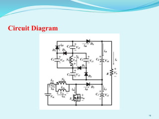
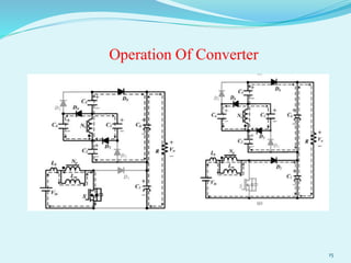
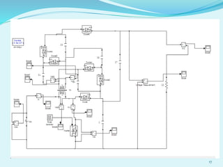
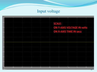
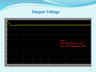
High voltage step- up DC- DC converter using
coupled inductor and switched capacitor
techniques
UNDER THE GUIDENCE OF
Mr P.Hema sundar M-Tech,
Assistant professor.
BATCH NO: EEEK6141508,
V.SANTOSH KUMAR(12K65A0214).
1
Problem Definition
 By connecting the PV solar cell can in series to produce the
high voltages but, the voltage might effect by shadow effect.
 If any one of the PV cell is broken ,the PV array leads to
shutdown the grid.
 Those problems can be overcome by using the converters(DC-
DC converter).
2
CONTENTS:
 Abstract
 Introduction
 Types of converters
 Applications
 Design&analysis
 Simulation of converter
 References
 Pos&peos
 Plan of action 3
ABSTRACT
 The coupled inductor and switched capacitor a technique is proposed in high
voltage step up dc-dc converter.
 The capacitors are charged in parallel and discharged in series by the coupled
inductor, stacking on the output capacitor.
 On performing this project can achieve high step up voltage gain in which
the input dc voltage is 24 volts and we will get output voltage 400 volts with
appropriate duty ratio.
 Besides the voltage spike on the main switch can be clamped, therefore
conduction losses are reduced and hence efficiency will be increased.
4
Introduction
 Renewable energy systems are
more and more widely used to
provide electric energy.
 Energy derived from natural
processes that are replenished at a
faster rate than they are consumed.
 28% of electricity was produced by
Renewable energy sources in over
all production.
5
Modernly converters are classified into two types
Non isolation converters(basic):
 Buck converter
 Boost converter
 Buck-boost converter
Isolation converters:
 Fly back converter
 Forward converter
6
Comparison Of Converters
 Buck converter: step-down, has one switch, simple, high
efficiency greater than 90%, provides one polarity output voltage
and unidirectional output current.
 Boost converter: step-up, has one switch, simple, high
efficiency, provides one polarity output voltage.
 Buck-boost converter: step-up/step-down, has one switch,
simple, high efficiency, provides output voltage polarity reversal.
 Fly back converter: four-quadrant operation, has multiple
switches, can be used in regenerative braking.
7
Methods to produce high voltages
Capacitor means:
 cascaded boost converter techniques
 Voltage-lift techniques
Inductor means:
 coupled inductor techniques
8
HISTORY
Integrated boost- sepic converter
• Limited step up voltage
• Parasitic resistance
Boost converter with coupled inductor
• Active clamp circuit
• Zero-voltage switching
9
Transformer less dc-dc converter
• Conventional dc-dc boost converter has low efficiency
• High step up voltage gain is low
A Generalized high voltage gain boost converter
• High voltage gain
• Lower blocking voltage across the controller switches
10
Applications
 Regulated switch mode power supply,
 Dc motor drives,
 Electric automobiles, trolley cars,
 Marine hoists, mine haulers,
 Personalcomputers, office equipment,
spacecraft power systems, laptop
computers,
 Telecommunications equipment.
11
Subjects related to my project
Power electronics
Power systems
Electrical machines
Electrical circuit analysis
12
Design & Analysis
 The DC to DC converter is used to step up the given input
voltage.
 Input voltage is 24V as mentioned in the proposed converter.
 That volage is step up by using the converter into 400V DC
supply without any ripples at load.
13
Circuit Diagram
14
Operation Of Converter
15
SIMULATION CIRCUIT FOR PROPOSED
CONVERTER
16
17
Input voltage
18
Output Voltage
19
References
 [1] K. B. Park, H. W. Seong, H. S. Kim, G. W. Moon, and M. J. Youn, “Integrated boost-sepic converter for high step-up
applications,” in Proc. Power Electron. Spec. Conf., Rohode, Greece, 2008, pp. 944–950.
 [2] T. F. Wu, Y. S. Lai, J. C. Hung, and Y. M. Chen, “Boost converter with coupled inductors and buck-boost type of
active clamp,” IEEE Trans. Ind. Electron., vol. 55, no. 1, pp. 154–162, Jan. 2008.
 [3] B. Axelrod, Y. Berkovich, S. Tapuchi, and A. Ioinovici, “Steep conversion ration C´ uk, Zeta, and sepic converters
based on a switched coupled inductor cell,” in Proc. IEEE Power Electron. Spec. Conf., Jun. 2008, pp. 3009–3014.
 [4] R. J. Wai, C. Y. Lin, C. Y. Lin, R. Y. Duan, and Y. R. Chang, “High efficiency power conversion system for kilowatt-
level stand-alone generation unit with low input voltage,” IEEE Trans. Ind. Electron., vol. 55, no. 10, pp. 3702–3714,
Oct. 2008.
 [5] V. Scarpa, S. Buso, and G. Spiazzi, “Low-complexity MPPT technique exploiting the PV module MPP locus
characterization,” IEEE Trans. Ind. Electron., vol. 56, no. 5, pp. 1531–1538, May 2009.
 [6] A. Timbus, M. Liserre, R. Teodorescu, P. Rodriguez, and F. Blaabjerg, “Evaluation of current controllers for
distributed power generation systems,” IEEE Trans. Power Electron., vol. 24, no. 3, pp. 654–664, Mar. 2009.
 [7] L. S. Yang, T. J. Liang, and J. F. Chen, “Transformer-less dc-dc converter with high voltage gain,” IEEE Trans. Ind.
Electron., vol. 56, no. 8, pp. 3144–3152, Aug. 2009.
 [8] S. V. Araujo, R. P. Torrico-Bascope, and G. V. Torrico-Bascope, “Highly efficient high step-up converter for fuel-cell
power processing based on three-state commutation cell,” IEEE Trans. Ind. Electron., vol. 57, no. 6, pp. 1987–1997, Jun.
2010.
 [9] C. L. Chen, Y. Wang, J. S. Lai, Y. S. Lee, and D. Martin, “Design of parallel inverters for smooth mode transfer micro
grid applications,” IEEE Trans. Power Electron., vol. 25, no. 1, pp. 6–15, Jan. 2010.
 [10] S. K. Changchien, T. J. Liang, J. F. Chen, and L. S. Yang, “Novel high step-up dc-dc converter for fuel cell energy
conversion system,” IEEE Trans. Ind. Electron. vol. 57, no. 6, pp. 2007–2017, Jun. 2010.
20
POS:
Program Educational Objectives Relevance
Graduates shall have good technical knowledge
and skills in the area of Electrical & Electronics
engineering to fulfill the needs of industry and
society.
We got good
technical skills
by doing this
project
Graduates shall have research capabilities to
achieve success in their chosen fields with team
work
We got more
knowledge about
mentioned fields
Graduates shall be successful engineers with
lifelong learning, right attitude and Ethics
21
PEOS:
Program Outcomes Relevance
An ability to apply knowledge of mathematics,
science, and engineering.
While doing a design of converter
An ability to design and conduct experiments, as
well as to analyze and interpret data.
We can Conduct more experiments in MAT-
LAB
An ability to design a system, component, or
process to meet desired needs within realistic
Constraints such as economic, environmental,
social, political, ethical, health and safely.
Manufacturability and sustainability.
Converter is used for environmental,scoitey
needs to achieve high voltage
An ability to function on multi-disciplinary teams
Maths,science,engineering and management
An ability to identify, formulate, and solve
engineering problems
Identified problem by using non renewable
energy sources
An understanding of professional and ethical
responsibility
22
PEOS:
Program Educational Objectives Relevance
An ability to communicate effectively
The broad education necessary to understand the impact of
engineering solutions in a global, economic, environmental and
societal context
A recognition of the need for, and an ability to engage in life-long
learning
A knowledge of contemporary issues
An ability to use the techniques, skills, and modern engineering tools
necessary for engineering practice.
We can use more
techniques,skills noting but
coulped inductor.
An ability to carry out research in the field of Power Electronics and
Power Systems resulting in product development.
Why because, my project is
power electronics oriented
23
CONCLUSION
 To have large high step-up voltage gain, some converters have
been proposed which use the coupled-inductor as a transformer
in fly back and forward converter.
 To get large efficiency of converter, reduces the conduction
losses and voltage spikes occurs across the power switch.
24
PLAN OFACTION
S.NO ACTION STEPS COMPLETION DATE
1 Title and Abstract 28/07/2014
2 Literature survey and po’s and peo’s 18/09/2014
3. Modeling of circuit 15/10/2014
4 Simulation of converter 29/12/2014
5 Fabrication of converter 28/01/2015
6 Results & documentation thesis with rough
copy
27/02/2015
7 Thesis submission(softcopy and hardcopy) 15/03/2015
25
26
27

high voltage step-up dc-dc converter with coupled inductor

  • 1.
    High voltage step-up DC- DC converter using coupled inductor and switched capacitor techniques UNDER THE GUIDENCE OF Mr P.Hema sundar M-Tech, Assistant professor. BATCH NO: EEEK6141508, V.SANTOSH KUMAR(12K65A0214). 1
  • 2.
    Problem Definition  Byconnecting the PV solar cell can in series to produce the high voltages but, the voltage might effect by shadow effect.  If any one of the PV cell is broken ,the PV array leads to shutdown the grid.  Those problems can be overcome by using the converters(DC- DC converter). 2
  • 3.
    CONTENTS:  Abstract  Introduction Types of converters  Applications  Design&analysis  Simulation of converter  References  Pos&peos  Plan of action 3
  • 4.
    ABSTRACT  The coupledinductor and switched capacitor a technique is proposed in high voltage step up dc-dc converter.  The capacitors are charged in parallel and discharged in series by the coupled inductor, stacking on the output capacitor.  On performing this project can achieve high step up voltage gain in which the input dc voltage is 24 volts and we will get output voltage 400 volts with appropriate duty ratio.  Besides the voltage spike on the main switch can be clamped, therefore conduction losses are reduced and hence efficiency will be increased. 4
  • 5.
    Introduction  Renewable energysystems are more and more widely used to provide electric energy.  Energy derived from natural processes that are replenished at a faster rate than they are consumed.  28% of electricity was produced by Renewable energy sources in over all production. 5
  • 6.
    Modernly converters areclassified into two types Non isolation converters(basic):  Buck converter  Boost converter  Buck-boost converter Isolation converters:  Fly back converter  Forward converter 6
  • 7.
    Comparison Of Converters Buck converter: step-down, has one switch, simple, high efficiency greater than 90%, provides one polarity output voltage and unidirectional output current.  Boost converter: step-up, has one switch, simple, high efficiency, provides one polarity output voltage.  Buck-boost converter: step-up/step-down, has one switch, simple, high efficiency, provides output voltage polarity reversal.  Fly back converter: four-quadrant operation, has multiple switches, can be used in regenerative braking. 7
  • 8.
    Methods to producehigh voltages Capacitor means:  cascaded boost converter techniques  Voltage-lift techniques Inductor means:  coupled inductor techniques 8
  • 9.
    HISTORY Integrated boost- sepicconverter • Limited step up voltage • Parasitic resistance Boost converter with coupled inductor • Active clamp circuit • Zero-voltage switching 9
  • 10.
    Transformer less dc-dcconverter • Conventional dc-dc boost converter has low efficiency • High step up voltage gain is low A Generalized high voltage gain boost converter • High voltage gain • Lower blocking voltage across the controller switches 10
  • 11.
    Applications  Regulated switchmode power supply,  Dc motor drives,  Electric automobiles, trolley cars,  Marine hoists, mine haulers,  Personalcomputers, office equipment, spacecraft power systems, laptop computers,  Telecommunications equipment. 11
  • 12.
    Subjects related tomy project Power electronics Power systems Electrical machines Electrical circuit analysis 12
  • 13.
    Design & Analysis The DC to DC converter is used to step up the given input voltage.  Input voltage is 24V as mentioned in the proposed converter.  That volage is step up by using the converter into 400V DC supply without any ripples at load. 13
  • 14.
  • 15.
  • 16.
    SIMULATION CIRCUIT FORPROPOSED CONVERTER 16
  • 17.
  • 18.
  • 19.
  • 20.
    References  [1] K.B. Park, H. W. Seong, H. S. Kim, G. W. Moon, and M. J. Youn, “Integrated boost-sepic converter for high step-up applications,” in Proc. Power Electron. Spec. Conf., Rohode, Greece, 2008, pp. 944–950.  [2] T. F. Wu, Y. S. Lai, J. C. Hung, and Y. M. Chen, “Boost converter with coupled inductors and buck-boost type of active clamp,” IEEE Trans. Ind. Electron., vol. 55, no. 1, pp. 154–162, Jan. 2008.  [3] B. Axelrod, Y. Berkovich, S. Tapuchi, and A. Ioinovici, “Steep conversion ration C´ uk, Zeta, and sepic converters based on a switched coupled inductor cell,” in Proc. IEEE Power Electron. Spec. Conf., Jun. 2008, pp. 3009–3014.  [4] R. J. Wai, C. Y. Lin, C. Y. Lin, R. Y. Duan, and Y. R. Chang, “High efficiency power conversion system for kilowatt- level stand-alone generation unit with low input voltage,” IEEE Trans. Ind. Electron., vol. 55, no. 10, pp. 3702–3714, Oct. 2008.  [5] V. Scarpa, S. Buso, and G. Spiazzi, “Low-complexity MPPT technique exploiting the PV module MPP locus characterization,” IEEE Trans. Ind. Electron., vol. 56, no. 5, pp. 1531–1538, May 2009.  [6] A. Timbus, M. Liserre, R. Teodorescu, P. Rodriguez, and F. Blaabjerg, “Evaluation of current controllers for distributed power generation systems,” IEEE Trans. Power Electron., vol. 24, no. 3, pp. 654–664, Mar. 2009.  [7] L. S. Yang, T. J. Liang, and J. F. Chen, “Transformer-less dc-dc converter with high voltage gain,” IEEE Trans. Ind. Electron., vol. 56, no. 8, pp. 3144–3152, Aug. 2009.  [8] S. V. Araujo, R. P. Torrico-Bascope, and G. V. Torrico-Bascope, “Highly efficient high step-up converter for fuel-cell power processing based on three-state commutation cell,” IEEE Trans. Ind. Electron., vol. 57, no. 6, pp. 1987–1997, Jun. 2010.  [9] C. L. Chen, Y. Wang, J. S. Lai, Y. S. Lee, and D. Martin, “Design of parallel inverters for smooth mode transfer micro grid applications,” IEEE Trans. Power Electron., vol. 25, no. 1, pp. 6–15, Jan. 2010.  [10] S. K. Changchien, T. J. Liang, J. F. Chen, and L. S. Yang, “Novel high step-up dc-dc converter for fuel cell energy conversion system,” IEEE Trans. Ind. Electron. vol. 57, no. 6, pp. 2007–2017, Jun. 2010. 20
  • 21.
    POS: Program Educational ObjectivesRelevance Graduates shall have good technical knowledge and skills in the area of Electrical & Electronics engineering to fulfill the needs of industry and society. We got good technical skills by doing this project Graduates shall have research capabilities to achieve success in their chosen fields with team work We got more knowledge about mentioned fields Graduates shall be successful engineers with lifelong learning, right attitude and Ethics 21
  • 22.
    PEOS: Program Outcomes Relevance Anability to apply knowledge of mathematics, science, and engineering. While doing a design of converter An ability to design and conduct experiments, as well as to analyze and interpret data. We can Conduct more experiments in MAT- LAB An ability to design a system, component, or process to meet desired needs within realistic Constraints such as economic, environmental, social, political, ethical, health and safely. Manufacturability and sustainability. Converter is used for environmental,scoitey needs to achieve high voltage An ability to function on multi-disciplinary teams Maths,science,engineering and management An ability to identify, formulate, and solve engineering problems Identified problem by using non renewable energy sources An understanding of professional and ethical responsibility 22
  • 23.
    PEOS: Program Educational ObjectivesRelevance An ability to communicate effectively The broad education necessary to understand the impact of engineering solutions in a global, economic, environmental and societal context A recognition of the need for, and an ability to engage in life-long learning A knowledge of contemporary issues An ability to use the techniques, skills, and modern engineering tools necessary for engineering practice. We can use more techniques,skills noting but coulped inductor. An ability to carry out research in the field of Power Electronics and Power Systems resulting in product development. Why because, my project is power electronics oriented 23
  • 24.
    CONCLUSION  To havelarge high step-up voltage gain, some converters have been proposed which use the coupled-inductor as a transformer in fly back and forward converter.  To get large efficiency of converter, reduces the conduction losses and voltage spikes occurs across the power switch. 24
  • 25.
    PLAN OFACTION S.NO ACTIONSTEPS COMPLETION DATE 1 Title and Abstract 28/07/2014 2 Literature survey and po’s and peo’s 18/09/2014 3. Modeling of circuit 15/10/2014 4 Simulation of converter 29/12/2014 5 Fabrication of converter 28/01/2015 6 Results & documentation thesis with rough copy 27/02/2015 7 Thesis submission(softcopy and hardcopy) 15/03/2015 25
  • 26.
  • 27.