SIMULATION OF MULTIMODE DC-DC CONVERTER FOR EV APPLICATIONS
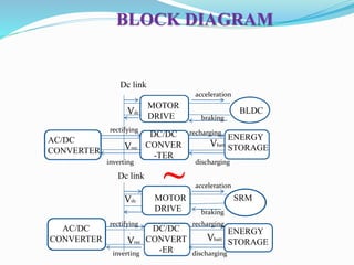
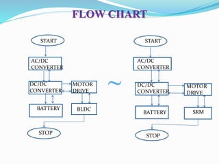
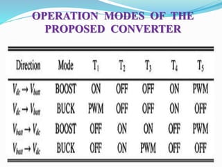
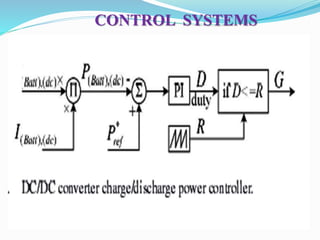
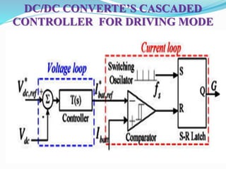
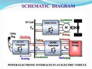
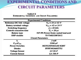
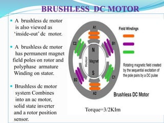
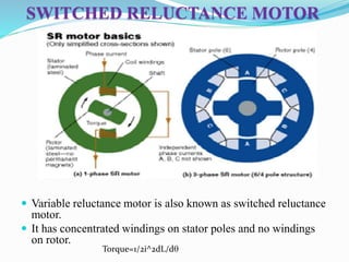
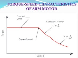
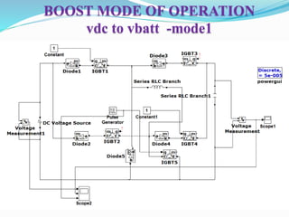
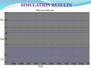
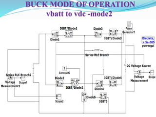
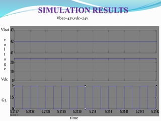
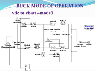
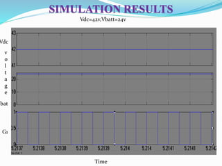
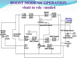
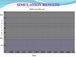
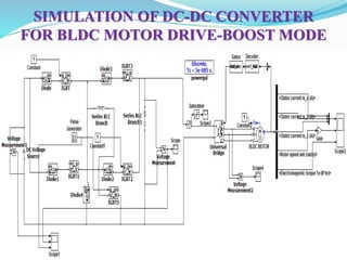
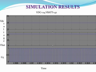
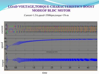
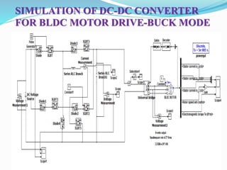
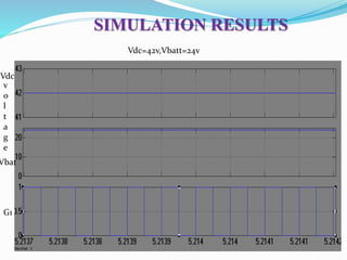
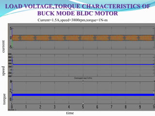
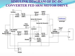
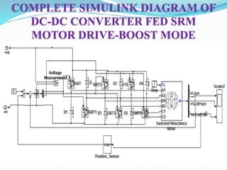
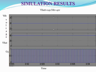
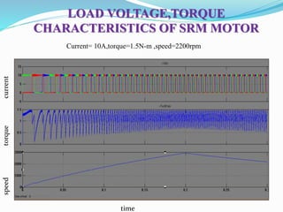
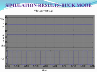
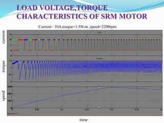
This document describes a proposed universal bidirectional DC-DC power converter that can interface an energy storage device (such as a battery) with a motor drive for electric vehicles. The converter can step up or step down voltages in both directions with bidirectional power flow. It is capable of operating in all modes needed for applications like charging, accelerating, braking and discharging. Simulation results show it efficiently operates switched reluctance and BLDC motors in different voltage scenarios. The proposed converter reduces costs and components compared to using separate buck and boost converters.
SIMULATION OF MULTIMODE DC-DC CONVERTER FOR EV APPLICATIONS
2.
ABSTRACT
This studyfocuses on a universal power electronic
interface that can be utilized in any type of the electric
vehicles, hybrid electric vehicles, and plug-in hybrid
electric vehicles.
Basically, the proposed converter interfaces the energy
storage device of the vehicle with the motor drive.
The proposed converter is capable of operating in all
directions in buck or boost modes with a non inverted
output voltage and bidirectional power flow.
INTRODUCTION
The proposedtopology is suitable not only for conversion
approaches but also is a good candidate to reduce the
number of dc/dc converters from two to one in
commercially available vehicles.
DC-DC converters are widely preferred in order to obtain
quality power,improves efficiency.
By using SRM motor drive high speeds can be obtained.
PROBLEM DESCRIPTION
Indriving mode, usually the battery voltage is
stepped-up during acceleration. DC link voltage is
stepped-down during braking, where Vdc>Vbatt.
If motor drive’s nominal voltage is less than battery’s
nominal voltage,Vdc<Vbatt, the battery voltage should
be stepped-down during acceleration and the dc link
voltage should be stepped-up during regenerative
braking.
8.
PROBLEM SOLUTION
Whenall these possibilities are considered, the need for a
universal bidirectional dc/dc converter is obvious which
should be capable of operating in all-directions with
stepping-up and stepping-down functionalities.
Such a universal converter would meet all the needs of the
auto industry. The proposed converter in this manuscript
not only fulfils these conditions, but also can be utilized
for retrofit conversion of conventional cars to HEVs as
well as the HEV to PHEV conversions.
9.
OPERATING MODES
Case 1:Vdc<Vbatt
Modes
1.Vdc→Vbatt Boost Mode for Plug-in Charging and
Regenerative Braking:
2.Vbatt→Vdc Buck Mode for Plug-in Discharging and
Acceleration:
Case 2:Vdc>Vbatt
Modes
3.Vdc→Vbatt Buck Mode for Plug-in Charging and
Regenerative Braking:
4.Vbatt→Vdc Boost Mode for Plug-in Discharging
and Acceleration:
BRUSHLESS DC MOTOR
A brushless dc motor
is also viewed as
‘inside-out’ dc motor.
A brushless dc motor
has permanent magnet
field poles on rotor and
polyphase armature
Winding on stator.
Brushless dc motor
system Combines
into an ac motor,
solid state inverter
and a rotor position
sensor.
Torque=3/2KIm
20.
SWITCHED RELUCTANCE MOTOR
Variable reluctance motor is also known as switched reluctance
motor.
It has concentrated windings on stator poles and no windings
on rotor.
Torque=1/2i^2dL/dq
EFFICIENCY -LOSS ANALYSISAND
COMPARISIONS WITH EXISTING
APPROACHES
The proposed converter is compared with fundamental
buck or boost dc/dc converters for each of its modes, the
switching losses are identical since the proposed converter
has only one switch in PWM mode in all of the modes.
The additional conduction loss is mainly due to the
additional switches or diodes in the current flow paths of
the proposed converter.
31.
When theconverter is operated in boost mode from dc
link to the battery, the switching losses are the same,diode
conduction loss would be PD = vF .IF , while the IGBT
conduction loss would be PT = vCE(SAT).ICE. Change in
losses can be expressed as
ΔPloss,1 = PD1 + PT 1 + PT 4. (1)
When the dc/dc converter is operated in buck mode from
battery to the dc link, the additional conduction loss is due
to diode D2,D3 and the switch T2.
ΔPloss,2 = PD2 + PD3 + PT 2. (2)
32.
Similarly, whendc/dc converter is operated in buck mode
from dclink to the battery, additional conduction losses
occur due to diodes D1 and D4 and the conducting switch
T4 is given as
ΔPloss,4 = PT 4 + PD1 + PD4. (3)
When the dc/dc converter is operated in boost mode from
battery to the dc link,conduction losses are due to a pair of
additional conducting switches T2 , T3 and the diode D3.
ΔPloss,3 = PT 2 + PT 3 + PD3. (4)
33.
To estimatecomparative change in efficiency, η is identified as
efficiency of the conventional buck or boost mode and η!is
defined as the efficiency of the proposed converter with
additional losses.
If Po is the output power and Pin is the input power, the change in
the efficiency can be obtained as
Δη = η- η!= P0/PIN – P0/(PIN+P LOSS) (5)
where IGBT’s VCE(SAT) is 1.6 V, whereas diode’s VF is 2.1 V
Vdc → Vbatt boost mode, where the input voltage = 169.7 V, output
voltage is 300 V, and the average input and output currents are
15.48 and 8.5 A
34.
Therefore, thechange in efficiency for this mode can be
expressed as
= 0.9707 − 0.9452 = 2.55%. (6)
When stepping-down the battery voltage,inVbatt →Vdc buck
mode, input voltage is 300 V, output voltage is 169.7 V,
and the input and output currents are 8.5 and 14.62A.
Under these conditions, the change in efficiency can be
calculated as
35.
= 0.9729 −0.9462 = 2.67%. (7)
For the rest of the operation modes, the analyses are the same, for
3 and 4 modes. Therefore, change in efficiencies in modes 1 and
2 are identical to that of modes 3 and 4.
Considering thesebuck and boost functionalities, the proposed
converter reduces the number of dc/dc converters in all-electric
vehicle.
In order to provide the same functionality, four dc/dc converters
would be needed, two of them would be boost dc/dc converters
and other two of them would be buck dc/dc converters and four
inductors are needed.
The proposed converter adds only two more semiconductor
devices,however it reduces the number of inductors from four to
one as it is compared to the two buck and two boost converter’s
approach.
Inductors would require much more space as it is compared to
the space requirement of two switches. Therefore, one can state
that the proposed dc/dc converter would reduce both the cost and
the size of the conventional approach for the same functionality
basis.
ADVANTAGES
High speedscan be obtained.
SRM motor is not costlier as there rotor is not a permanent
magnet.
VRM is operated from unidirectional drive circuits,so cost
is reduced.
The noninverted operation capability of the proposed
converter totally eliminates the need for an inverting
transformer,which reduces the overall size and cost.
Increases the flexibility.
58.
CONCLUSION
This studypresents a novel dc/dc converter structure that
is suitable for both industrial needs and the retrofit electric
vehicle conversion approaches.
The proposed topology is suitable not only for conversion
approaches but also is a good candidate to reduce the
number of dc/dc converters from two to one in
commercially available vehicles.
By using SRM motor drive high speeds can be obtained
and srm motor is not costlier.
59.
FUTURE SCOPE
Inthe future, a full-scale dc/dc converter will be built for
a typical mid-size sedan vehicle and the converter will be
implemented for a real-world application.
Adjustable speed drive systems based on VRMs are
becoming competitive with converter fed dc drives and
inverter controlled induction motor drives.