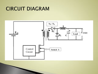
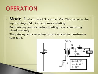
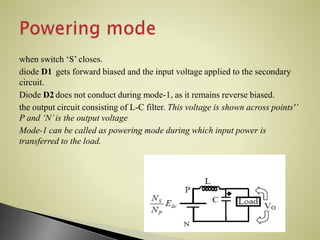
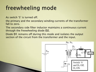
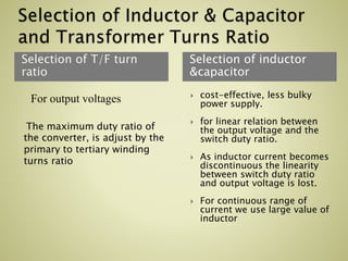
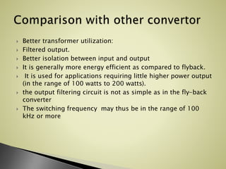
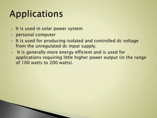
Group members
Muhammad zeeshan#05
Qasim tayyab #06
 The forward converter is a dc to dc
converter that use a transformer to increase
or decrease the output voltage (depending
on the transformer ratio) and provide
galvanic isolation for the load.
• Mode-1 when switch S is turned ON. This connects the
input voltage, Edc, to the primary winding.
• Both primary and secondary windings start conducting
simultaneously.
• The primary and secondary current related to transformer
turn ratio.
when switch ‘S’ closes.
diode D1 gets forward biased and the input voltage applied to the secondary
circuit.
Diode D2 does not conduct during mode-1, as it remains reverse biased.
the output circuit consisting of L-C filter. This voltage is shown across points'’
P and ‘N’is the output voltage
Mode-1 can be called as powering mode during which input power is
transferred to the load.
As switch ‘S’ is turned off.
the primary and the secondary winding currents of the transformer
fall to zero.
The secondary side filter inductor maintains a continuous current
through the freewheeling diode D2.
Diode D1 remains off during this mode and isolates the output
section of the circuit from the transformer and the input.
Selection of T/F turn
ratio
Selection of inductor
&capacitor
For output voltages
The maximum duty ratio of
the converter, is adjust by the
primary to tertiary winding
turns ratio
 cost-effective, less bulky
power supply.
 for linear relation between
the output voltage and the
switch duty ratio.
 As inductor current becomes
discontinuous the linearity
between switch duty ratio
and output voltage is lost.
 For continuous range of
current we use large value of
inductor
 Better transformer utilization:
 Filtered output.
 Better isolation between input and output
 It is generally more energy efficient as compared to flyback.
 It is used for applications requiring little higher power output
(in the range of 100 watts to 200 watts).
 the output filtering circuit is not as simple as in the fly-back
converter
 The switching frequency may thus be in the range of 100
kHz or more
 It is used in solar power system
 personal computer
 It is used for producing isolated and controlled dc voltage
from the unregulated dc input supply.
 It is generally more energy efficient and is used for
applications requiring little higher power output (in the range
of 100 watts to 200 watts).
Forward convertor

Forward convertor

  • 1.
  • 2.
     The forwardconverter is a dc to dc converter that use a transformer to increase or decrease the output voltage (depending on the transformer ratio) and provide galvanic isolation for the load.
  • 4.
    • Mode-1 whenswitch S is turned ON. This connects the input voltage, Edc, to the primary winding. • Both primary and secondary windings start conducting simultaneously. • The primary and secondary current related to transformer turn ratio.
  • 5.
    when switch ‘S’closes. diode D1 gets forward biased and the input voltage applied to the secondary circuit. Diode D2 does not conduct during mode-1, as it remains reverse biased. the output circuit consisting of L-C filter. This voltage is shown across points'’ P and ‘N’is the output voltage Mode-1 can be called as powering mode during which input power is transferred to the load.
  • 6.
    As switch ‘S’is turned off. the primary and the secondary winding currents of the transformer fall to zero. The secondary side filter inductor maintains a continuous current through the freewheeling diode D2. Diode D1 remains off during this mode and isolates the output section of the circuit from the transformer and the input.
  • 7.
    Selection of T/Fturn ratio Selection of inductor &capacitor For output voltages The maximum duty ratio of the converter, is adjust by the primary to tertiary winding turns ratio  cost-effective, less bulky power supply.  for linear relation between the output voltage and the switch duty ratio.  As inductor current becomes discontinuous the linearity between switch duty ratio and output voltage is lost.  For continuous range of current we use large value of inductor
  • 8.
     Better transformerutilization:  Filtered output.  Better isolation between input and output  It is generally more energy efficient as compared to flyback.  It is used for applications requiring little higher power output (in the range of 100 watts to 200 watts).  the output filtering circuit is not as simple as in the fly-back converter  The switching frequency may thus be in the range of 100 kHz or more
  • 9.
     It isused in solar power system  personal computer  It is used for producing isolated and controlled dc voltage from the unregulated dc input supply.  It is generally more energy efficient and is used for applications requiring little higher power output (in the range of 100 watts to 200 watts).