The document discusses serial communications and common interface standards. It covers:
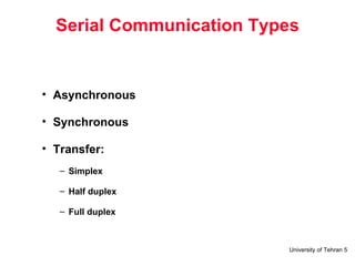
1) Types of serial communication including asynchronous and synchronous transfer, and simplex, half duplex, and full duplex transfer types.
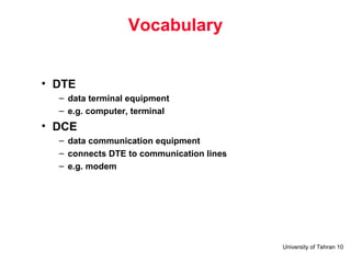
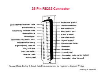
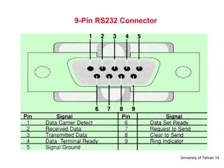
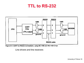
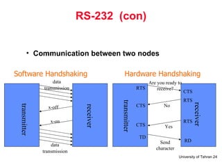
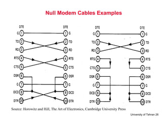
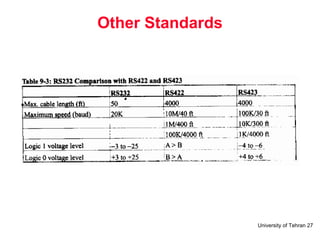
2) The RS-232 standard for serial communication interfaces between DTE and DCE devices. It specifies voltage levels, connector types, and signal functions.
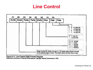
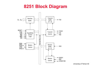
3) Common interface chips like the 8250/16450/16550 UART used for asynchronous communication and flow control between devices.