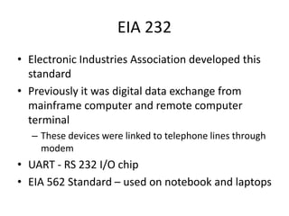
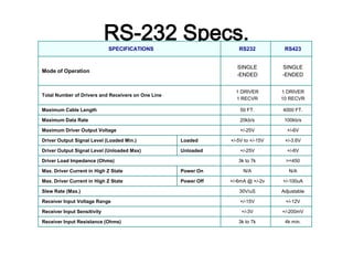
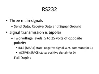
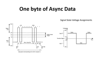
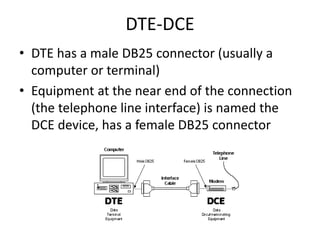
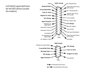
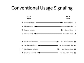
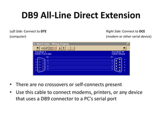
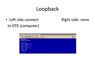
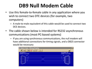
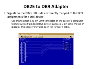
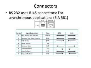
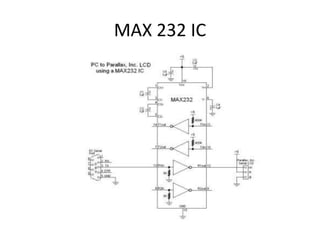
RS 232 Interface
EIA 232
• Electronic Industries Association developed this
standard
• Previously it was digital data exchange from
mainframe computer and remote computer
terminal
– These devices were linked to telephone lines through
modem
• UART - RS 232 I/O chip
• EIA 562 Standard – used on notebook and laptops
RS-232 Specs.SPECIFICATIONS RS232 RS423
Mode of Operation
SINGLE
-ENDED
SINGLE
-ENDED
Total Number of Drivers and Receivers on One Line
1 DRIVER
1 RECVR
1 DRIVER
10 RECVR
Maximum Cable Length 50 FT. 4000 FT.
Maximum Data Rate 20kb/s 100kb/s
Maximum Driver Output Voltage +/-25V +/-6V
Driver Output Signal Level (Loaded Min.) Loaded +/-5V to +/-15V +/-3.6V
Driver Output Signal Level (Unloaded Max) Unloaded +/-25V +/-6V
Driver Load Impedance (Ohms) 3k to 7k >=450
Max. Driver Current in High Z State Power On N/A N/A
Max. Driver Current in High Z State Power Off +/-6mA @ +/-2v +/-100uA
Slew Rate (Max.) 30V/uS Adjustable
Receiver Input Voltage Range +/-15V +/-12V
Receiver Input Sensitivity +/-3V +/-200mV
Receiver Input Resistance (Ohms) 3k to 7k 4k min.
RS232
• Three main signals
– Send Data, Receive Data and Signal Ground
• Signal transmission is bipolar
– Two voltage levels: 5 to 25 volts of opposite
polarity
• IDLE (MARK) state: negative signal w.r.t. common (for 1)
• ACTIVE (SPACE)state: positive signal (for 0)
– Full Duplex
One byte of Async Data
Signal State Voltage Assignments
DTE-DCE
• DTE has a male DB25 connector (usually a
computer or terminal)
• Equipment at the near end of the connection
(the telephone line interface) is named the
DCE device, has a female DB25 connector
Full EIA232 signal
definition for the DTE
device (usually the PC)
Full EIA232 signal definition
for the DCE device (usually
the modem)
• Secondary channel includes a duplicate set of flow-
control signals
– provides for management of the remote modem
– Enabling baud rate to be changed on the fly
– Retransmission to be requested if a parity error is detected
– Other control functions
• Secondary channel operated at a low baud rate
compared to primary channel to ensure reliability in
the control path
• It may operate as either simplex or half-duplex or full-
duplex channel depending on the capabilities of
modem
Conventional Usage Signaling
Signal Definitions
• Signal functions in the EIA232 standard can be subdivided into six
categories
– Signal ground and shield
– Primary communications channel: This is used for data interchange,
and includes flow control signals
– Secondary communications channel: When implemented, this is used
for control of the remote modem, requests for retransmission when
errors occur and governance over the setup of the primary channel
– Modem status and control signals: These signals indicate modem
status and provide intermediate checkpoints as the telephone voice
channel is established
– Transmitter and receiver timing signals: If a synchronous protocol is
used, these signals provide timing information for the transmitter and
receiver, which may operate at different baud rates
– Channel test signals: Before data is exchanged, the channel may be
tested for its integrity, and the baud rate automatically adjusted to the
maximum rate that the channel can support
Description Function
Signal Ground and Shield
Shield Ground
Also known as protective ground. This is the chassis ground
connection between DTE and DCE.
Signal Ground
The reference ground between a DTE and a DCE. Has the
value 0 Vdc.
Primary Communications Channels
Transmitted Data Data send by the DTE.
Received Data Data received by the DTE.
Request To
Send
Originated by the DTE to initiate transmission by the DCE.
Clear To Send
Send by the DCE as a reply on the RTS after a delay in ms,
which gives the DCEs enough time to energize their circuits
and synchronize on basic modulation patterns.
Secondary Communications Channel
Secondary Transmitted Data (STxD)
Secondary Received Data (SRxD)
Secondary Request to Send (SRTS)
Secondary Clear to Send (SCTS)
These signals are equivalent to the corresponding signals in the primary
communications channel. The baud rate, however, is typically much slower in
the secondary channel for increased reliability.
Modem Status and Control Signals
DCE Ready
Known as DSR. Originated by the DCE indicating that it is
basically operating (power on, and in functional mode).
DTE Ready
Known as DTR. Originated by the DTE to instruct the DCE to
setup a connection. Actually it means that the DTE is up and
running and ready to communicate.
Ring Indicator
A signal from the DCE to the DTE that there is an incoming call
(telephone is ringing). Only used on switched circuit
connections.
Received Line Signal Detector
Known as DCD. A signal send from DCE to its DTE to indicate
that it has received a basic carrier signal from a (remote) DCE.
Data Signal Rate Select
(DTE/DCE Source)
A control signal that can be used to change the transmission
speed.
Transmitter and Receiver Timing Signals
Transmit Signal Element Timing
(DTE Source)
Timing signals used by the DTE for transmission, where the
clock is originated by the DTE and the DCE is the slave.
Transmitter Signal Element
Timing
(DCE Source)
Timing signals used by the DTE for transmission.
Receiver Signal Element Timing
(DCE Source)
Timing signals used by the DTE when receiving data.
Local Loopback / Quality
Detector
Remote Loopback
Originated by the DCE that changes state when the analog
signal received from the (remote) DCE becomes marginal.
Test Mode
Reserved for Testing
DB9 All-Line Direct Extension
Left Side: Connect to DTE Right Side: Connect to DCE
(computer) (modem or other serial device)
• There are no crossovers or self-connects present
• Use this cable to connect modems, printers, or any device
that uses a DB9 connector to a PC's serial port
DB9 Loopback Connector
• A loopback connector usually consists of a connector
without a cable and includes internal wiring to reroute
signals back to the sender
• This DB9 female connector would attach to a DTE device
such as a personal computer
• When the computer receives data, it will not know whether
the signals it receives come from a remote DCE device set
to echo characters, or from a loopback connector
• Use loopback connectors to confirm proper operation of
the computer's serial port
• Once confirmed, insert the serial cable you plan to use and
attach the loopback to the end of the serial cable to verify
the cable.
• In this case, Transmit Data joins to Received Data, Request-
to-Send joins to Clear-to-Send, and DTE-Ready joins to DCE-
Ready and Received Line Signal Detect.
Loopback
• Left side connect Right side: none
to DTE (computer)
DB9 Null Modem Cable
• Use this female-to-female cable in any application where you
wish to connect two DTE devices (for example, two
computers)
– A male-to-male equivalent of this cable would be used to connect two
DCE devices.
• The cable shown below is intended for RS232 asynchronous
communications (most PC-based systems)
– If you are using synchronous communications, the null modem will
have additional connections for timing signals, and a DB25 connector
would be necessary
DB25 to DB9 Adapter
• Signals on the DB25 DTE side are directly mapped to the DB9
assignments for a DTE device
– Use this to adapt a 25-pin COM connector on the back of a computer
to mate with a 9-pin serial DCE device, such as a 9-pin serial mouse or
modem. This adapter may also be in the form of a cable.
DB25 to DB9 Adapter
(pin 1 connected to shield)
• This adapter has the same wiring as the
previous cable (#4) except that pin 1 is wired
to the connector shell (shield)
DB9 to DB25 Adapter
• Signals on the DB9 DTE side are directly
mapped to the DB25 assignments for a DTE
device
DB25 All-Line Direct Extension
• This shows a 25-pin DTE-to-DCE serial cable that
would result if the EIA232 standard were strictly
followed
– All 25 pins plus shield are directly extended from DB25
Female to DB25 Male. There are no crossovers or self-
connects present
– This cable is used to connect modems, printers, or any
serial device that uses a DB25 connector to a PC's
serial port
– This cable may also serve as an extension cable to
increase the distance between computer and serial
device
Connection Diagram
DB25 Loopback Connector
• A loopback connector usually consists of a
connector without a cable and includes
internal wiring to reroute signals back to the
sender
– When the computer receives data, it will not know
whether the signals it receives come from a
remote DCE device set to echo characters, or from
a loopback connector
– Loopback connectors are used to confirm proper
operation of the computer's serial port
Loopback Connector
• Transmit Data joins to Received Data, Request-to-Send joins to
Clear-to-Send, and DTE-Ready joins to DCE-Ready and
Received Line Signal Detect
DB25 Null Modem (no handshaking)
• This cable employs NO handshaking lines between devices.
The handshake signals on each side are artificially made to
appear asserted by the use of self-connects on each side of
the cable
DB25 Null Modem
(standard handshaking)
• The cable shown below is intended for EIA232
asynchronous communications (most PC-
based systems)
DB25 Null Modem (unusual handshaking)
In this cable, the DTE Ready (pin
20) on one side asserts the Clear-
to-Send (pin 5) and the DCE Ready
(pin 6) on the other side
Request-to-Send (pin 4) on one
side asserts Received Line Signal
Detect (pin 8) on the other side
The DTE Ready (pin 20) on one
side asserts the DCE Ready (pin
6), and Carrier Detect (pin 8) on
the other side
Request to Send (pin 4) is
unused, and Clear-to-Send (pin
5) is driven by a proprietary
signal (pin 11) determined by the
designer of this cable
DB25 Null Modem Cable (synchronous communications)
The null modem cable includes an
additional conductor for timing
signals, and joins pins 15, 17, and 24
on one side to pins 15 and 17 on the
other
Pin 24 on the right side should
connect to the timing signal source
DB25 Null Modem Cable (unconventional, may pose risk)
Connectors
• RS 232 uses RJ45 connectors: For
asynchronous applications (EIA 561)
Pin No. Signal Description Abbr. DTE DCE
1 DCE Ready, Ring Indicator DSR/RI
2 Received Line Signal Detector DCD
3 DTE Ready DTR
4 Signal Ground SG
5 Received Data RxD
6 Transmitted Data TxD
7 Clear To Send CTS
8 Request To Send RTS
MAX 232 IC

Rs 232 interface

  • 1.
  • 2.
    EIA 232 • ElectronicIndustries Association developed this standard • Previously it was digital data exchange from mainframe computer and remote computer terminal – These devices were linked to telephone lines through modem • UART - RS 232 I/O chip • EIA 562 Standard – used on notebook and laptops
  • 3.
    RS-232 Specs.SPECIFICATIONS RS232RS423 Mode of Operation SINGLE -ENDED SINGLE -ENDED Total Number of Drivers and Receivers on One Line 1 DRIVER 1 RECVR 1 DRIVER 10 RECVR Maximum Cable Length 50 FT. 4000 FT. Maximum Data Rate 20kb/s 100kb/s Maximum Driver Output Voltage +/-25V +/-6V Driver Output Signal Level (Loaded Min.) Loaded +/-5V to +/-15V +/-3.6V Driver Output Signal Level (Unloaded Max) Unloaded +/-25V +/-6V Driver Load Impedance (Ohms) 3k to 7k >=450 Max. Driver Current in High Z State Power On N/A N/A Max. Driver Current in High Z State Power Off +/-6mA @ +/-2v +/-100uA Slew Rate (Max.) 30V/uS Adjustable Receiver Input Voltage Range +/-15V +/-12V Receiver Input Sensitivity +/-3V +/-200mV Receiver Input Resistance (Ohms) 3k to 7k 4k min.
  • 4.
    RS232 • Three mainsignals – Send Data, Receive Data and Signal Ground • Signal transmission is bipolar – Two voltage levels: 5 to 25 volts of opposite polarity • IDLE (MARK) state: negative signal w.r.t. common (for 1) • ACTIVE (SPACE)state: positive signal (for 0) – Full Duplex
  • 5.
    One byte ofAsync Data Signal State Voltage Assignments
  • 6.
    DTE-DCE • DTE hasa male DB25 connector (usually a computer or terminal) • Equipment at the near end of the connection (the telephone line interface) is named the DCE device, has a female DB25 connector
  • 7.
    Full EIA232 signal definitionfor the DTE device (usually the PC)
  • 8.
    Full EIA232 signaldefinition for the DCE device (usually the modem)
  • 9.
    • Secondary channelincludes a duplicate set of flow- control signals – provides for management of the remote modem – Enabling baud rate to be changed on the fly – Retransmission to be requested if a parity error is detected – Other control functions • Secondary channel operated at a low baud rate compared to primary channel to ensure reliability in the control path • It may operate as either simplex or half-duplex or full- duplex channel depending on the capabilities of modem
  • 10.
  • 11.
    Signal Definitions • Signalfunctions in the EIA232 standard can be subdivided into six categories – Signal ground and shield – Primary communications channel: This is used for data interchange, and includes flow control signals – Secondary communications channel: When implemented, this is used for control of the remote modem, requests for retransmission when errors occur and governance over the setup of the primary channel – Modem status and control signals: These signals indicate modem status and provide intermediate checkpoints as the telephone voice channel is established – Transmitter and receiver timing signals: If a synchronous protocol is used, these signals provide timing information for the transmitter and receiver, which may operate at different baud rates – Channel test signals: Before data is exchanged, the channel may be tested for its integrity, and the baud rate automatically adjusted to the maximum rate that the channel can support
  • 12.
    Description Function Signal Groundand Shield Shield Ground Also known as protective ground. This is the chassis ground connection between DTE and DCE. Signal Ground The reference ground between a DTE and a DCE. Has the value 0 Vdc. Primary Communications Channels Transmitted Data Data send by the DTE. Received Data Data received by the DTE. Request To Send Originated by the DTE to initiate transmission by the DCE. Clear To Send Send by the DCE as a reply on the RTS after a delay in ms, which gives the DCEs enough time to energize their circuits and synchronize on basic modulation patterns.
  • 13.
    Secondary Communications Channel SecondaryTransmitted Data (STxD) Secondary Received Data (SRxD) Secondary Request to Send (SRTS) Secondary Clear to Send (SCTS) These signals are equivalent to the corresponding signals in the primary communications channel. The baud rate, however, is typically much slower in the secondary channel for increased reliability.
  • 14.
    Modem Status andControl Signals DCE Ready Known as DSR. Originated by the DCE indicating that it is basically operating (power on, and in functional mode). DTE Ready Known as DTR. Originated by the DTE to instruct the DCE to setup a connection. Actually it means that the DTE is up and running and ready to communicate. Ring Indicator A signal from the DCE to the DTE that there is an incoming call (telephone is ringing). Only used on switched circuit connections. Received Line Signal Detector Known as DCD. A signal send from DCE to its DTE to indicate that it has received a basic carrier signal from a (remote) DCE. Data Signal Rate Select (DTE/DCE Source) A control signal that can be used to change the transmission speed.
  • 15.
    Transmitter and ReceiverTiming Signals Transmit Signal Element Timing (DTE Source) Timing signals used by the DTE for transmission, where the clock is originated by the DTE and the DCE is the slave. Transmitter Signal Element Timing (DCE Source) Timing signals used by the DTE for transmission. Receiver Signal Element Timing (DCE Source) Timing signals used by the DTE when receiving data. Local Loopback / Quality Detector Remote Loopback Originated by the DCE that changes state when the analog signal received from the (remote) DCE becomes marginal. Test Mode Reserved for Testing
  • 16.
    DB9 All-Line DirectExtension Left Side: Connect to DTE Right Side: Connect to DCE (computer) (modem or other serial device) • There are no crossovers or self-connects present • Use this cable to connect modems, printers, or any device that uses a DB9 connector to a PC's serial port
  • 17.
    DB9 Loopback Connector •A loopback connector usually consists of a connector without a cable and includes internal wiring to reroute signals back to the sender • This DB9 female connector would attach to a DTE device such as a personal computer • When the computer receives data, it will not know whether the signals it receives come from a remote DCE device set to echo characters, or from a loopback connector • Use loopback connectors to confirm proper operation of the computer's serial port • Once confirmed, insert the serial cable you plan to use and attach the loopback to the end of the serial cable to verify the cable. • In this case, Transmit Data joins to Received Data, Request- to-Send joins to Clear-to-Send, and DTE-Ready joins to DCE- Ready and Received Line Signal Detect.
  • 18.
    Loopback • Left sideconnect Right side: none to DTE (computer)
  • 19.
    DB9 Null ModemCable • Use this female-to-female cable in any application where you wish to connect two DTE devices (for example, two computers) – A male-to-male equivalent of this cable would be used to connect two DCE devices. • The cable shown below is intended for RS232 asynchronous communications (most PC-based systems) – If you are using synchronous communications, the null modem will have additional connections for timing signals, and a DB25 connector would be necessary
  • 20.
    DB25 to DB9Adapter • Signals on the DB25 DTE side are directly mapped to the DB9 assignments for a DTE device – Use this to adapt a 25-pin COM connector on the back of a computer to mate with a 9-pin serial DCE device, such as a 9-pin serial mouse or modem. This adapter may also be in the form of a cable.
  • 21.
    DB25 to DB9Adapter (pin 1 connected to shield) • This adapter has the same wiring as the previous cable (#4) except that pin 1 is wired to the connector shell (shield)
  • 22.
    DB9 to DB25Adapter • Signals on the DB9 DTE side are directly mapped to the DB25 assignments for a DTE device
  • 23.
    DB25 All-Line DirectExtension • This shows a 25-pin DTE-to-DCE serial cable that would result if the EIA232 standard were strictly followed – All 25 pins plus shield are directly extended from DB25 Female to DB25 Male. There are no crossovers or self- connects present – This cable is used to connect modems, printers, or any serial device that uses a DB25 connector to a PC's serial port – This cable may also serve as an extension cable to increase the distance between computer and serial device
  • 24.
  • 25.
    DB25 Loopback Connector •A loopback connector usually consists of a connector without a cable and includes internal wiring to reroute signals back to the sender – When the computer receives data, it will not know whether the signals it receives come from a remote DCE device set to echo characters, or from a loopback connector – Loopback connectors are used to confirm proper operation of the computer's serial port
  • 26.
    Loopback Connector • TransmitData joins to Received Data, Request-to-Send joins to Clear-to-Send, and DTE-Ready joins to DCE-Ready and Received Line Signal Detect
  • 27.
    DB25 Null Modem(no handshaking) • This cable employs NO handshaking lines between devices. The handshake signals on each side are artificially made to appear asserted by the use of self-connects on each side of the cable
  • 28.
    DB25 Null Modem (standardhandshaking) • The cable shown below is intended for EIA232 asynchronous communications (most PC- based systems)
  • 29.
    DB25 Null Modem(unusual handshaking) DB25 Null Modem (unusual handshaking) In this cable, the DTE Ready (pin 20) on one side asserts the Clear- to-Send (pin 5) and the DCE Ready (pin 6) on the other side Request-to-Send (pin 4) on one side asserts Received Line Signal Detect (pin 8) on the other side The DTE Ready (pin 20) on one side asserts the DCE Ready (pin 6), and Carrier Detect (pin 8) on the other side Request to Send (pin 4) is unused, and Clear-to-Send (pin 5) is driven by a proprietary signal (pin 11) determined by the designer of this cable
  • 30.
    DB25 Null ModemCable (synchronous communications) The null modem cable includes an additional conductor for timing signals, and joins pins 15, 17, and 24 on one side to pins 15 and 17 on the other Pin 24 on the right side should connect to the timing signal source DB25 Null Modem Cable (unconventional, may pose risk)
  • 31.
    Connectors • RS 232uses RJ45 connectors: For asynchronous applications (EIA 561) Pin No. Signal Description Abbr. DTE DCE 1 DCE Ready, Ring Indicator DSR/RI 2 Received Line Signal Detector DCD 3 DTE Ready DTR 4 Signal Ground SG 5 Received Data RxD 6 Transmitted Data TxD 7 Clear To Send CTS 8 Request To Send RTS
  • 32.

Editor's Notes

  • #4 Cabling – low speed data go over 250’ on 2 pair phone cable and with good grade cable, length can increase up to 500’ As the baud rate and line length increases, effect of capacitance between lines introduces serious crosstalk. Using high grade cable length can be extended to 4000’. Characteristic Impedance (Ohms): A value based on the inherent conductance, resistance, capacitance and inductance of a cable that represents the impedance of an infinitely long cable. When the cable is out to any length and terminated with this Characteristic Impedance, measurements of the cable will be identical to values obtained from the infinite length cable.
  • #26 This DB25 female connector would attach to a DTE device such as a personal computer
  • #28 Note that Pins 11 and 12 are not necessary for this null modem cable to work. As is often the case, the manufacturer of equipment that uses this cable had a proprietary application in mind. We show it here to emphasize that custom serial cables may include connections for which no purpose is clear.
  • #29 If you are using synchronous communications, the null modem will have additional connections for timing signals not shown here.
  • #31 CAUTION! Normally, null modem cables have the same gender on each connector (either both male for two DTE devices, or both female for two DCE devices). This cable would be used when the gender on one of the devices does not conform to the standard. However, the opposite genders imply usage as a straight through cable, and if used in that manner will not function. Further, if used as a standard null-modem between two computers, the opposite gender allows you to connect one end to the parallel port, an impermissible situation that may cause hardware damage.