Downloaded 967 times
![RECEIVER
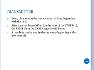
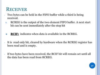
2.
-
Framing error:
occurs when the receiver does not detect the STOP bit at the expected
time. This happens because the receiver and the transmitter operates on
different baud rates.
-
When this happens, the FERR bit [RCSTA<2>] will be set, indicating
that the last received data has an error.
-
A framing error (bit set) does not prevent reception of new data.
-
The FERR bit is cleared by reading received data, so check must be done
before reading the received byte.
-
The FERR bit cannot be cleared by software. If needed, it can be cleared
by clearing the SPEN bit of the RCSTA register. It will simultaneously
cause reset of the whole USART system.
39](https://image.slidesharecdn.com/usart-131206180029-phpapp01/85/USART-39-320.jpg)
![SUMMARY
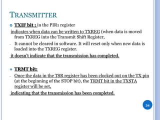
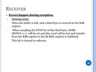
To make asynchronous connection using the PIC’s USART:
At the Transmitter end:
1.
Determine the value of the SPBRG register and the BRGH-bit
according to the required baud rate.
2.
The SYNC-bit [TXSTA<4>] is cleared, SPEN-bit [RCSTA<7>] is
set to enable the serial port.
3.
On 9-bit data transmission, the TX9-bit [TXSTA<6>] is set.
4.
TXEN-bit [TXSTA<5>] is set to enable data transmission.
5.
On 9-bit data transmission, value of the ninth bit should be
written to the TX9D-bit [TXSTA<0>].
6.
Transmission can be started again by writing 8-bit data to the
TXREG register, usually wait for at least (1ms) between every two
writes.
45](https://image.slidesharecdn.com/usart-131206180029-phpapp01/85/USART-45-320.jpg)
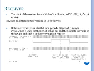
![SUMMARY
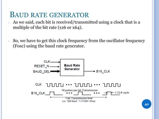
At the Receiver end:
1.
Determine the value of the SPBRG register and the BRGH-bit
according to the required baud rate.
2.
The SYNC-bit [TXSTA<4>] is cleared, SPEN-bit [RCSTA<7>] is
set to enable the serial port.
3.
On 9-bit data receive, the RX9-bit [RCSTA<6>] is set.
4.
Data receive should be enabled by setting the CREN-bit
[RCSTA<4>].
5.
The RCSTA register should be read to get information on possible
errors which have occurred during transmission.
6.
On 9-bit data receive, the ninth bit will be stored in RX9D-bit
[RCSTA<0>].
7.
Received 8-bit data stored in the RCREG register should be read.
46](https://image.slidesharecdn.com/usart-131206180029-phpapp01/85/USART-46-320.jpg)

1. To make asynchronous serial communication using a microcontroller's USART, the transmitter must configure the baud rate generator and enable transmission by writing data to the transmit register, while the receiver must configure the baud rate generator and enable reception to read incoming data from the receive register. 2. Key steps include setting the SPBRG register and BRGH bit to determine the baud rate, enabling the serial port and transmission/reception, handling 9-bit data if needed, and checking status registers for transmission completion or errors. 3. Asynchronous serial communication allows microcontrollers to transmit data bit by bit over a single line using start and stop bits for synchronization instead of a separate clock line.


![5G Explained! A High Level Overview [Introduction]](https://cdn.slidesharecdn.com/ss_thumbnails/5gexplainedahighleveloverview-260119165306-cc137a3e-thumbnail.jpg?width=640&height=640&fit=bounds)


