Downloaded 2,176 times
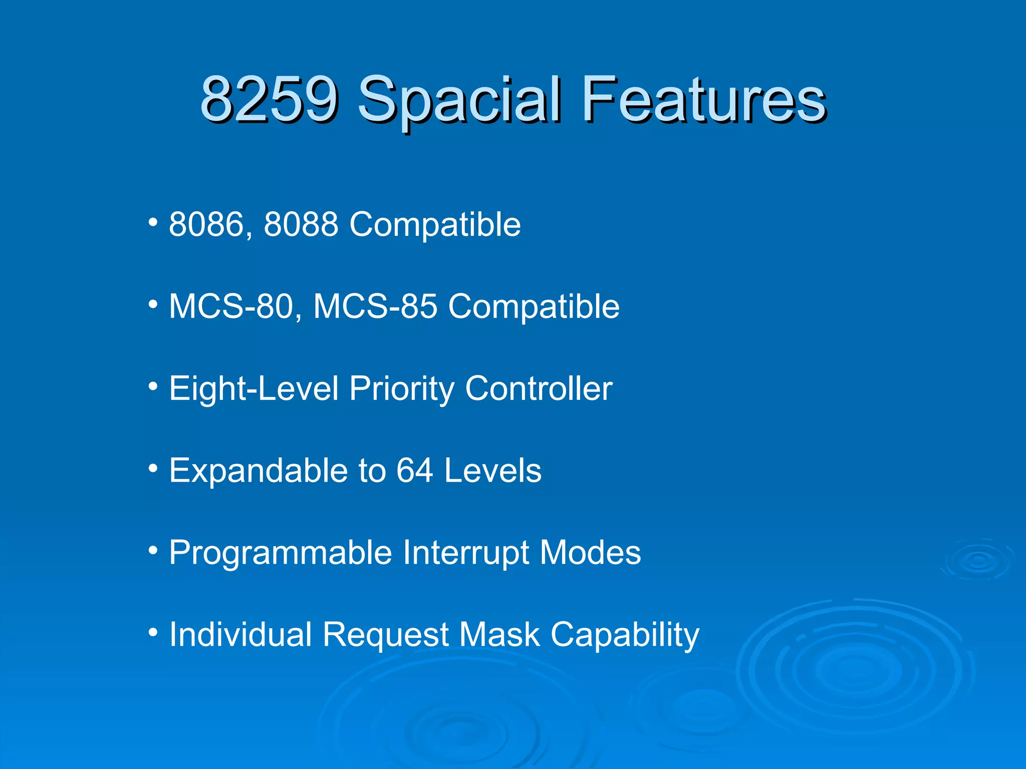
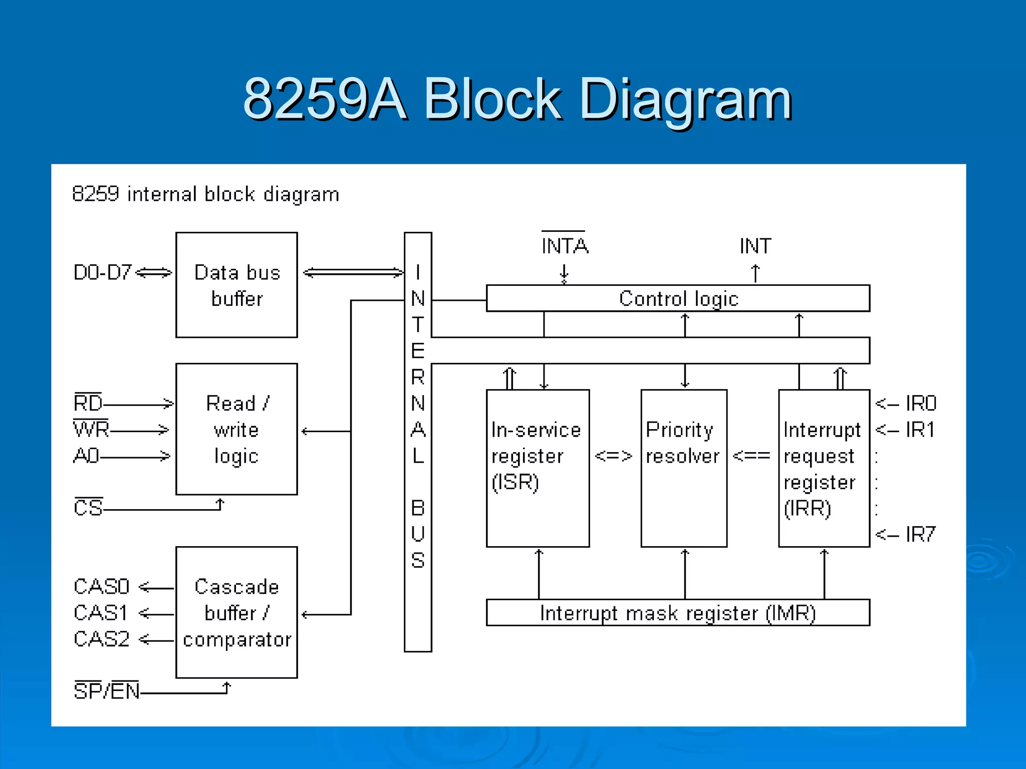
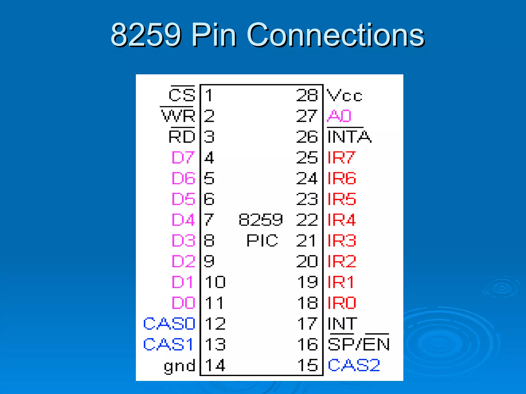


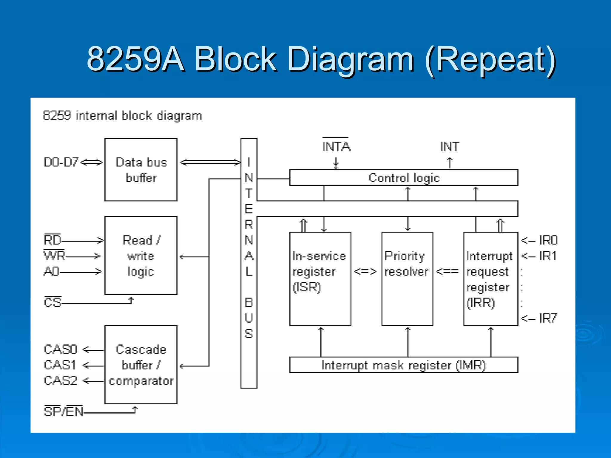

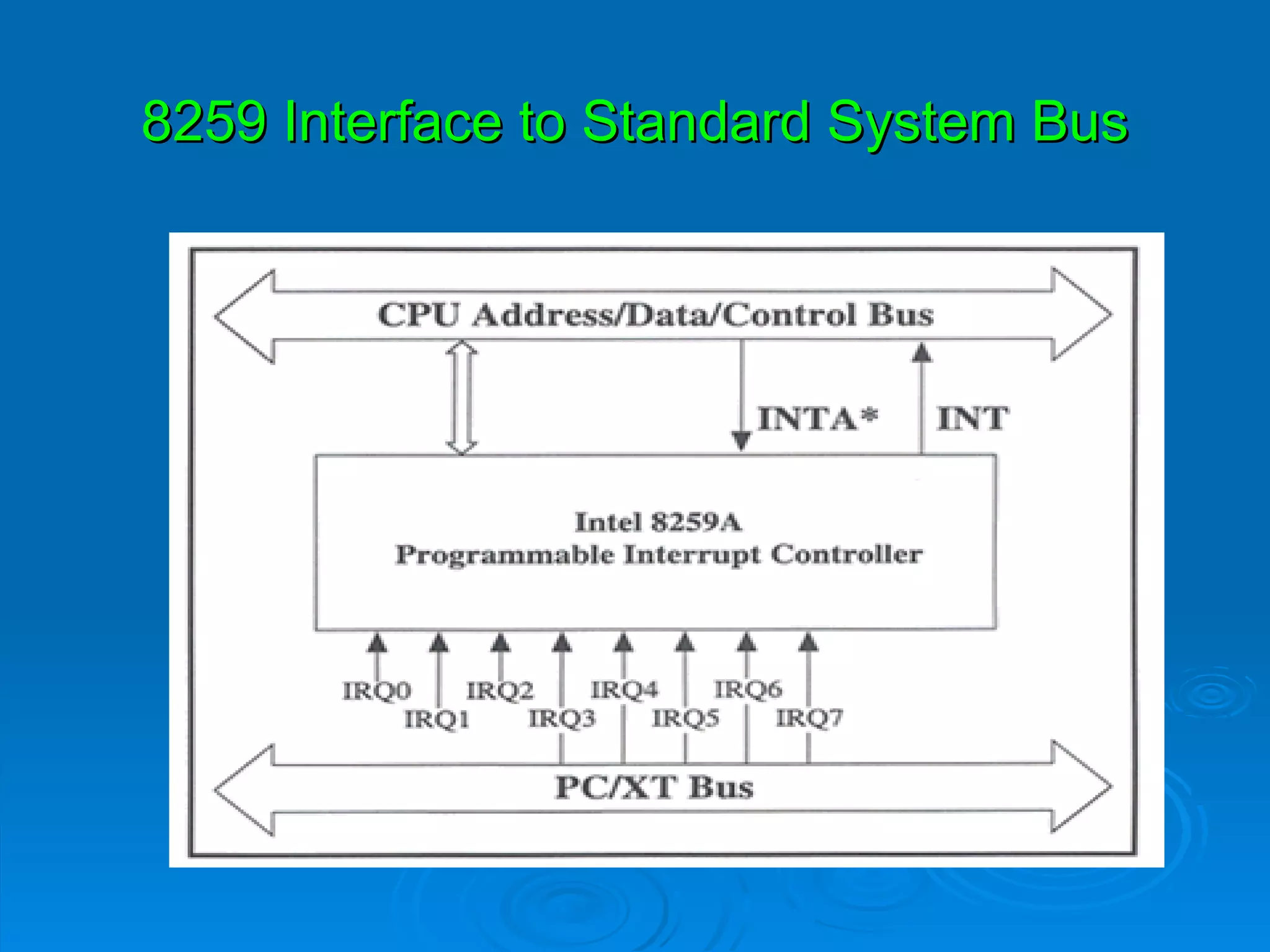
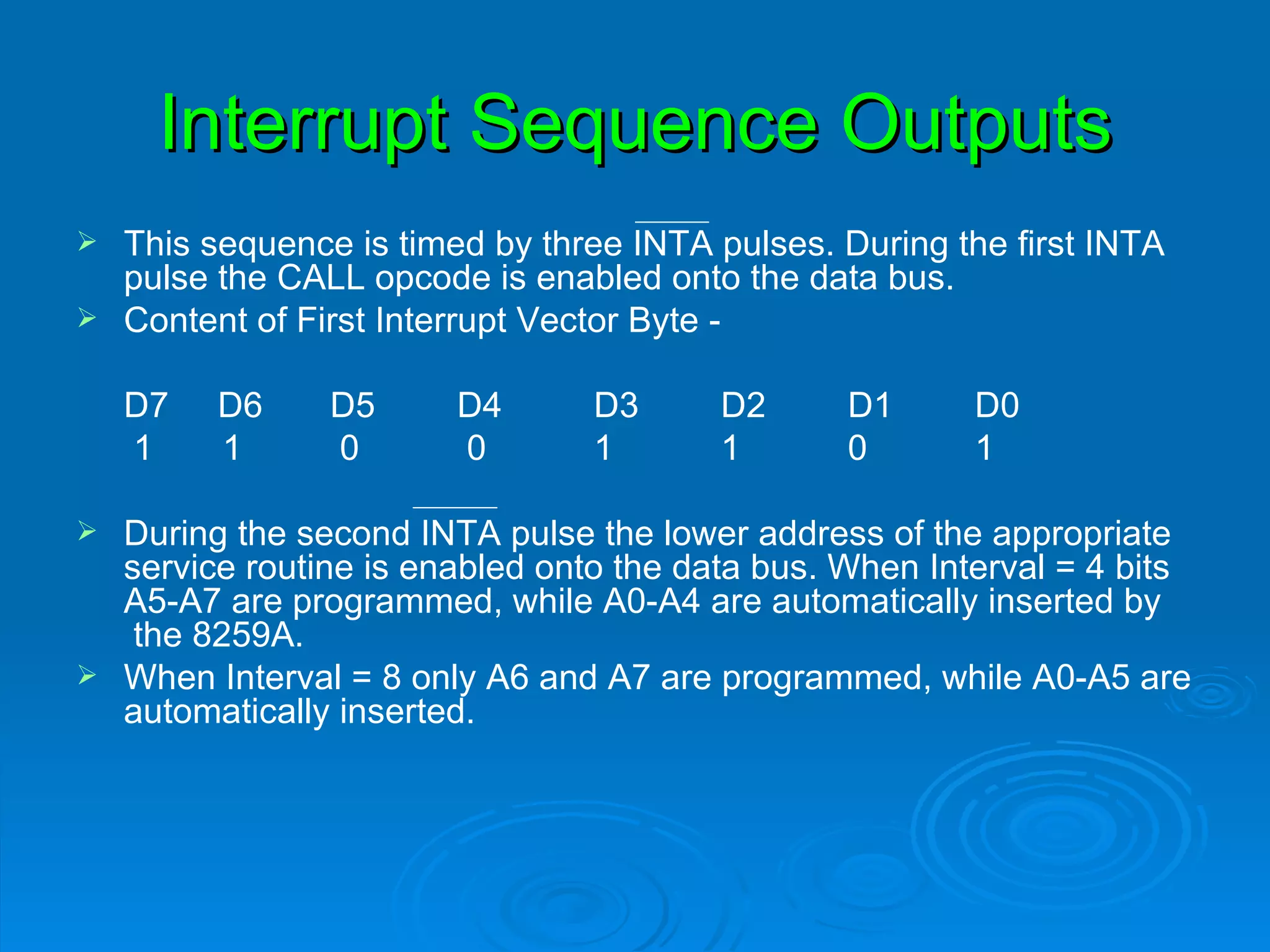

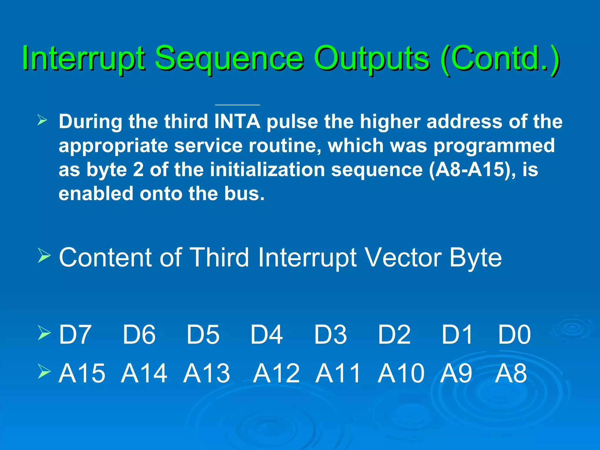
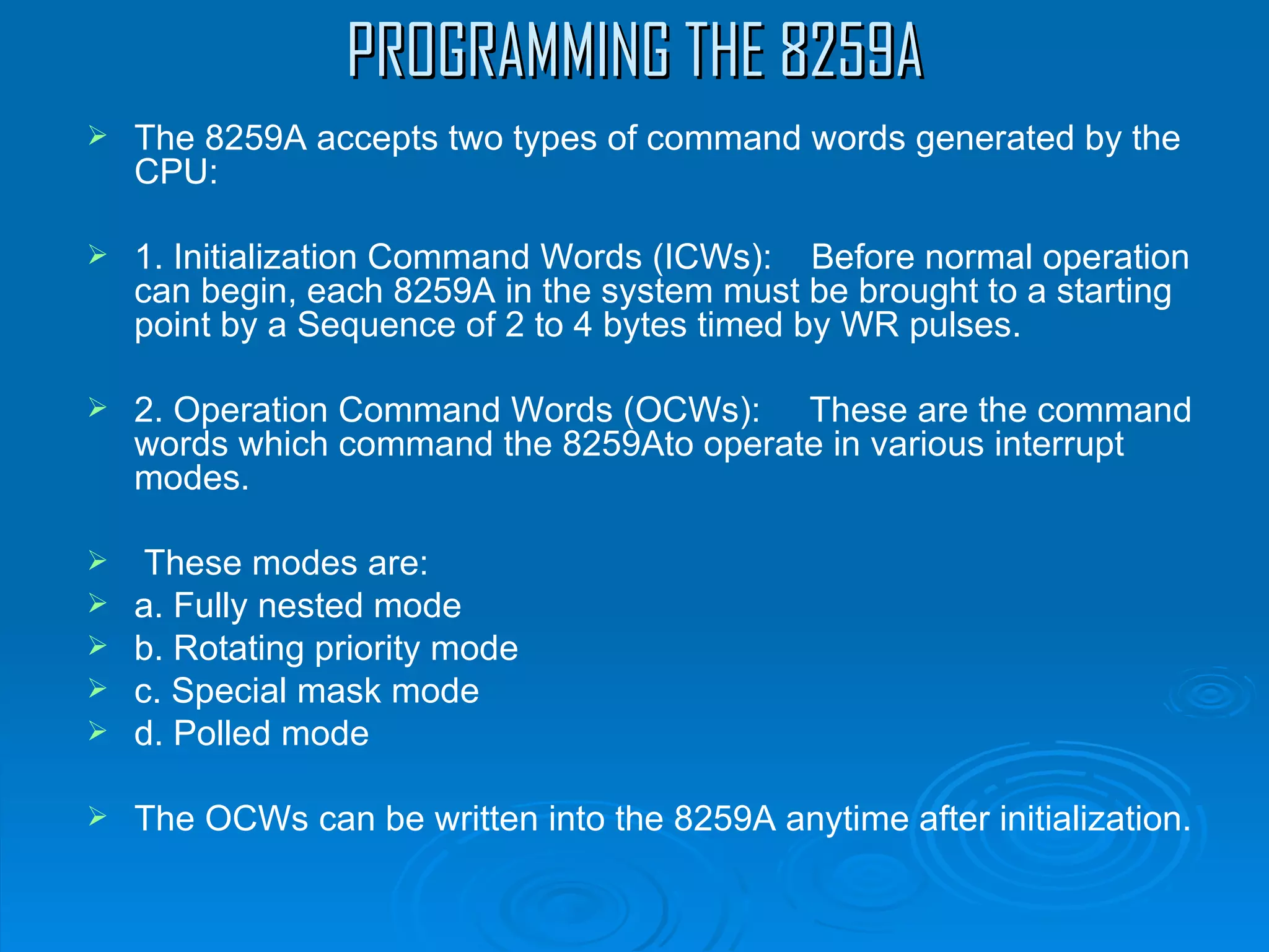
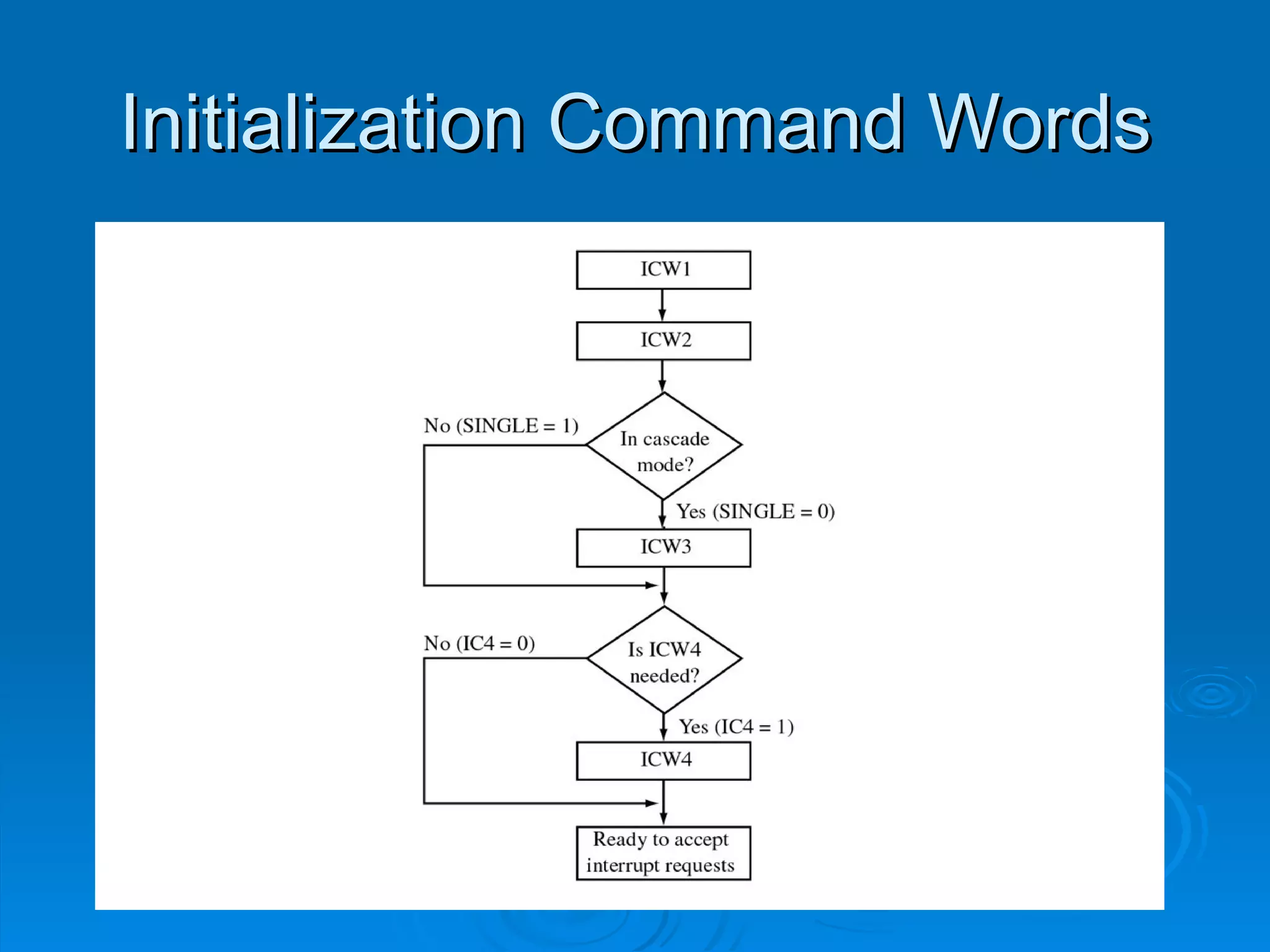
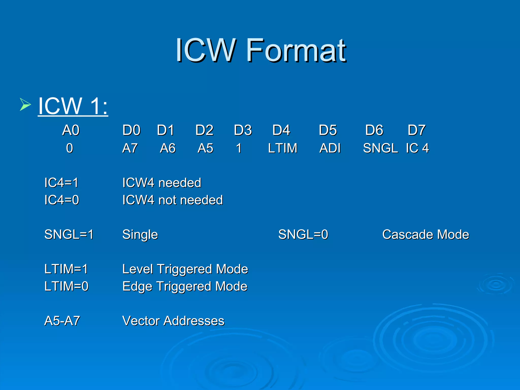
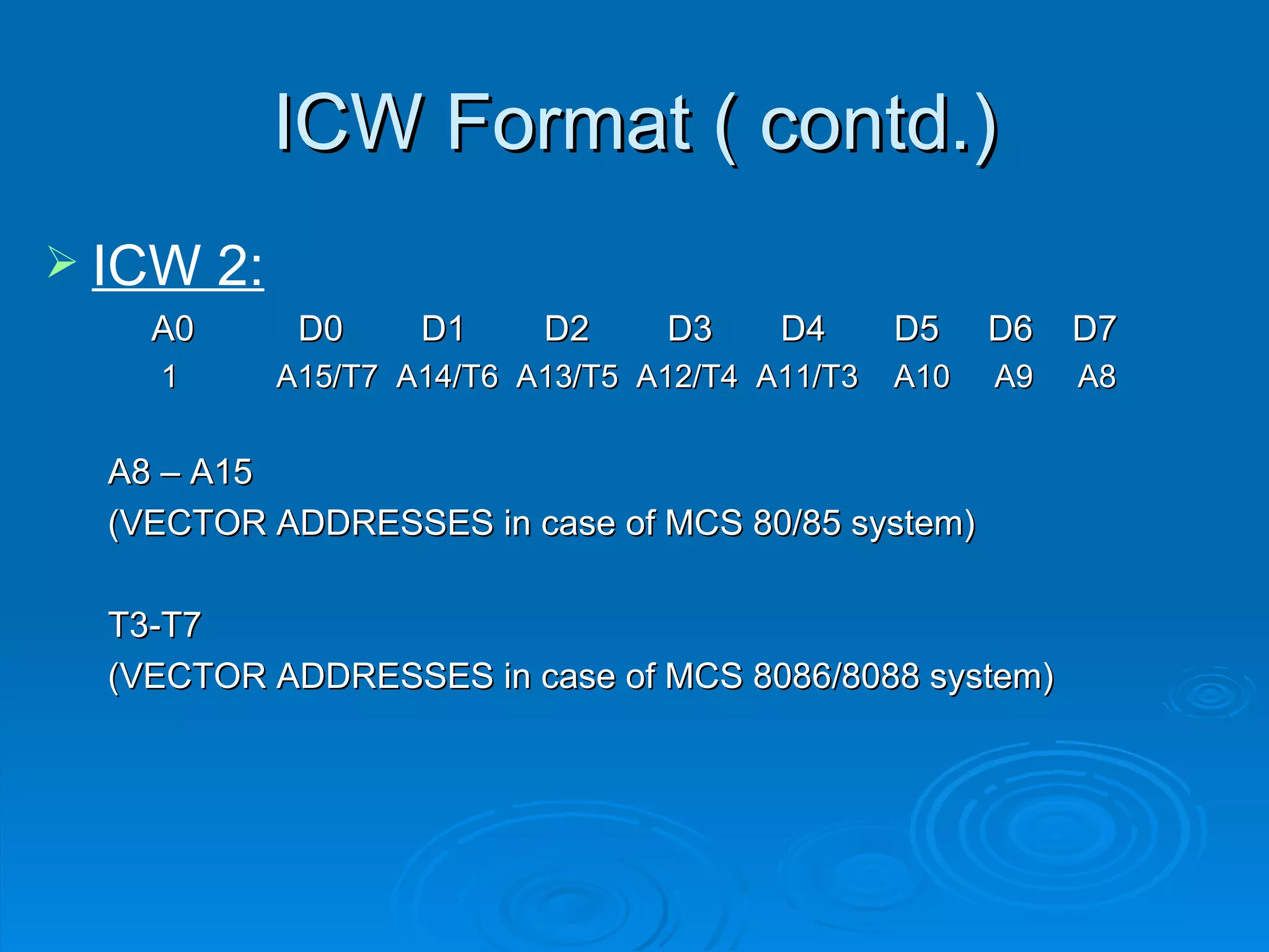

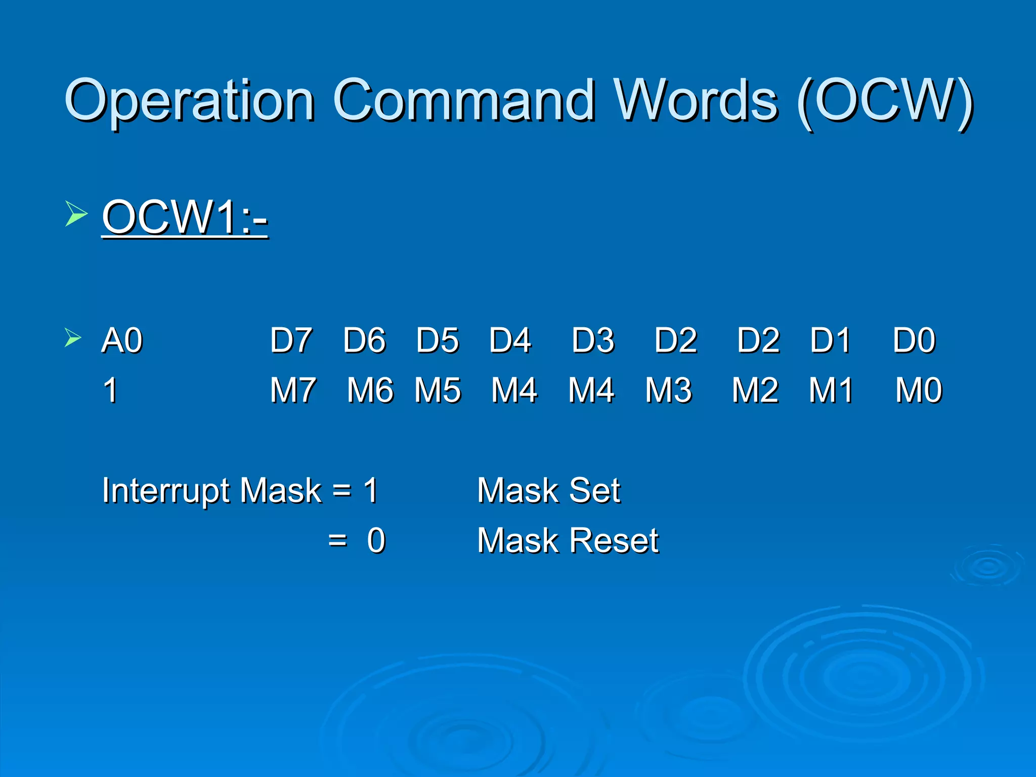
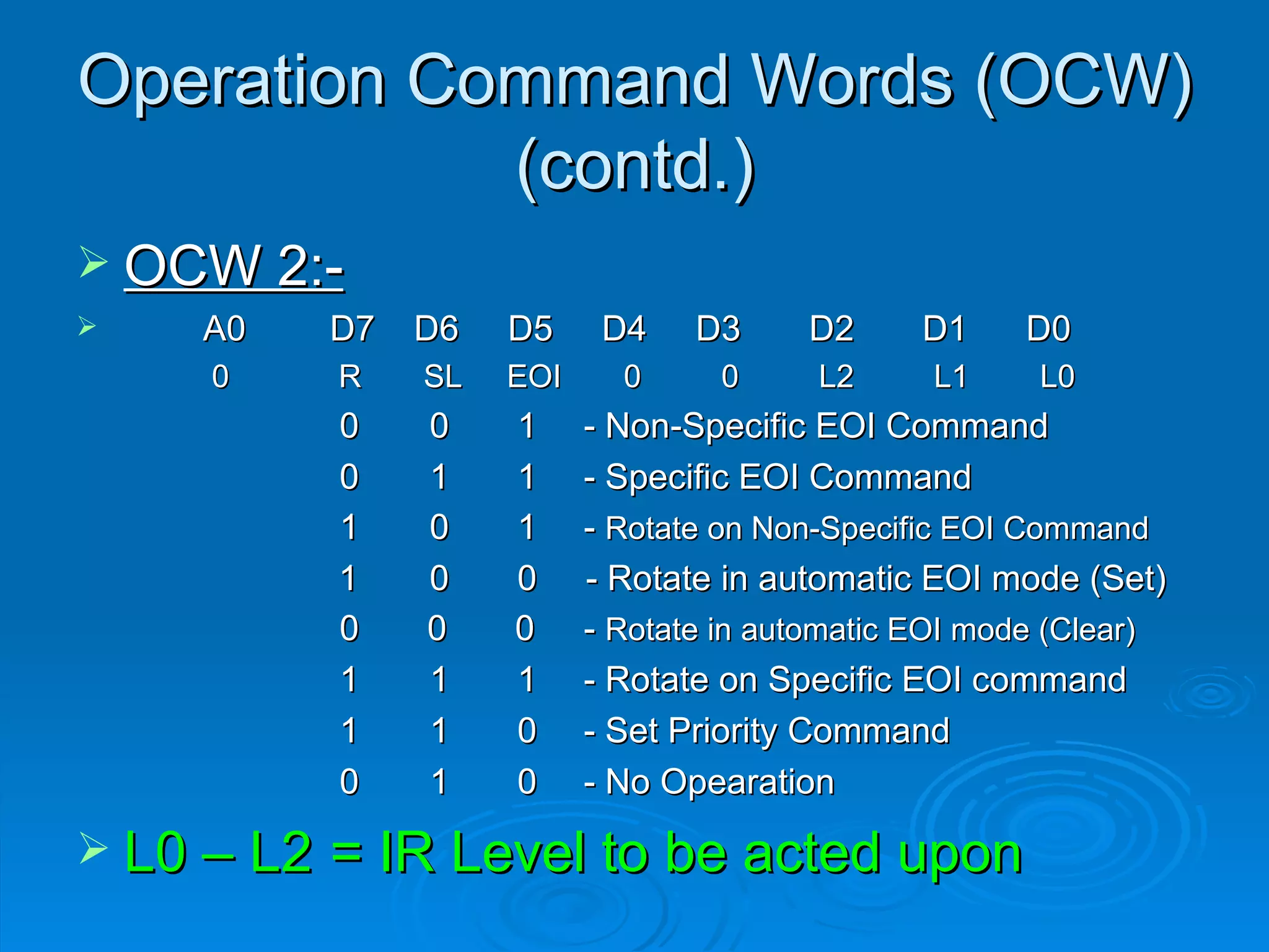

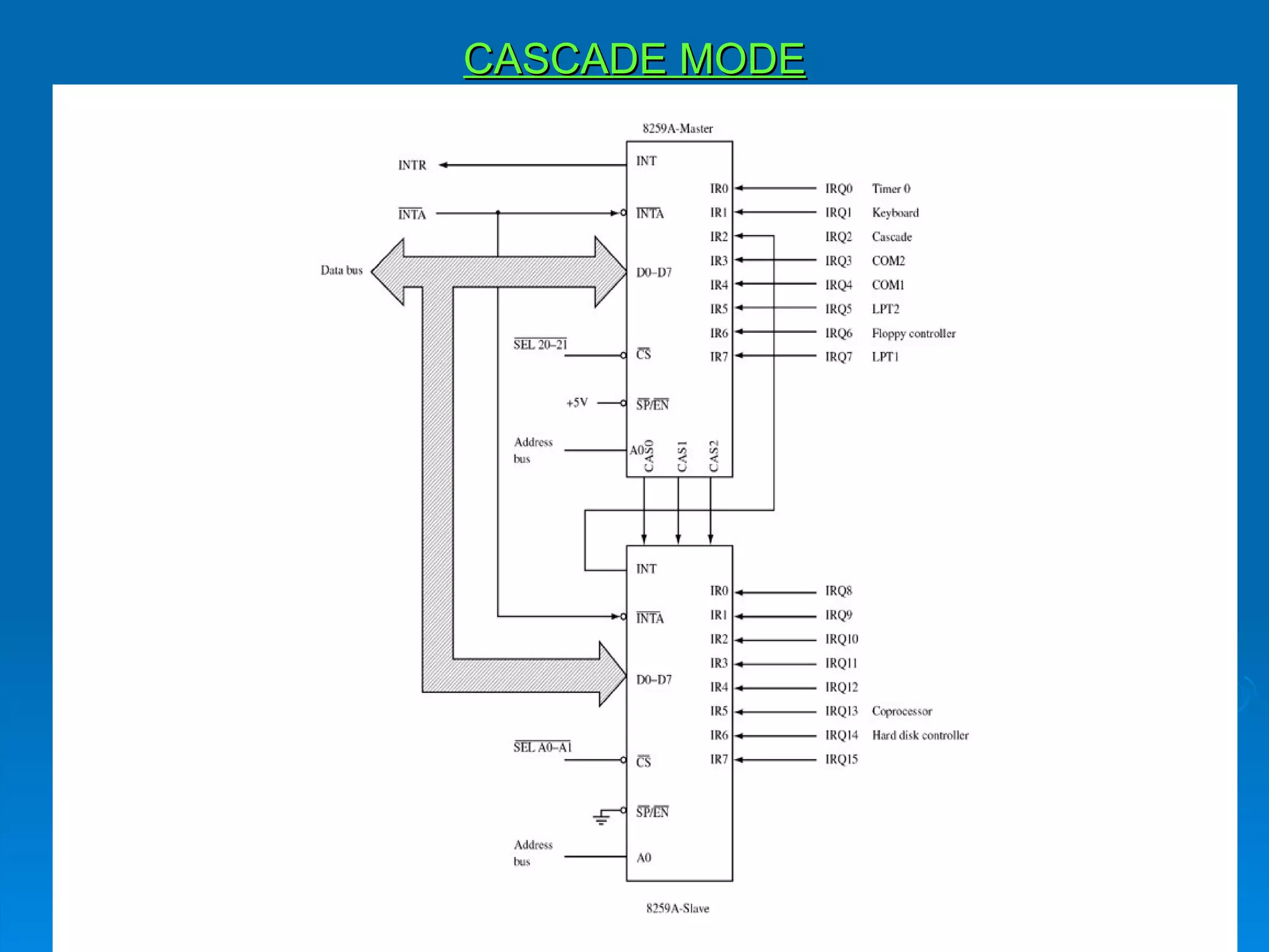


The document describes the 8259 programmable interrupt controller. It has 8 interrupt request lines that can be expanded to 64. It determines the priority of incoming interrupts and issues an interrupt signal to the CPU. Upon receiving an interrupt acknowledgement from the CPU, it provides vectoring data through 3 INTA pulses to direct the CPU to the appropriate interrupt service routine. It is programmed using initialization command words and operation command words to set interrupt priorities, masks, and modes.