This document discusses serial communication, including:
1) The advantages of serial communication over parallel communication for long distance communication due to lower wiring costs.
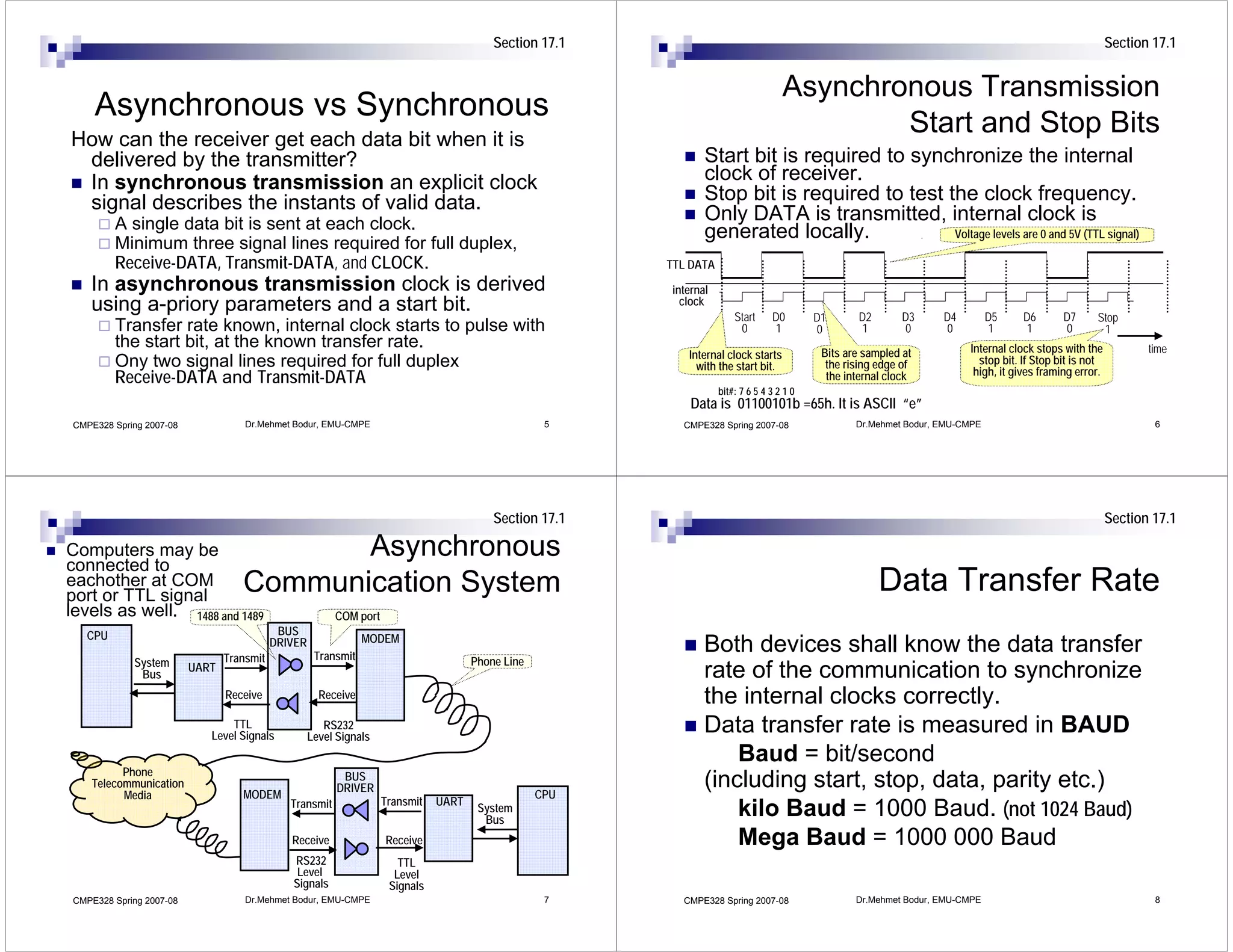
2) The differences between synchronous and asynchronous communication and between simplex, half duplex, and full duplex modes.
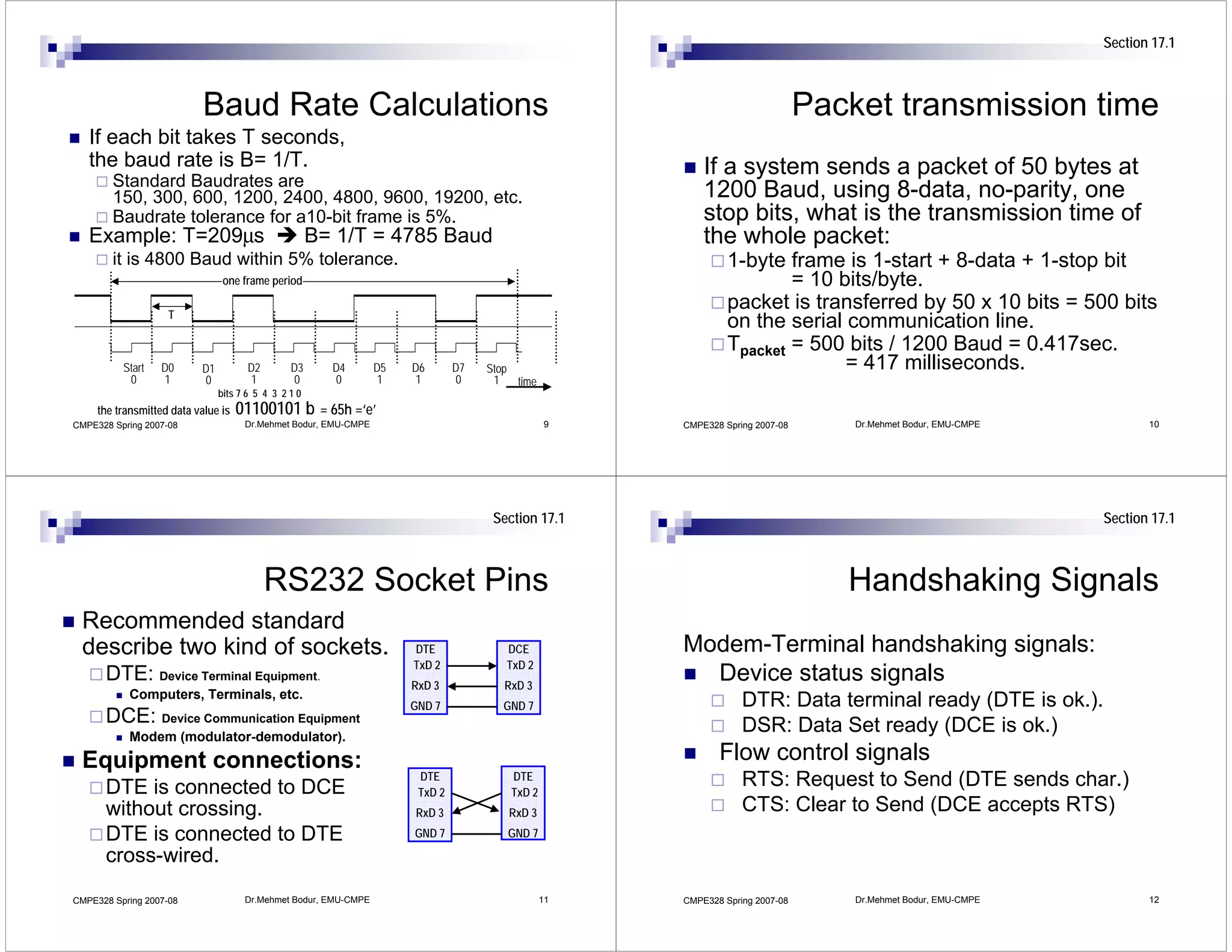
3) How start and stop bits are used to frame data for asynchronous serial communication and how baud rate and bits per second are measured.

![Section 17.4 Section 17.4
UART 8251 8251 UART Device
Register addressing
8251 USART
A processor may transmit/receive data in ~CS C/~D=00 (data) TXRDY
serial format without any extra hardware. writes to the transmit buffer D[0..7] TXE
~TXC
But it costs to the processing time of the reads from the receive buffer TXD
RXD
processor.
~CS C/~D=01 (control) RESET
RXRDY
A UART (Universal Asynchronous Receiver Transmitter) is writes to the CLK
~RXC
SY/BR
a hardware device that shifts out data bits mode register right after a reset. C/~D
DSR
to transmit a data byte, and also shifts-in command register after mode is ~RD
~DTR
~WR ~CTS
data bits to receive a data byte. written. ~CS ~RTS
reads from the status register.
CMPE328 Spring 2007-08 Dr.Mehmet Bodur, EMU-CMPE 13 CMPE328 Spring 2007-08 Dr.Mehmet Bodur, EMU-CMPE 14
Section 17.4 Section 17.4
8251 system bus connection 8251 Clock Signals
8251 USART CLK is system clock input
TXRDY 8251 USART
Data buffer D[0..7] D[0..7] TXE Transmit TXC and RXC are transmit-receive TXRDY
Clock
address is 308h ~TXC
TXD serial
clock inputs. D[0..7] TXE
~TXC
data There are three baudrate factors
Control/Status RXD TXD
RXD
RXRDY Receive divide by 1, 16 and 64.
address is 309h, RESET RESET ~RXC Clock
Example. Find RXC oscillator frequency RXRDY
CLK CLK RESET ~RXC
TXRDY and A0 C/~D
SY/BR Clock
Generator
for 1200 Baud operation with baudrate CLK
SY/BR
DSR factor 1/64. C/~D
RXRDY are for ~IOR ~RD
~DTR modem DSR
~IOW ~WR Solution: fRXC =1200*64 Hz = 76.8 kHz. ~RD
interrupted Address ~CS
~CTS
~RTS
handshaking
Example: What shall be the baudrate ~WR
~DTR
~CTS
Decoder ~308h – ~309h
operation. factor for 4800 Baud operation if RXC is ~CS ~RTS
connected to 19.2 kHz ?
Solution: 19.2kHz/4.8kHz = 4, 1/4
CMPE328 Spring 2007-08 Dr.Mehmet Bodur, EMU-CMPE 15 CMPE328 Spring 2007-08 Dr.Mehmet Bodur, EMU-CMPE 16](https://image.slidesharecdn.com/11serial0515-090920123651-phpapp02/75/11-Serial-0515-4-2048.jpg)


![[BDD 2025 - Full-Stack Development] Digital Accessibility: Why Developers nee...](https://cdn.slidesharecdn.com/ss_thumbnails/fs-digitalaccessibilitywhydevelopersneedtoknowandcarein2025-251127011019-0674441d-thumbnail.jpg?width=640&height=640&fit=bounds)


![[BDD 2025 - Full-Stack Development] Agentic AI Architecture: Redefining Syste...](https://cdn.slidesharecdn.com/ss_thumbnails/fs-agenticaiarchitectureredefiningsystemcommunication-251124030838-e6c70cc2-thumbnail.jpg?width=640&height=640&fit=bounds)


![[BDD 2025 - Mobile Development] Exploring Apple’s On-Device FoundationModels](https://cdn.slidesharecdn.com/ss_thumbnails/md-exploringappleson-devicefoundationmodels-251124030840-d690542c-thumbnail.jpg?width=640&height=640&fit=bounds)
![[BDD 2025 - Artificial Intelligence] Building AI Systems That Users (and Comp...](https://cdn.slidesharecdn.com/ss_thumbnails/ai-buildingaisystemsthatusersandcompanieslove-251124030845-038f7732-thumbnail.jpg?width=640&height=640&fit=bounds)


