Download as PDF, PPTX

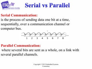
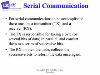
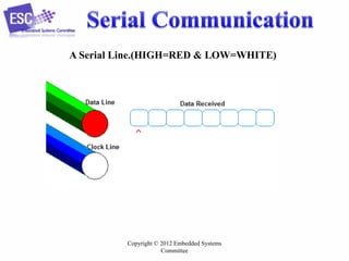
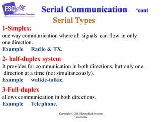
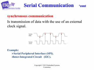
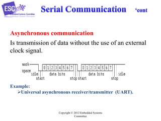


Serial communication involves transmitting data one bit at a time over a communication channel. It requires fewer cables than parallel communication and has lower costs. Serial communication uses a transmitter to convert data to a serial bit stream and a receiver to reassemble the data. Common serial interfaces for embedded systems include UART, SPI, and I2C. These interfaces are used to connect microcontrollers to devices like sensors, displays and memory.