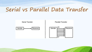
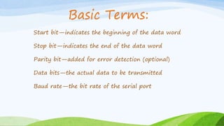
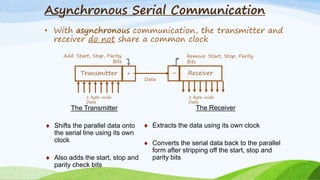
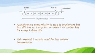
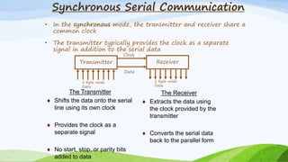
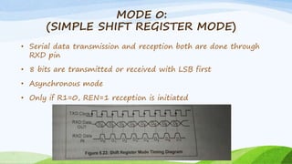
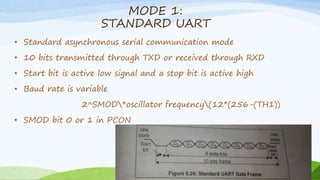
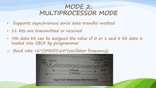
Serial Data
Transfer
8051
Serial vs Parallel Data Transfer
SERIAL COMMUNICATION(TELEPHONE LINE):
• long distance
• cheaper
• one bit/data line
PARALLEL COMMUNICATION (PRINTER):
• fast
• distance cannot be greater
• expensive
SERIAL COMMUNICATION
PISO SHIFT REGISTER
SIPO SHIFT REGISTER
DA CONVERTER
AD CONVERTER
Start bit—indicates the beginning of the data word
Stop bit—indicates the end of the data word
Parity bit—added for error detection (optional)
Data bits—the actual data to be transmitted
Baud rate—the bit rate of the serial port
Basic Terms:
Asynchronous Serial Communication
• With asynchronous communication, the transmitter and
receiver do not share a common clock
Transmitter Receiver+
1 byte-wide
Data
Data
–
1 byte-wide
Data
The Receiver
 Extracts the data using its own clock
 Converts the serial data back to the parallel
form after stripping off the start, stop and
parity bits
The Transmitter
 Shifts the parallel data onto
the serial line using its own
clock
 Also adds the start, stop and
parity check bits
Add: Start, Stop, Parity
Bits
Remove: Start, Stop, Parity
Bits
• Asynchronous transmission is easy to implement but
less efficient as it requires an extra 2-3 control bits
for every 8 data bits
• This method is usually used for low volume
transmission
D0 D1 D2 D3 D4 D5 D6 D7
Start Bit 1 or 2 Stop BitsParity Bit
1 Asynchronous Byte
Synchronous Serial Communication
• In the synchronous mode, the transmitter and receiver share a
common clock
• The transmitter typically provides the clock as a separate
signal in addition to the serial data
Transmitter Receiver
Data
Clock
The Receiver
 Extracts the data using
the clock provided by the
transmitter
 Converts the serial data
back to the parallel form
The Transmitter
 Shifts the data onto the serial
line using its own clock
 Provides the clock as a
separate signal
 No start, stop, or parity bits
added to data
1 byte-wide
Data
1 byte-wide
Data
9 Pin Connector on a DTE device (PC connection)
Male RS232 DB9
Pin Number Direction of signal:
1 Carrier Detect (CD) (from DCE) Incoming signal from a modem
2 Received Data (RD) Incoming Data from a DCE
3 Transmitted Data (TD) Outgoing Data to a DCE
4 Data Terminal Ready (DTR) Outgoing handshaking signal
5 Signal Ground Common reference voltage
6 Data Set Ready (DSR) Incoming handshaking signal
7 Request To Send (RTS) Outgoing flow control signal
8 Clear To Send (CTS) Incoming flow control signal
9 Ring Indicator (RI) (from DCE) Incoming signal from a modem
TXD(P3.1)
RXD(P3.0)
RXD
TXD
COM port of PC or device8051
How to Access UART?
• Each UART is accessed by two SFRs—SBUF and SCON
• The Serial Port Buffer (SBUF) is essentially two buffers:
writing loads data to be transmitted to the buffer and
reading accesses received data from the buffer.
• These are two separate and distinct buffers (registers): the
transmit write-only buffer and the receive read-only register
• The Serial Port Control register (SCON) contains
status and control bits
• The control bits set the operating mode for the
serial port, and status bits indicate the end of the
character transmission or reception
SCON Register:
OPERATING MODES OF SERIAL PORTS
• SERIAL PORT INTERFACE OF 8051 CAN
BE OPERATED UNDER FOUR MODES:
MODE 0
MODE 1
MODE 2
MODE 3
MODE 0:
(SIMPLE SHIFT REGISTER MODE)
• Serial data transmission and reception both are done through
RXD pin
• 8 bits are transmitted or received with LSB first
• Asynchronous mode
• Only if R1=0, REN=1 reception is initiated
MODE 1:
STANDARD UART
• Standard asynchronous serial communication mode
• 10 bits transmitted through TXD or received through RXD
• Start bit is active low signal and a stop bit is active high
• Baud rate is variable
2^SMOD*oscillator frequency(12*(256-(TH1))
• SMOD bit 0 or 1 in PCON
MODE 2:
MULTIPROCESSOR MODE
• Supports asynchronous serial data transfer method
• 11 bits are transmitted or received
• 9th data bit can be assigned the value of 0 or 1 and 8 bit data is
loaded into SBUF by programmer
o Baud rate =2^(SMOD)64*(oscillator frequency)
MODE 3
• It is same as mode 2 in all aspects except the baud rate
• Baud rate is variable here
• Calculation of BR is similar to the mode 1 using timer 1
• 11 bits are transmitted or received here
• 11 bits consists of a start bit (0), 8 data bits (LSB first), a
programmable 9th bit and a stop bit (1)
Serial data transfer

Serial data transfer

  • 1.
  • 2.
    Serial vs ParallelData Transfer
  • 3.
    SERIAL COMMUNICATION(TELEPHONE LINE): •long distance • cheaper • one bit/data line PARALLEL COMMUNICATION (PRINTER): • fast • distance cannot be greater • expensive
  • 4.
    SERIAL COMMUNICATION PISO SHIFTREGISTER SIPO SHIFT REGISTER DA CONVERTER AD CONVERTER
  • 5.
    Start bit—indicates thebeginning of the data word Stop bit—indicates the end of the data word Parity bit—added for error detection (optional) Data bits—the actual data to be transmitted Baud rate—the bit rate of the serial port Basic Terms:
  • 6.
    Asynchronous Serial Communication •With asynchronous communication, the transmitter and receiver do not share a common clock Transmitter Receiver+ 1 byte-wide Data Data – 1 byte-wide Data The Receiver  Extracts the data using its own clock  Converts the serial data back to the parallel form after stripping off the start, stop and parity bits The Transmitter  Shifts the parallel data onto the serial line using its own clock  Also adds the start, stop and parity check bits Add: Start, Stop, Parity Bits Remove: Start, Stop, Parity Bits
  • 7.
    • Asynchronous transmissionis easy to implement but less efficient as it requires an extra 2-3 control bits for every 8 data bits • This method is usually used for low volume transmission D0 D1 D2 D3 D4 D5 D6 D7 Start Bit 1 or 2 Stop BitsParity Bit 1 Asynchronous Byte
  • 8.
    Synchronous Serial Communication •In the synchronous mode, the transmitter and receiver share a common clock • The transmitter typically provides the clock as a separate signal in addition to the serial data Transmitter Receiver Data Clock The Receiver  Extracts the data using the clock provided by the transmitter  Converts the serial data back to the parallel form The Transmitter  Shifts the data onto the serial line using its own clock  Provides the clock as a separate signal  No start, stop, or parity bits added to data 1 byte-wide Data 1 byte-wide Data
  • 13.
    9 Pin Connectoron a DTE device (PC connection) Male RS232 DB9 Pin Number Direction of signal: 1 Carrier Detect (CD) (from DCE) Incoming signal from a modem 2 Received Data (RD) Incoming Data from a DCE 3 Transmitted Data (TD) Outgoing Data to a DCE 4 Data Terminal Ready (DTR) Outgoing handshaking signal 5 Signal Ground Common reference voltage 6 Data Set Ready (DSR) Incoming handshaking signal 7 Request To Send (RTS) Outgoing flow control signal 8 Clear To Send (CTS) Incoming flow control signal 9 Ring Indicator (RI) (from DCE) Incoming signal from a modem
  • 14.
  • 16.
    How to AccessUART? • Each UART is accessed by two SFRs—SBUF and SCON • The Serial Port Buffer (SBUF) is essentially two buffers: writing loads data to be transmitted to the buffer and reading accesses received data from the buffer. • These are two separate and distinct buffers (registers): the transmit write-only buffer and the receive read-only register
  • 19.
    • The SerialPort Control register (SCON) contains status and control bits • The control bits set the operating mode for the serial port, and status bits indicate the end of the character transmission or reception SCON Register:
  • 21.
    OPERATING MODES OFSERIAL PORTS • SERIAL PORT INTERFACE OF 8051 CAN BE OPERATED UNDER FOUR MODES: MODE 0 MODE 1 MODE 2 MODE 3
  • 22.
    MODE 0: (SIMPLE SHIFTREGISTER MODE) • Serial data transmission and reception both are done through RXD pin • 8 bits are transmitted or received with LSB first • Asynchronous mode • Only if R1=0, REN=1 reception is initiated
  • 23.
    MODE 1: STANDARD UART •Standard asynchronous serial communication mode • 10 bits transmitted through TXD or received through RXD • Start bit is active low signal and a stop bit is active high • Baud rate is variable 2^SMOD*oscillator frequency(12*(256-(TH1)) • SMOD bit 0 or 1 in PCON
  • 24.
    MODE 2: MULTIPROCESSOR MODE •Supports asynchronous serial data transfer method • 11 bits are transmitted or received • 9th data bit can be assigned the value of 0 or 1 and 8 bit data is loaded into SBUF by programmer o Baud rate =2^(SMOD)64*(oscillator frequency)
  • 25.
    MODE 3 • Itis same as mode 2 in all aspects except the baud rate • Baud rate is variable here • Calculation of BR is similar to the mode 1 using timer 1 • 11 bits are transmitted or received here • 11 bits consists of a start bit (0), 8 data bits (LSB first), a programmable 9th bit and a stop bit (1)