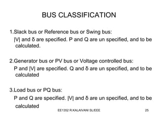
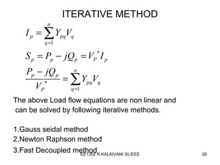
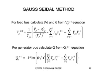
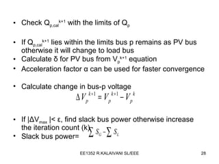
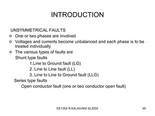
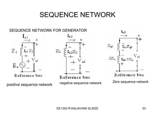
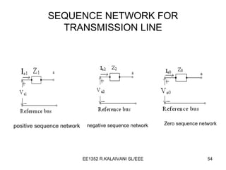
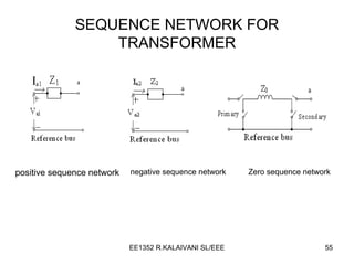
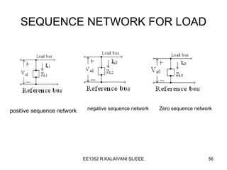
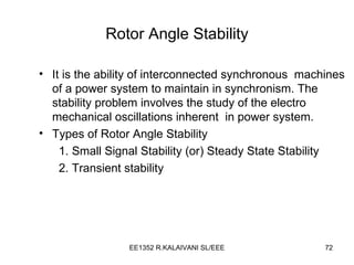
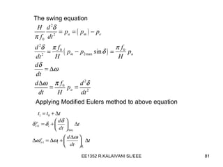
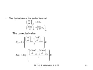
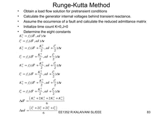
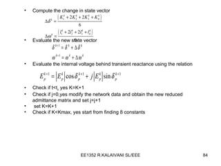
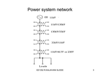
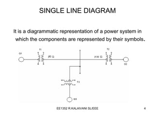
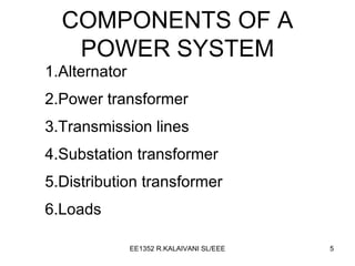
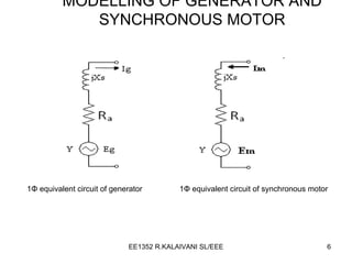
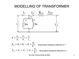
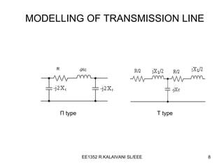
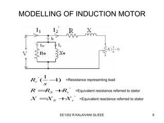
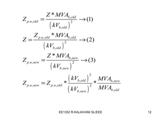
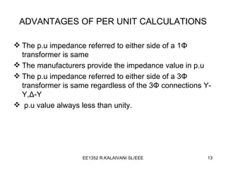
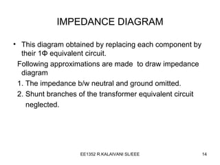
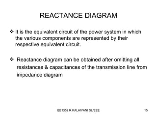
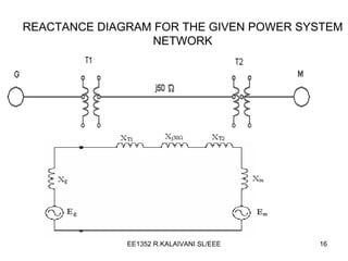
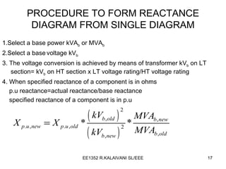
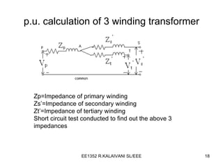
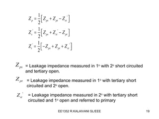
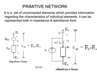
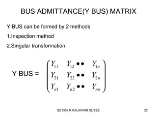
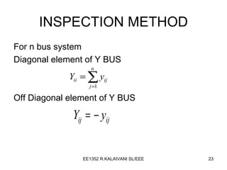
EE1352 POWER SYSTEM ANALYSIS R.KALAIVANI EEE DEPARTMENT RAJALAKSHMI ENGINEERING COLLEGE RAJALAKSHMI NAGAR,THANDALAM 602 105
UNIT I THE POWER SYSTEM- AN OVERVIEW  AND MODELLING
Power system network
SINGLE LINE DIAGRAM It is a diagrammatic representation of a power system in which the components are represented by their symbols .
COMPONENTS OF A POWER SYSTEM 1.Alternator 2.Power transformer 3.Transmission lines 4.Substation transformer 5.Distribution transformer 6.Loads
MODELLING OF GENERATOR AND SYNCHRONOUS MOTOR 1 Φ  equivalent circuit of generator 1 Φ  equivalent circuit of synchronous motor
MODELLING OF TRANSFORMER =Equivalent resistance referred to 1 o =Equivalent reactance referred to 1 o
MODELLING OF TRANSMISSION LINE Π   type T  type
MODELLING OF INDUCTION MOTOR =Resistance representing load =Equivalent resistance referred to stator =Equivalent reactance referred to stator
per unit=actual value/base value Let KVA b =Base KVA kV b =Base voltage Z b =Base impedance in  Ω
Changing the base of per unit quantities Let  z = actual impedance( Ω ) = base impedance   ( Ω ) Let   represent old base values represent new base values
 
ADVANTAGES OF PER UNIT CALCULATIONS The p.u impedance referred to either side of a 1 Φ  transformer is same The manufacturers provide the impedance value in p.u The p.u impedance referred to either side of a 3 Φ  transformer is same regardless of the  3 Φ  connections  Y-Y, Δ -Y p.u value always less than unity.
IMPEDANCE DIAGRAM This diagram obtained by replacing each component by their 1 Φ   equivalent circuit. Following app roximations are made  to draw impedance diagram 1. The impedance b/w neutral and ground omitted. 2. Shunt branches of the transformer equivalent circuit  neglected.
REACTANCE DIAGRAM It is the equivalent circuit of the power system in which the various components are represented by their respective equivalent circuit. Reactance diagram can be obtained after omitting all  resistances & capacitances of the transmission line from impedance diagram
REACTANCE DIAGRAM FOR THE GIVEN POWER SYSTEM NETWORK
PROCEDURE TO FORM REACTANCE DIAGRAM FROM SINGLE DIAGRAM 1.Select a base power kVA b  or MVA b   2.Select a base   voltage kV b 3. The voltage conversion is achieved by means of transformer kV b  on LT section= kV b  on HT section x LT voltage rating/HT voltage rating 4. When specified reactance of a component is in ohms p.u reactance=actual reactance/base reactance specified reactance of a component is in p.u
p.u. calculation of 3 winding transformer Zp=Impedance of primary winding Zs’=Impedance of secondary winding Zt’=Impedance of tertiary winding Short circuit test conducted to find out the above 3 impedances
= Leakage impedance measured in 1 o  with 2 o  short circuited and tertiary open.  = Leakage impedance measured in 1 o  with tertiary short circuited and 2 o  open.  = Leakage impedance measured in 2 o  with tertiary short circuited and 1 o  open and referred to primary
UNIT II POWER FLOW ANALYSIS
PRIMITIVE NETWORK   It is a  set of unconnected elements which provides information regarding the characteristics of individual elements. it can be represented both in impedance & admittance form
BUS ADMITTANCE(Y BUS) MATRIX Y BUS can be formed by 2 methods 1.Inspection method 2.Singular transformation Y BUS =
INSPECTION METHOD For n bus system Diagonal element of Y BUS Off Diagonal element of Y BUS
SINGULAR TRANSFORMATION METHOD Y BUS =  Where [y]=primitive admittance A=bus incidence matrix
BUS CLASSIFICATION 1.Slack bus or Reference bus or Swing bus: |V| and  δ  are specified. P and Q are un specified, and to be calculated. 2.Generator bus or PV bus or Voltage controlled bus: P and  |V|  are specified. Q and  δ  are un specified, and to be calculated  3.Load bus or PQ bus: P and Q   are specified.  |V|  and  δ  are un specified, and to be calculated
ITERATIVE METHOD The above Load flow equations are non linear and can be solved by following iterative methods. 1.Gauss seidal method 2.Newton Raphson method 3.Fast Decoupled method
GAUSS SEIDAL METHOD For load bus   calculate |V| and  δ  from V p k+1  equation   For generator bus calculate Q from Q P K+1  equation
Check Q p,cal k+1  with the limits of Q p If Q p,cal k+1  lies within the limits bus p remains as PV bus otherwise it will change to load bus Calculate  δ  for PV bus from  V p k+1  equation Acceleration factor  α  can be used for faster convergence Calculate change in bus-p voltage If | Δ V max  |<  ε , find slack bus power otherwise increase the iteration count (k) Slack bus power=
NEWTON RAPHSON METHOD
Calculate |V| and  δ  from the following equation If   stop the iteration otherwise increase the iteration count (k)
FAST DECOUPLED METHOD J 2  & J 3  of Jacobian matrix are zero
This method   requires more iterations than NR  method but less time per iteration It is useful for in contingency analysis
COMPARISION BETWEEN ITERATIVE METHODS Gauss – Seidal Method Computer memory requirement is less. Computation time per iteration is less. It requires less number of arithmetic operations to complete an iteration and ease in programming. No. of iterations are more for convergence and  rate of convergence is slow (linear convergence characteristic. No. of iterations increases with the increase of no. of buses.
NEWTON – RAPHSON METHOD Superior convergence because of quadratic convergence. It has an 1:8 iteration ratio compared to GS method. More accurate. Smaller no. of iterations and used for large size systems. It is faster and no. of iterations is independent of the no. of buses. Technique is difficult and calculations involved in each iteration are more and thus computation time per iteration is large. Computer memory requirement is large, as the elements of jacobian matrix are to be computed in each iteration. Programming logic is more complex.
FAST DECOUPLED METHOD It is simple and computationally efficient. Storage of jacobian matrix elements are60% of NR method computation time per iteration is less. Convergence is geometric,2 to 5 iterations required for accurate solutions Speed for iterations is 5 times that of NR method and 2-3 times of GS method
UNIT III FAULT ANALYSIS-BALANCED FAULT
Need for fault analysis To determine the magnitude of fault current throughout the power system after fault occurs. To select the ratings for fuses, breakers and switchgear. To check the MVA ratings of the existing circuit breakers when new generators are added into a system.
BALANCED THREE PHASE FAULT All the three phases are short circuited to each other and to earth. Voltages and currents of the system balanced after the symmetrical fault occurred. It is enough to consider any one phase for analysis. SHORT CIRCUIT CAPACITY It is the product of magnitudes of the prefault voltage and the post fault current. It is used to determine the dimension of a bus bar and the interrupting capacity of a circuit breaker.
Short Circuit Capacity (SCC)
Procedure for calculating short circuit capacity and fault current Draw a single line diagram and select common base S b  MVA and kV Draw the reactance diagram and calculate the total p.u impedance from the fault point to source (Thevenin impedance Z T ) Determine SCC and I f
ALGORITHM FOR SHORT CIRCUIT ANALYSIS USING BUS IMPEDANCE MATRIX Consider a n bus network. Assume that three phase fault  is applied at bus k through a fault impedance z f Prefault voltages at all the buses are Draw the Thevenin equivalent circuit i.e Zeroing all voltage sources and add voltage source  at faulted bus k and draw the reactance diagram
The change in bus voltage due to fault is The bus voltages during the fault is The current entering into all the buses is zero.the current entering into faulted bus k is –ve of the current leaving the bus k
 
ALGORITHM FOR FORMATION OF THE BUS IMPEDANCE MATRIX Modification of Zbus matrix involves any one of the following 4 cases Case 1:adding a branch impedance z b  from   a new bus p to  the reference bus Addition of new bus  will increase the order the Z bus  matrix by 1 (n+1)th column and row elements are zero except the diagonal diagonal element is z b
Case 2: adding a branch impedance z b  from   a new bus p to the existing bus q  Addition of new bus  will increase the order the Z bus  matrix by 1 The elements of (n+1)th column and row are the elements of  qth column and row and the diagonal element is Z qq +Z b Case 3:adding a branch impedance z b  from   an existing bus p to  the reference bus The elements of (n+1)th column and row are the elements of  qth column and row and the diagonal element is Z qq +Z b  and  (n+1)th row and column should be eliminated using the following formula
Case 4:adding a branch impedance z b  between existing buses h and q  elements of (n+1)th column are elements of bus h column – bus q column and elements of (n+1)th row are elements of  bus h row – bus q row  the diagonal element= and (n+1)th row and column should be eliminated using the following formula
UNIT IV FAULT ANALYSIS- SYMMETRICAL COMPONENTS AND UNBALANCED FAULT
INTRODUCTION UNSYMMETRICAL FAULTS One or two phases are involved Voltages and currents become unbalanced and each phase is to be treated individually The various types of faults are Shunt type faults 1.Line to Ground fault (LG) 2. Line to Line fault (LL) 3. Line to Line to Ground fault (LLG) Series type faults Open conductor fault (one or two conductor open fault)
FUNDAMENTALS OF SYMMETRICAL COMPONENTS Symmetrical components can be used to transform  three phase unbalanced voltages and currents to balanced voltages and currents Three phase unbalanced phasors can be resolved into following three sequences 1.Positive sequence components 2. Negative sequence components 3. Zero sequence components
Positive sequence components Three phasors with equal magnitudes, equally displaced from one another by 120 o  and phase sequence is same as that of original phasors.  Negative sequence components Three phasors with equal magnitudes, equally displaced from one another by 120 o  and phase sequence is opposite to that of original phasors. Zero sequence components Three phasors with equal magnitudes and displaced from one another by 0 o
RELATIONSHIP BETWEEN UNBALANCED VECTORS AND SYMMETRICAL COMPONENTS Similarly we can obtain for currents also
SEQUENCE IMPEDANCE Impedances offered by power system components to positive, negative and zero sequence currents. Positive sequence impedance The impedance of a component when positive sequence currents alone are flowing. Negative sequence impedance The impedance of a component when negative sequence currents alone are flowing. Zero sequence impedance The impedance of a component when zero sequence currents alone are flowing.
SEQUENCE NETWORK SEQUENCE NETWORK FOR GENERATOR positive sequence network negative sequence network Zero sequence network
SEQUENCE NETWORK FOR TRANSMISSION LINE positive sequence network negative sequence network Zero sequence network
SEQUENCE NETWORK FOR TRANSFORMER positive sequence network negative sequence network Zero sequence network
SEQUENCE NETWORK FOR LOAD positive sequence network negative sequence network Zero sequence network
SINGLE LINE TO GROUND FAULT Consider a fault between phase a and ground through an impedance z f
LINE TO LINE (LL) FAULT Consider a fault between phase b and c through an impedance z f
DOUBLE LINE TO GROUND (LLG) FAULT Consider a fault between phase b and c  through an impedance z f  to ground
UNBALANCED FAULT ANALYSIS USING BUS IMPEDANCE MATRIX SINGLE LINE TO GROUND FAULT USING Z bus Consider a fault between phase a and ground through an impedance z f  at bus k For a fault at bus k the symmetrical components of fault current
LINE TO LINE (LL) FAULT Consider a fault between phase b and c through an impedance z f
DOUBLE LINE TO GROUND (LLG) FAULT Consider a fault between phase b and c  through an impedance z f  to ground
BUS VOLTAGES AND LINE CURRENTS DURING FAULT
UNIT V POWER SYSTEM STABILITY
STABILITY The tendency of a power system to develop restoring forces equal to or greater than the disturbing forces to maintain the state of equilibrium. Ability to keep the machines in synchronism with another machine
CLASSIFICATION OF STABILITY Steady state stability Ability of the power system to regain synchronism after small and slow disturbances (like gradual power changes) Dynamic stability Ability of the power system to regain synchronism after small disturbances occurring for a long time (like changes in turbine speed, change in load) Transient stability This concern with sudden and large changes in the network conditions i.e. .  sudden changes in application or removal of loads, line switching operating  operations, line faults, or loss of excitation.
Steady state limit is the maximum power that can be transferred without the system become  unstable when the load in increased gradually under steady state conditions. Transient limit is the maximum power that can be transferred without the system becoming unstable when a sudden or large disturbance occurs.
Swing Equation for Single Machine Infinite Bus System The equation governing the motion of the rotor of a synchronous machine  where J=The total moment of inertia of the rotor(kg-m 2 ) =Singular displacement of the rotor T m =Mechanical torque (N-m) T e =Net electrical torque (N-m) T a =Net accelerating torque (N-m)
Where p m  is the shaft power input to the machine p e  is the electrical power  p a  is the accelerating power
δ  and  ω s  are in electrical radian p.u p.u H=machine inertia constant
Swing Equation for Multimachine System p.u =machine rating(base) =system base
Rotor Angle Stability It is the ability of interconnected synchronous  machines of a power system to maintain in synchronism. The stability problem involves the study of the electro mechanical oscillations inherent  in power system. Types of Rotor Angle Stability 1. Small Signal Stability (or) Steady State Stability 2. Transient stability
Voltage Stability It is the ability of a power system to maintain steady acceptable voltages at all buses in the system under normal operating conditions and after being subjected to a disturbance. The major factor for instability is the  inability of the power system to meet the demand for reactive power.
Mid Term Stability It represents transition between short term and long   term responses. Typical ranges of time periods. 1. Short term  : 0 to 10s 2. Mid Term  : 10 to few minutes   3. Long Term : a few minutes to 10’s of minutes Long Term Stability Usually these problem be associated with 1. Inadequacies in equipment responses. 2. Poor co-ordination of control and protection equipment. 3. Insufficient active/reactive power reserves.
Equal Area Criterion This is a simple graphical method to predict the transient stability of two machine system or a single machine against infinite bus. This criterion does not require swing equation or solution of swing equation to determine the stability condition. The stability conditions are determined by equating the areas of segments on power angle diagram.
Factors Affecting Transient Stability Strength of the transmission network within the system and of the tie lines to adjacent systems. The characteristics of generating units including inertia of rotating parts and electrical properties such as transient reactance and magnetic saturation characteristics of the stator and rotor. Speed with which the faulted lines or equipments can be disconnected.
Numerical Integration methods  Euler’s method Modified Euler’s method Runge-Kutta method
EULER’S METHOD It is equivalent of using   the first two terms of the Taylor series of expansion for ‘x’ around point (x 0, t 0 ) at x= x 0 Successive step   can be at x= x 2 at x=x 0  is the slope of the curve at (x 0, t 0 ) It is a first order method &slope is constant. It depends the propagation error
MODIFIED EULER’S METHOD Using first derivative of the initial point  next point is obtained the step Using this x 1 p  dx/dt at x 1 p =f(t 1,   x 1 p ) Corrected value is
Numerical Solution of the swing equation   Input power p m =constant At steady state p e =p m , At synchronous speed
The swing equation Applying Modified Eulers method to above equation
The derivatives at the end of interval The corrected value
Runge-Kutta Method Obtain a load flow solution for pretransient conditions Calculate the generator internal voltages behind transient reactance. Assume the occurrence of a fault and calculate the reduced admittance matrix Initialize time count K=0,J=0 Determine the eight constants
Compute the change in state vector Evaluate the new state vector Evaluate the internal voltage behind transient reactance using the relation Check if t<t c  yes K=K+1 Check if j=0,yes modify the network data and obtain the new reduced admittance matrix and set j=j+1 set K=K+1 Check if K<Kmax, yes start from finding 8 constants

Newton Raphson

  • 1.
    EE1352 POWER SYSTEMANALYSIS R.KALAIVANI EEE DEPARTMENT RAJALAKSHMI ENGINEERING COLLEGE RAJALAKSHMI NAGAR,THANDALAM 602 105
  • 2.
    UNIT I THEPOWER SYSTEM- AN OVERVIEW AND MODELLING
  • 3.
  • 4.
    SINGLE LINE DIAGRAMIt is a diagrammatic representation of a power system in which the components are represented by their symbols .
  • 5.
    COMPONENTS OF APOWER SYSTEM 1.Alternator 2.Power transformer 3.Transmission lines 4.Substation transformer 5.Distribution transformer 6.Loads
  • 6.
    MODELLING OF GENERATORAND SYNCHRONOUS MOTOR 1 Φ equivalent circuit of generator 1 Φ equivalent circuit of synchronous motor
  • 7.
    MODELLING OF TRANSFORMER=Equivalent resistance referred to 1 o =Equivalent reactance referred to 1 o
  • 8.
    MODELLING OF TRANSMISSIONLINE Π type T type
  • 9.
    MODELLING OF INDUCTIONMOTOR =Resistance representing load =Equivalent resistance referred to stator =Equivalent reactance referred to stator
  • 10.
    per unit=actual value/basevalue Let KVA b =Base KVA kV b =Base voltage Z b =Base impedance in Ω
  • 11.
    Changing the baseof per unit quantities Let z = actual impedance( Ω ) = base impedance ( Ω ) Let represent old base values represent new base values
  • 12.
  • 13.
    ADVANTAGES OF PERUNIT CALCULATIONS The p.u impedance referred to either side of a 1 Φ transformer is same The manufacturers provide the impedance value in p.u The p.u impedance referred to either side of a 3 Φ transformer is same regardless of the 3 Φ connections Y-Y, Δ -Y p.u value always less than unity.
  • 14.
    IMPEDANCE DIAGRAM Thisdiagram obtained by replacing each component by their 1 Φ equivalent circuit. Following app roximations are made to draw impedance diagram 1. The impedance b/w neutral and ground omitted. 2. Shunt branches of the transformer equivalent circuit neglected.
  • 15.
    REACTANCE DIAGRAM Itis the equivalent circuit of the power system in which the various components are represented by their respective equivalent circuit. Reactance diagram can be obtained after omitting all resistances & capacitances of the transmission line from impedance diagram
  • 16.
    REACTANCE DIAGRAM FORTHE GIVEN POWER SYSTEM NETWORK
  • 17.
    PROCEDURE TO FORMREACTANCE DIAGRAM FROM SINGLE DIAGRAM 1.Select a base power kVA b or MVA b 2.Select a base voltage kV b 3. The voltage conversion is achieved by means of transformer kV b on LT section= kV b on HT section x LT voltage rating/HT voltage rating 4. When specified reactance of a component is in ohms p.u reactance=actual reactance/base reactance specified reactance of a component is in p.u
  • 18.
    p.u. calculation of3 winding transformer Zp=Impedance of primary winding Zs’=Impedance of secondary winding Zt’=Impedance of tertiary winding Short circuit test conducted to find out the above 3 impedances
  • 19.
    = Leakage impedancemeasured in 1 o with 2 o short circuited and tertiary open. = Leakage impedance measured in 1 o with tertiary short circuited and 2 o open. = Leakage impedance measured in 2 o with tertiary short circuited and 1 o open and referred to primary
  • 20.
    UNIT II POWERFLOW ANALYSIS
  • 21.
    PRIMITIVE NETWORK It is a set of unconnected elements which provides information regarding the characteristics of individual elements. it can be represented both in impedance & admittance form
  • 22.
    BUS ADMITTANCE(Y BUS)MATRIX Y BUS can be formed by 2 methods 1.Inspection method 2.Singular transformation Y BUS =
  • 23.
    INSPECTION METHOD Forn bus system Diagonal element of Y BUS Off Diagonal element of Y BUS
  • 24.
    SINGULAR TRANSFORMATION METHODY BUS = Where [y]=primitive admittance A=bus incidence matrix
  • 25.
    BUS CLASSIFICATION 1.Slackbus or Reference bus or Swing bus: |V| and δ are specified. P and Q are un specified, and to be calculated. 2.Generator bus or PV bus or Voltage controlled bus: P and |V| are specified. Q and δ are un specified, and to be calculated 3.Load bus or PQ bus: P and Q are specified. |V| and δ are un specified, and to be calculated
  • 26.
    ITERATIVE METHOD Theabove Load flow equations are non linear and can be solved by following iterative methods. 1.Gauss seidal method 2.Newton Raphson method 3.Fast Decoupled method
  • 27.
    GAUSS SEIDAL METHODFor load bus calculate |V| and δ from V p k+1 equation For generator bus calculate Q from Q P K+1 equation
  • 28.
    Check Q p,calk+1 with the limits of Q p If Q p,cal k+1 lies within the limits bus p remains as PV bus otherwise it will change to load bus Calculate δ for PV bus from V p k+1 equation Acceleration factor α can be used for faster convergence Calculate change in bus-p voltage If | Δ V max |< ε , find slack bus power otherwise increase the iteration count (k) Slack bus power=
  • 29.
  • 30.
    Calculate |V| and δ from the following equation If stop the iteration otherwise increase the iteration count (k)
  • 31.
    FAST DECOUPLED METHODJ 2 & J 3 of Jacobian matrix are zero
  • 32.
    This method requires more iterations than NR method but less time per iteration It is useful for in contingency analysis
  • 33.
    COMPARISION BETWEEN ITERATIVEMETHODS Gauss – Seidal Method Computer memory requirement is less. Computation time per iteration is less. It requires less number of arithmetic operations to complete an iteration and ease in programming. No. of iterations are more for convergence and rate of convergence is slow (linear convergence characteristic. No. of iterations increases with the increase of no. of buses.
  • 34.
    NEWTON – RAPHSONMETHOD Superior convergence because of quadratic convergence. It has an 1:8 iteration ratio compared to GS method. More accurate. Smaller no. of iterations and used for large size systems. It is faster and no. of iterations is independent of the no. of buses. Technique is difficult and calculations involved in each iteration are more and thus computation time per iteration is large. Computer memory requirement is large, as the elements of jacobian matrix are to be computed in each iteration. Programming logic is more complex.
  • 35.
    FAST DECOUPLED METHODIt is simple and computationally efficient. Storage of jacobian matrix elements are60% of NR method computation time per iteration is less. Convergence is geometric,2 to 5 iterations required for accurate solutions Speed for iterations is 5 times that of NR method and 2-3 times of GS method
  • 36.
    UNIT III FAULTANALYSIS-BALANCED FAULT
  • 37.
    Need for faultanalysis To determine the magnitude of fault current throughout the power system after fault occurs. To select the ratings for fuses, breakers and switchgear. To check the MVA ratings of the existing circuit breakers when new generators are added into a system.
  • 38.
    BALANCED THREE PHASEFAULT All the three phases are short circuited to each other and to earth. Voltages and currents of the system balanced after the symmetrical fault occurred. It is enough to consider any one phase for analysis. SHORT CIRCUIT CAPACITY It is the product of magnitudes of the prefault voltage and the post fault current. It is used to determine the dimension of a bus bar and the interrupting capacity of a circuit breaker.
  • 39.
  • 40.
    Procedure for calculatingshort circuit capacity and fault current Draw a single line diagram and select common base S b MVA and kV Draw the reactance diagram and calculate the total p.u impedance from the fault point to source (Thevenin impedance Z T ) Determine SCC and I f
  • 41.
    ALGORITHM FOR SHORTCIRCUIT ANALYSIS USING BUS IMPEDANCE MATRIX Consider a n bus network. Assume that three phase fault is applied at bus k through a fault impedance z f Prefault voltages at all the buses are Draw the Thevenin equivalent circuit i.e Zeroing all voltage sources and add voltage source at faulted bus k and draw the reactance diagram
  • 42.
    The change inbus voltage due to fault is The bus voltages during the fault is The current entering into all the buses is zero.the current entering into faulted bus k is –ve of the current leaving the bus k
  • 43.
  • 44.
    ALGORITHM FOR FORMATIONOF THE BUS IMPEDANCE MATRIX Modification of Zbus matrix involves any one of the following 4 cases Case 1:adding a branch impedance z b from a new bus p to the reference bus Addition of new bus will increase the order the Z bus matrix by 1 (n+1)th column and row elements are zero except the diagonal diagonal element is z b
  • 45.
    Case 2: addinga branch impedance z b from a new bus p to the existing bus q Addition of new bus will increase the order the Z bus matrix by 1 The elements of (n+1)th column and row are the elements of qth column and row and the diagonal element is Z qq +Z b Case 3:adding a branch impedance z b from an existing bus p to the reference bus The elements of (n+1)th column and row are the elements of qth column and row and the diagonal element is Z qq +Z b and (n+1)th row and column should be eliminated using the following formula
  • 46.
    Case 4:adding abranch impedance z b between existing buses h and q elements of (n+1)th column are elements of bus h column – bus q column and elements of (n+1)th row are elements of bus h row – bus q row the diagonal element= and (n+1)th row and column should be eliminated using the following formula
  • 47.
    UNIT IV FAULTANALYSIS- SYMMETRICAL COMPONENTS AND UNBALANCED FAULT
  • 48.
    INTRODUCTION UNSYMMETRICAL FAULTSOne or two phases are involved Voltages and currents become unbalanced and each phase is to be treated individually The various types of faults are Shunt type faults 1.Line to Ground fault (LG) 2. Line to Line fault (LL) 3. Line to Line to Ground fault (LLG) Series type faults Open conductor fault (one or two conductor open fault)
  • 49.
    FUNDAMENTALS OF SYMMETRICALCOMPONENTS Symmetrical components can be used to transform three phase unbalanced voltages and currents to balanced voltages and currents Three phase unbalanced phasors can be resolved into following three sequences 1.Positive sequence components 2. Negative sequence components 3. Zero sequence components
  • 50.
    Positive sequence componentsThree phasors with equal magnitudes, equally displaced from one another by 120 o and phase sequence is same as that of original phasors. Negative sequence components Three phasors with equal magnitudes, equally displaced from one another by 120 o and phase sequence is opposite to that of original phasors. Zero sequence components Three phasors with equal magnitudes and displaced from one another by 0 o
  • 51.
    RELATIONSHIP BETWEEN UNBALANCEDVECTORS AND SYMMETRICAL COMPONENTS Similarly we can obtain for currents also
  • 52.
    SEQUENCE IMPEDANCE Impedancesoffered by power system components to positive, negative and zero sequence currents. Positive sequence impedance The impedance of a component when positive sequence currents alone are flowing. Negative sequence impedance The impedance of a component when negative sequence currents alone are flowing. Zero sequence impedance The impedance of a component when zero sequence currents alone are flowing.
  • 53.
    SEQUENCE NETWORK SEQUENCENETWORK FOR GENERATOR positive sequence network negative sequence network Zero sequence network
  • 54.
    SEQUENCE NETWORK FORTRANSMISSION LINE positive sequence network negative sequence network Zero sequence network
  • 55.
    SEQUENCE NETWORK FORTRANSFORMER positive sequence network negative sequence network Zero sequence network
  • 56.
    SEQUENCE NETWORK FORLOAD positive sequence network negative sequence network Zero sequence network
  • 57.
    SINGLE LINE TOGROUND FAULT Consider a fault between phase a and ground through an impedance z f
  • 58.
    LINE TO LINE(LL) FAULT Consider a fault between phase b and c through an impedance z f
  • 59.
    DOUBLE LINE TOGROUND (LLG) FAULT Consider a fault between phase b and c through an impedance z f to ground
  • 60.
    UNBALANCED FAULT ANALYSISUSING BUS IMPEDANCE MATRIX SINGLE LINE TO GROUND FAULT USING Z bus Consider a fault between phase a and ground through an impedance z f at bus k For a fault at bus k the symmetrical components of fault current
  • 61.
    LINE TO LINE(LL) FAULT Consider a fault between phase b and c through an impedance z f
  • 62.
    DOUBLE LINE TOGROUND (LLG) FAULT Consider a fault between phase b and c through an impedance z f to ground
  • 63.
    BUS VOLTAGES ANDLINE CURRENTS DURING FAULT
  • 64.
    UNIT V POWERSYSTEM STABILITY
  • 65.
    STABILITY The tendencyof a power system to develop restoring forces equal to or greater than the disturbing forces to maintain the state of equilibrium. Ability to keep the machines in synchronism with another machine
  • 66.
    CLASSIFICATION OF STABILITYSteady state stability Ability of the power system to regain synchronism after small and slow disturbances (like gradual power changes) Dynamic stability Ability of the power system to regain synchronism after small disturbances occurring for a long time (like changes in turbine speed, change in load) Transient stability This concern with sudden and large changes in the network conditions i.e. . sudden changes in application or removal of loads, line switching operating operations, line faults, or loss of excitation.
  • 67.
    Steady state limitis the maximum power that can be transferred without the system become unstable when the load in increased gradually under steady state conditions. Transient limit is the maximum power that can be transferred without the system becoming unstable when a sudden or large disturbance occurs.
  • 68.
    Swing Equation forSingle Machine Infinite Bus System The equation governing the motion of the rotor of a synchronous machine where J=The total moment of inertia of the rotor(kg-m 2 ) =Singular displacement of the rotor T m =Mechanical torque (N-m) T e =Net electrical torque (N-m) T a =Net accelerating torque (N-m)
  • 69.
    Where p m is the shaft power input to the machine p e is the electrical power p a is the accelerating power
  • 70.
    δ and ω s are in electrical radian p.u p.u H=machine inertia constant
  • 71.
    Swing Equation forMultimachine System p.u =machine rating(base) =system base
  • 72.
    Rotor Angle StabilityIt is the ability of interconnected synchronous machines of a power system to maintain in synchronism. The stability problem involves the study of the electro mechanical oscillations inherent in power system. Types of Rotor Angle Stability 1. Small Signal Stability (or) Steady State Stability 2. Transient stability
  • 73.
    Voltage Stability Itis the ability of a power system to maintain steady acceptable voltages at all buses in the system under normal operating conditions and after being subjected to a disturbance. The major factor for instability is the inability of the power system to meet the demand for reactive power.
  • 74.
    Mid Term StabilityIt represents transition between short term and long term responses. Typical ranges of time periods. 1. Short term : 0 to 10s 2. Mid Term : 10 to few minutes 3. Long Term : a few minutes to 10’s of minutes Long Term Stability Usually these problem be associated with 1. Inadequacies in equipment responses. 2. Poor co-ordination of control and protection equipment. 3. Insufficient active/reactive power reserves.
  • 75.
    Equal Area CriterionThis is a simple graphical method to predict the transient stability of two machine system or a single machine against infinite bus. This criterion does not require swing equation or solution of swing equation to determine the stability condition. The stability conditions are determined by equating the areas of segments on power angle diagram.
  • 76.
    Factors Affecting TransientStability Strength of the transmission network within the system and of the tie lines to adjacent systems. The characteristics of generating units including inertia of rotating parts and electrical properties such as transient reactance and magnetic saturation characteristics of the stator and rotor. Speed with which the faulted lines or equipments can be disconnected.
  • 77.
    Numerical Integration methods Euler’s method Modified Euler’s method Runge-Kutta method
  • 78.
    EULER’S METHOD Itis equivalent of using the first two terms of the Taylor series of expansion for ‘x’ around point (x 0, t 0 ) at x= x 0 Successive step can be at x= x 2 at x=x 0 is the slope of the curve at (x 0, t 0 ) It is a first order method &slope is constant. It depends the propagation error
  • 79.
    MODIFIED EULER’S METHODUsing first derivative of the initial point next point is obtained the step Using this x 1 p dx/dt at x 1 p =f(t 1, x 1 p ) Corrected value is
  • 80.
    Numerical Solution ofthe swing equation Input power p m =constant At steady state p e =p m , At synchronous speed
  • 81.
    The swing equationApplying Modified Eulers method to above equation
  • 82.
    The derivatives atthe end of interval The corrected value
  • 83.
    Runge-Kutta Method Obtaina load flow solution for pretransient conditions Calculate the generator internal voltages behind transient reactance. Assume the occurrence of a fault and calculate the reduced admittance matrix Initialize time count K=0,J=0 Determine the eight constants
  • 84.
    Compute the changein state vector Evaluate the new state vector Evaluate the internal voltage behind transient reactance using the relation Check if t<t c yes K=K+1 Check if j=0,yes modify the network data and obtain the new reduced admittance matrix and set j=j+1 set K=K+1 Check if K<Kmax, yes start from finding 8 constants