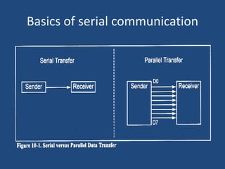
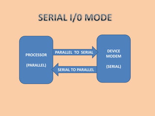
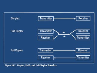
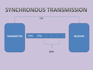
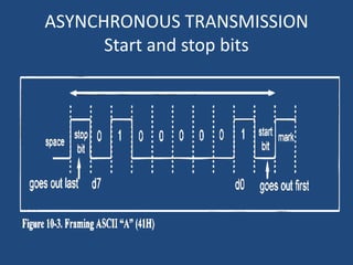
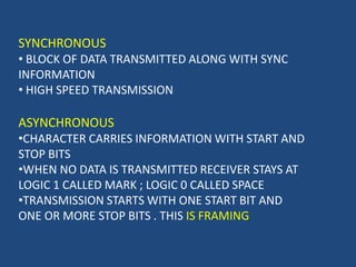
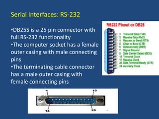
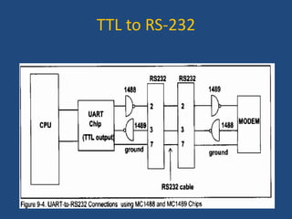
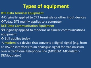
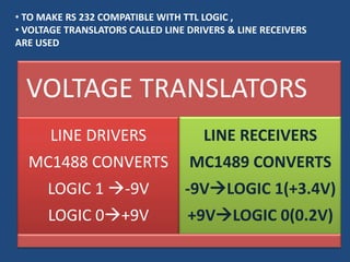
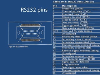
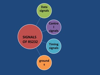
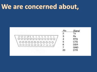
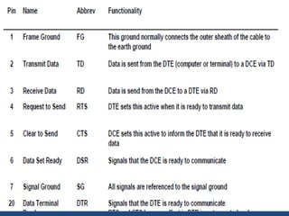
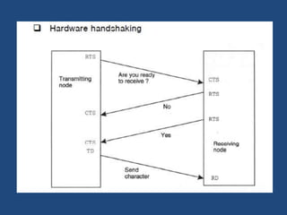
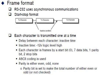
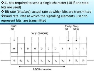
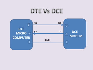
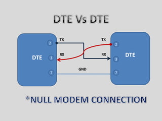
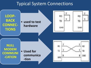
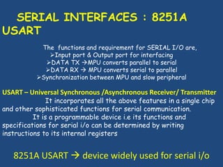
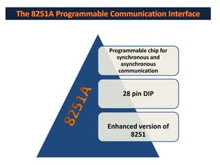
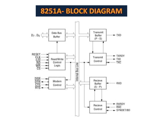
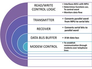
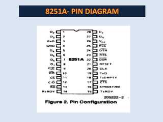
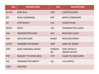
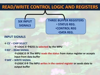
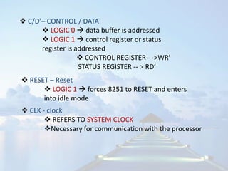
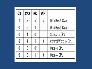
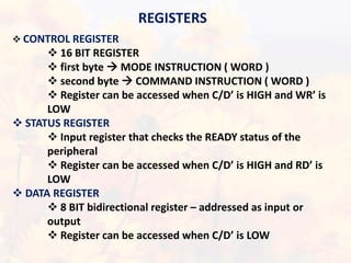
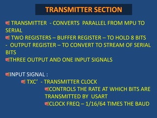
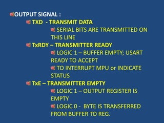
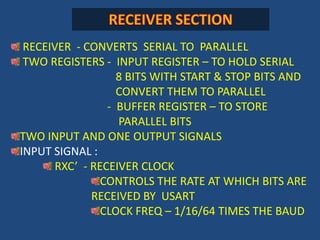
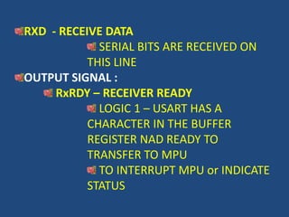
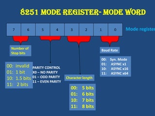
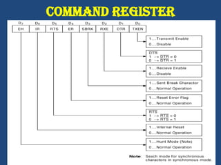
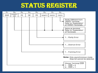
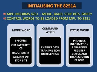
SERIAL I/O WITH 8085
Basics of serial communication
SERIAL I/0 MODEDEVICEMODEM(SERIAL)PROCESSOR(PARALLEL)PARALLEL  TO  SERIALSERIAL TO PARALLEL
SYNCHRONOUS TRANSMISSIONCLKTRANSMITTERRECEIVERSYNCSYNCDATA
ASYNCHRONOUS TRANSMISSIONStart and stop bits
SYNCHRONOUS  BLOCK OF DATA TRANSMITTED ALONG WITH SYNC INFORMATION
 HIGH SPEED TRANSMISSIONASYNCHRONOUSCHARACTER CARRIES INFORMATION WITH START AND STOP BITS
WHEN NO DATA IS TRANSMITTED RECEIVER STAYS AT LOGIC 1 CALLED MARK ; LOGIC 0 CALLED SPACE
TRANSMISSION STARTS WITH ONE START BIT AND ONE OR MORE STOP BITS . THIS IS FRAMINGSerial Interfaces: RS-232DB25S is a 25 pin connector withfull RS-232 functionalityThe computer socket has a femaleouter casing with male connectingpinsThe terminating cable connectorhas a male outer casing withfemale connecting pins
TTL to RS-232
Types of equipmentDTE Data Terminal EquipmentOriginally applied to CRT terminals or other input devices
Today, DTE mainly applies to a computerDCE Data Communication EquipmentOriginally applied to modems or similar communicationsequipment Still applies today A modem is a device that converts a digital signal (e.g. froman RS232 interface) to an analogue signal for transmissionover a traditional telephone line (MODEM: MOdulator-DEModulator)
VOLTAGE LEVEL +3V TO +15 VLOGIC 0VOLTAGE LEVEL -3V TO -15 VLOGIC 1YEP…. THATS RIGHT…..HERE WE USENEGATIVE TRUE LOGICBUT USUSALLY LOGIC 1  +12VLOGIC 0-12V????!!!!!!
 TO MAKE RS 232 COMPATIBLE WITH TTL LOGIC ,
 VOLTAGE TRANSLATORS CALLED LINE DRIVERS & LINE RECEIVERS ARE USEDRS232 pins
SIGNALS OF RS232
We are concerned about,
11 bits required to send a single character (10 if one stop bits are used)
 Bit rate (bits/sec): actual rate at which bits are transmitted
Baud rate: rate at which the signalling elements, used to represent bits, are transmittedDTE Vs DCEDCE   MODEMDTEMICROCOMPUTERTXRX22TXRX33GND77
DTE Vs DTEDTEDTETXTX22RXRX33GND77*NULL MODEM CONNECTION
Typical System Connections77
   SERIAL INTERFACES : 8251A USART         The  functions and requirement for SERIAL I/O are,Input port & Output port for interfacing
DATA TX MPU converts parallel to serial
DATA RX  MPU converts serial to parallel
Synchronization between MPU and slow peripheralUSART – Universal Synchronous /Asynchronous Receiver/ Transmitter                     It incorporates all the above features in a single chip and other sophisticated functions for serial communication.	    It is a programmable device i.e its functions and specifications for serial i/o can be determined by writing instructions to its internal registers8251A USART  device widely used for serial i/o
The 8251A Programmable Communication Interface8251A
8251A- BLOCK DIAGRAM
8251A- PIN DIAGRAM
READ/WRITE CONTROL LOGIC AND REGISTERSSIX INPUT SIGNALSTHREE BUFFER REGISTERS STATUS REG.
CONTROL REG
DATA REG.INPUT SIGNALSCS’ – CHIP SELECT
 LOGIC 0 8251 is selected by the MPU
RD’ – READ SIGNAL
LOGIC 0  The MPU reads the status from status register or accepts input from data buffer

Serial Io