


![ If the angle of Depression B to A is measured,
AC'=D tan β [ BC'= D ]
True difference in elevation between A & B,
H = AA'
= AC’ – A’C’
= D tan β - 0.0673 D2 ....(2)
10](https://image.slidesharecdn.com/3-210127095420/75/3-TRIGONOMETRIC-LEVELLING-SUR-3140601-GTU-10-2048.jpg)
![ Adding equation (1) & (2),
H = D tan α + D tan β
H = D/2 [tan α + D tan β] ..... (3)
From equation (3), it can be seen that by reciprocal method of
observation, the correction for earth’s curvature and refraction
can be eliminated.
R.L of station B = R.L. of station A + H
= R.L. of station A + D/2 [tan α + D tan β]
11](https://image.slidesharecdn.com/3-210127095420/75/3-TRIGONOMETRIC-LEVELLING-SUR-3140601-GTU-11-2048.jpg)


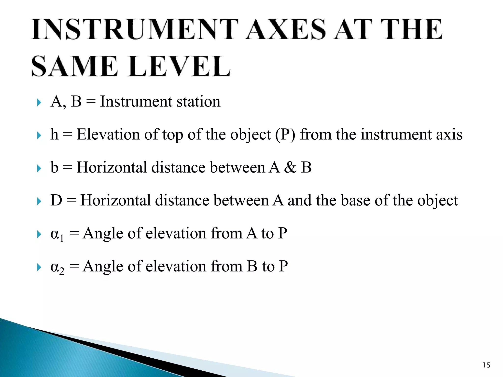


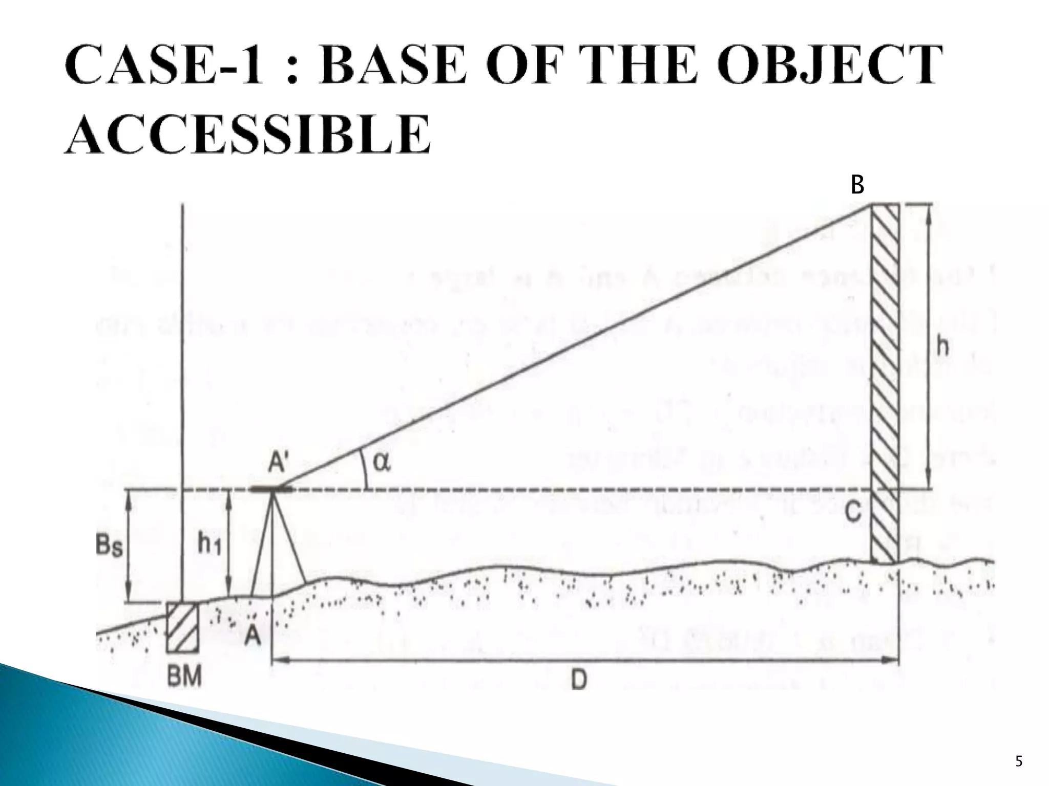
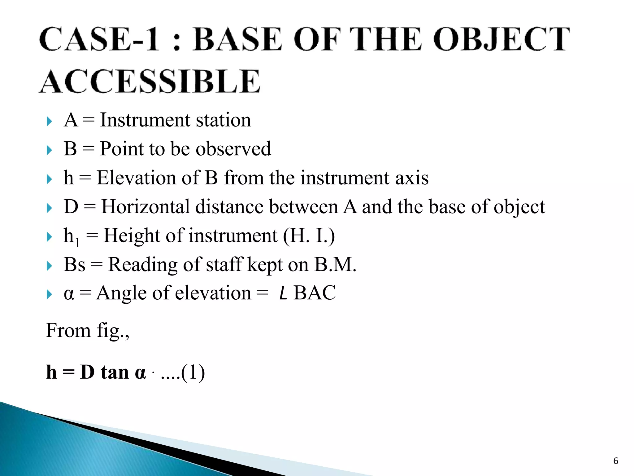
This document describes the method of indirect leveling using a theodolite to determine relative heights of points. There are three cases: [1] when the base of the object is accessible, [2] when the base is inaccessible but the instrument stations and object are in the same vertical plane, and [3] when the base is inaccessible and stations/object are not in the same plane. Corrections must be applied for earth's curvature and refraction over long distances. The reciprocal method can be used to eliminate these corrections. Equations are provided to calculate elevations of points for each case.
Introduction to the presentation by Asst. Prof. Vatsal D. Patel from Mahatma Gandhi Institute.
Explains indirect levelling for determining elevations using vertical angles and distances, detailing three cases for different access scenarios.
Introduces equations for calculating relative levels (R.L.) of points based on angles of elevation and distance, considering corrections.
Describes scenarios with varying heights of instrument axes during indirect measurements and their implications.
Details mathematical derivations for height differences based on angles of elevation using various equations.
Outlines the practical procedure for using the indirect levelling technique, including angle measurement and R.L. determination.
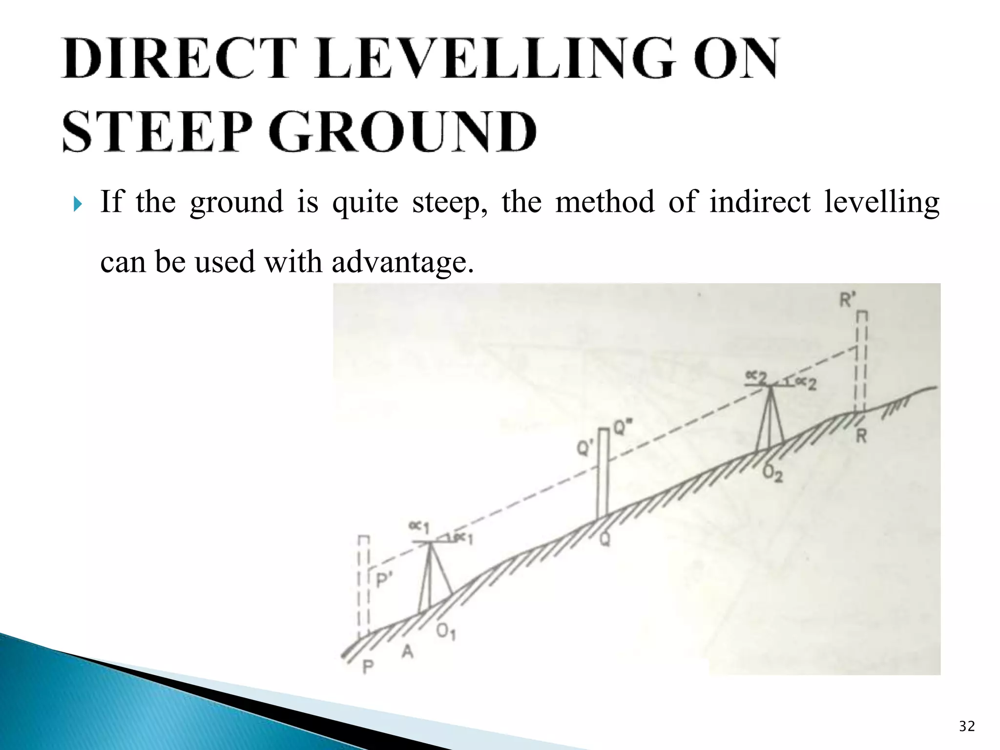
Presents the use of indirect levelling on steep slopes, detailing steps to determine elevation differences between points.


