SlideShare a Scribd company logo
TACHEOMETRIC SURVEYING
Tacheometry or tachemetry or telemetry is a branch of angular
surveying in which the horizontal and Vertical distances of points are
obtained by optical means as opposed to the ordinary slower process
of measurements by tape or chain.
• The method is very rapid and convenient.
• It is best adapted in obstacles such as steep and broken ground,
deep revines, stretches of water or swamp and so on, which make
chaining difficult or impossible,
• The primary object of tacheometry is the preparation of contoured
maps or plans requiring both the horizontal as well as Vertical
control. Also, on surveys of higher accuracy, it provides a check on
distances measured with the tape.
Tacheometry (from Greek, quick measure), is a system of
rapid surveying, by which the positions, both horizontal
and vertical, of points on the earth surface relatively to
one another are determined without using a chain or tape
or a separate leveling instrument.
Uses of Tacheometry
The tacheometric methods of surveying are used with
advantage over the direct methods of measurement of horizontal
distances and differences in elevations. Some of the uses are:
 Preparation of topographic maps which require both elevations and
horizontal distances.
 Survey work in difficult terrain where direct methods are
inconvenient
 Detail filling
 Reconnaissance surveys for highways, railways, etc.
 Checking of already measured distances
 Hydrographic surveys and
 Establishing secondary control.
INSTRUMENTS
-An ordinary transit theodolite fitted with a stadia diaphragm is generally used
for tacheometric survey.
- The stadia diaphragm essentially consists of one stadia hair above and the
other an equal distance below the horizontal cross-hair, the stadia hairs being
mounted in the ring and on the same vertical plane as the horizontal and
vertical cross-hairs.
Different forms of stadia diaphragm commonly used
Stadia is a tacheometric form of distance measurement that relies on fixed
angle intercept.
The telescope used in stadia surveying are of three kinds:
(1) The simple external-focusing telescope
(2) the external-focusing anallactic telescope (Possor`s telescope)
(3) the internal-focusing telescope.
A tacheometer must essentially incorporate the following features:
(i) The multiplying constant should have a nominal value of 100 and the error
contained in this value should not exceed 1 in 1000.
(ii) The axial horizontal line should be exactly midway between the other two
lines.
(iii) The telescope should be truly anallactic.
(iv) The telescope should be powerful having a magnification of 20 to 30
diameters.
• The aperture of the objective should be 35 to 45 mm in diameter to have a
sufficiently bright image.
• For small distances (say upto 100 meters), ordinary levelling staff may be
used. For greater distances a stadia rod may be used.
• A stadia rod is usually of one piece, having 3 – 5 meters length.
• A stadia rod graduated in 5 mm (i.e. 0.005 m) for smaller distances and while
for longer distances, the rod may be graduated in 1 cm (i.e. 0.01 m).
10' 7"
Different systems of Tacheometric Measurement:
The various systems of tacheometric survey may be classified as
follows:
 The stadia System
(a) Fixed Hair method of Stadia method
(b) Movable hair method, or Subtense method
 The tangential system
 Measurements by means of special instruments
The principle common to all the systems is to calculate the horizontal
distance between two points A and B and their distances in elevation, by
observing
(i) The angle at the instrument at A subtended by a known short distance
along a staff kept at B, and
(ii) the vertical angle to B from A.
(a) Fixed hair method
 In this method, the angle at the instrument at A
subtended by a known short distance along a staff kept at
B is made with the help of a stadia diaphragm having
stadia wires at fixed or constant distance apart.
 The readings are on the staff corresponding to all the
three wires taken.
 The staff intercept, i.e., the difference of the readings
corresponding to top and bottom stadia wires will
therefore depend on the distance of the staff from the
instrument.
 When the staff intercept is more than the length of the
staff, only half intercept is read.
 For inclined sight, readings may be taken by keeping
the staff either vertical or normal to the line of sight.
 This is the most common method is tacheometry and
the same ‘stadia method’ generally bears reference to this
method.
Subtense Method
 This method is similar to the fixed hair method except that the stadia
interval is variable.
 Suitable arrangement is made to vary the distance between the stadia hair
as to set them against the two targets on the staff kept at the point under
observation.
 Thus, in this case, the staff intercept, i.e., the distance between the two
targets is kept fixed while the stadia interval, i.e., the distance between the
stadia hair is variable.
 As in the case of fixed hair method, inclined sights may also be taken.
Tangential Method
 In this method, the stadia hairs are not used, the readings being taken
against the horizontal cross-hair.
 To measure the staff intercept, two pointings of the instruments are,
therefore, necessary.
 This necessitates measurement of vertical angles twice for one single
observation.
PRINCIPLE OF STADIA METHOD
The stadia method is based on the principle that the ratio of the
perpendicular to the base is constant in similar isosceles triangles.
A
O
A2
A1
B2
B1
B
C2 C1 C
)
β
In figure, let two rays OA and OB be equally inclined to central ray OC.
Let A2B2, A1B1 and AB be the staff intercepts. Evidently,
OC2
A2B2
OC1
A1B1
OC
AB
= =
= constant k = ½ cot
β
2
This constant k entirely depends upon the magnitude of the angle β.
 In actual practice, observations may be made with either horizontal line of
sight or with inclined line of sight.
 In the later case the staff may be kept either vertically or normal to the line
of sight.
 First the distance-elevation formulae for the horizontal sights should be
derived.
Horizontal Sights:
i
.
f2
f1
s
O
d
M
b
C
B
A
c
a
D
Consider the figure, in which O is the optical centre of the objective of an
external focusing telescope.
Let A, C, and B = the points cut by the three lines of sight corresponding to
three wires.
b, c, and a = top, axial and bottom hairs of the diaphragm.
ab = i = interval b/w the stadia hairs (stadia interval)
AB = s = staff intercept;
f = focal length of the objective
f1 = horizontal distance of the staff from the optical centre of the objective
f2 = horizontal distance of the cross-wires from O.
d = distance of the vertical axis of the instrument from O.
D = horizontal distance of the staff from the vertical axis of the instruments.
M = centre of the instrument, corresponding to the vertical axis.
Since the rays BOb and AOa pass through the optical centre, they are straight so
that AOB and aOb are similar. Hence,
f1 s
f2 i
=
Again, since f1 and f2 are conjugate focal distances, we have from lens formula,
1 1 1
f f2 f1
+=
Multiplying throughout by ff1, we get f1 = f + f
f1
f2
Substituting the values of in the above, we get
f1 s
f2 i
=
f1 = f + f
s
i
Horizontal distance between the axis and the staff is D = f1 + d
D = s + (f + d) = k . s + C
f
i
Above equation is known as the distance equation. In order to get the
horizontal distance, therefore, the staff intercept s is to be found by subtracting
the staff readings corresponding to the top and bottom stadia hairs.
The constant k = f/i is known as the multiplying constant or stadia interval
factor and the constant (f + d) = C is known as the additive constant of the
instrument.
Determination of constant k and C
The values of the multiplying constant k and the additive constant C can be
computed by the following methods:
1st
method:
In this method, the additive constant C = (f + d) is measured from the
instrument while the multiplying constant k is computed from field
observations:
1. Focus the instrument to a distant object and measure along the telescope
the distance between the objective and cross-hairs,
2. The distance d between the instrument axis and the objective is variable in
the case of external focusing telescope, being greater for short sights and
smaller for long sights. It should, therefore be measured for average sight.
Thus, the additive constant (f + d) is known.
1 1 1
f f1 f2
+=
3. To calculate the multiplying constant k, measure a known distance D1 and
take the intercept s1 on the staff kept at that point, the line of sight being
horizontal. Using the equation,
D1 = ks1 + C or k =
For average value, staff intercepts, s2, s3 etc., can be measured
corresponding to distance D2, D3 etc., and mean value can be calculated.
Note: In case of some external focusing instruments, the eye-piece-diaphragm
unit moves during focusing. For such instruments d is constant and does not
vary while focusing.
D1 – C
s
2nd method:
In this method, both the constants are determined by field observations as
under:
1. Measure a line, about 200m long, on fairly level ground and drive pegs at
some interval, say 50 meters.
2. Keep the staff on the pegs and observe the corresponding staff intercepts
with horizontal sight.
3. Knowing the values of D and s for different points, a number of
simultaneous equations can be formed by substituting the values of D and s
in equation D = k.s + C. The simultaneous solution of successive pairs will
give the values of k and C, and the average of these can be found.
For example, if s1 is the staff intercept corresponding to distance D1 and s2
corresponding to D2 we have,
D1 = k.s1 + C . . . . . (i) and D2 = k. s2 + C . . . . . (ii)
Subtracting (i) from (ii), we get
k =
D2 – D1
s2 – s1
. . . . . . . . . (1)
Substituting the values of k in (i), we get
C = D1 - s1
D2 – D1
s2 – s1
=
D1s2 – D2s1
s2 – s1
. . . . . . . . . (2)
Thus equation (1) and (2) give the values of k and C.
Distance and Elevation formulae for Staff Vertical : Inclined SightDistance and Elevation formulae for Staff Vertical : Inclined Sight
Let P = Instrument station; Q = Staff station
M = position of instruments axis; O = Optical centre of the objective
A, C, B = Points corresponding to the readings of the three hairs
s = AB = Staff intercept; i = Stadia interval
Ө = Inclination of the line of sight from the horizontal
L = Length MC measured along the line of sight
D = MQ’ = Horizontal distance between the instrument and the staff
V = Vertical intercept at Q, between the line of sight and the horizontal line
h = height of the instrument; r = central hair reading
β = angle between the two extreme rays corresponding to stadia hairs.
• Draw a line A’CB’ normal to the line of sight OC.
• Angle AA`C = 900
+ β/2, being the exterior angle of the ∆COA`.
• Similarly, from ∆COB`, angle OB`C = angle BB`C = 900
– β/2.
h
B
A
O
D
P
A`
C
B`
Q
Q`
M
r
V
Ө
β
L
Ө
Since β/2 is very small (its value being equal to 17’ 11” for k = 100), angle AA’C
and angle BB’C may be approximately taken equal to 900
.
∟AA’C = ∟BB’C = 900
From ∆ ACA’, A’C = AC cos Ө or A’B’ = AB cos Ө = s cos Ө ……….(a)
Since the line A’B’ is perpendicular to the line of sight OC, equation D = k s + C
is directly applicable. Hence, we have
MC = L = k . A’B’ + C = k s cosӨ + C . . . . . . . (b)
The horizontal distance
D = L cosӨ = (k s cosӨ + C) cosӨ
D = k s cos2
Ө + C cosӨ . . . . . . (1)
Similarly, V = L sin Ө = (k s cosӨ + C) sinӨ = k s cosӨ . sinӨ + C sinӨ
V = k s + C sinӨ
sin2Ө
2
. . . . . . (2)
Thus equations (1) and (2) are the distance and elevation formulae for inclined line
of sight.
(a) Elevation of the staff station for angle of elevationElevation of the staff station for angle of elevation
If the line of sight has an angle of elevation Ө, as shown in the figure, we
have
Elevation of staff station = Elevation of instrument station + h + V – r.
(b) Elevation of the staff station for the angle of depression:
Elevation of Q = Elevation of P + h – V - r
Distance and Elevation formulae for Staff Normal : Inclined SightDistance and Elevation formulae for Staff Normal : Inclined Sight
h
B
A
O
D
P
C
C`
Q
Q`
M
rcosӨ
V
Ө
β
L
Ө
L cosӨ rsinӨ
Figure shows the case when the staff is held normal to the line of sight.
Case (a): Line of Sight at an angle of elevation Ө
Let AB = s = staff intercept;
CQ = r = axial hair reading
With the same notations as in the last case, we have
MC = L = K s + C
The horizontal distance between P and Q is given by
D = MC’ + C’Q’ = L cosӨ + r sinӨ
= (k s + C) cosӨ + r sinӨ . . . . . (3)
Similarly, V = L sinӨ = (k s + C) sinӨ . . . . . (4)
Case (a): Line of Sight at an angle of depression Ө
rsinӨ
M
P
h
Ө
A
C
C’
Q
Q’
B
C1
D
L cosӨ
rcosӨ
V
O
Figure shows the line of sight depressed downwards,
MC = L = k s + C
D = MQ’ = MC’ – Q’C’
= L cosӨ - r sinӨ
D = (k s + C) cosӨ - r sinӨ . . . . . (5)
V = L sinӨ = (k s + C) sinӨ
. . . . . (6)
Elevation of Q = Elevation of P + h – V – r cosӨ

More Related Content

What's hot

Triangulation survey
Triangulation surveyTriangulation survey
Triangulation survey
HastarajPandey
 
Reciprocal ranging or Indirect Ranging
Reciprocal ranging or Indirect RangingReciprocal ranging or Indirect Ranging
Reciprocal ranging or Indirect Ranging
Mujeeb Muji
 
Tacheometric survey
Tacheometric surveyTacheometric survey
Tacheometric survey
Student
 
Chain surveying
Chain surveyingChain surveying
Chain surveying
JNTUK
 
Tacheometric surveying ppt
Tacheometric surveying pptTacheometric surveying ppt
Tacheometric surveying ppt
Naufil Sayyad
 
Theodolite surveying
Theodolite surveying Theodolite surveying
Theodolite surveying
neharajpl
 
Theodolite angle measurement
Theodolite angle measurementTheodolite angle measurement
Theodolite angle measurement
Mujeeb Muji
 
Levelling
LevellingLevelling
Levelling in Surveying
Levelling in SurveyingLevelling in Surveying
Levelling in Surveying
RAHUL SINHA
 
1.1 Linear measurement original: Chaining & Ranging
1.1 Linear measurement original: Chaining & Ranging1.1 Linear measurement original: Chaining & Ranging
1.1 Linear measurement original: Chaining & Ranging
Rakesh Verma
 
Electronic distance measurement (EDM)
Electronic distance measurement (EDM)Electronic distance measurement (EDM)
Electronic distance measurement (EDM)
Bathla Tuition Centre
 
EDM
EDMEDM
Contouring
ContouringContouring
Contouring
GAURAV. H .TANDON
 
Surveying ppt : COMPONENETS OF TRANSIT THEODOLITE
Surveying ppt : COMPONENETS OF TRANSIT  THEODOLITESurveying ppt : COMPONENETS OF TRANSIT  THEODOLITE
Surveying ppt : COMPONENETS OF TRANSIT THEODOLITE
Sukhvinder Singh
 
Curves and there application in Survey
Curves and there application in SurveyCurves and there application in Survey
Curves and there application in Survey
Lord1911
 
Curve setting ppt
Curve setting pptCurve setting ppt
Curve setting ppt
Naufil Sayyad
 
Setting out of curve (Survey)
Setting out of curve (Survey)Setting out of curve (Survey)
Setting out of curve (Survey)
Bhavik Patel
 
Total Station surveying
Total Station surveyingTotal Station surveying
Total Station surveying
RAMPRASAD KUMAWAT
 
Theodolite survey
Theodolite surveyTheodolite survey
Theodolite survey
Umarfarook Momin
 
Theodolite surveying
Theodolite surveying Theodolite surveying
Theodolite surveying
neharajpl
 

What's hot (20)

Triangulation survey
Triangulation surveyTriangulation survey
Triangulation survey
 
Reciprocal ranging or Indirect Ranging
Reciprocal ranging or Indirect RangingReciprocal ranging or Indirect Ranging
Reciprocal ranging or Indirect Ranging
 
Tacheometric survey
Tacheometric surveyTacheometric survey
Tacheometric survey
 
Chain surveying
Chain surveyingChain surveying
Chain surveying
 
Tacheometric surveying ppt
Tacheometric surveying pptTacheometric surveying ppt
Tacheometric surveying ppt
 
Theodolite surveying
Theodolite surveying Theodolite surveying
Theodolite surveying
 
Theodolite angle measurement
Theodolite angle measurementTheodolite angle measurement
Theodolite angle measurement
 
Levelling
LevellingLevelling
Levelling
 
Levelling in Surveying
Levelling in SurveyingLevelling in Surveying
Levelling in Surveying
 
1.1 Linear measurement original: Chaining & Ranging
1.1 Linear measurement original: Chaining & Ranging1.1 Linear measurement original: Chaining & Ranging
1.1 Linear measurement original: Chaining & Ranging
 
Electronic distance measurement (EDM)
Electronic distance measurement (EDM)Electronic distance measurement (EDM)
Electronic distance measurement (EDM)
 
EDM
EDMEDM
EDM
 
Contouring
ContouringContouring
Contouring
 
Surveying ppt : COMPONENETS OF TRANSIT THEODOLITE
Surveying ppt : COMPONENETS OF TRANSIT  THEODOLITESurveying ppt : COMPONENETS OF TRANSIT  THEODOLITE
Surveying ppt : COMPONENETS OF TRANSIT THEODOLITE
 
Curves and there application in Survey
Curves and there application in SurveyCurves and there application in Survey
Curves and there application in Survey
 
Curve setting ppt
Curve setting pptCurve setting ppt
Curve setting ppt
 
Setting out of curve (Survey)
Setting out of curve (Survey)Setting out of curve (Survey)
Setting out of curve (Survey)
 
Total Station surveying
Total Station surveyingTotal Station surveying
Total Station surveying
 
Theodolite survey
Theodolite surveyTheodolite survey
Theodolite survey
 
Theodolite surveying
Theodolite surveying Theodolite surveying
Theodolite surveying
 

Similar to tacheometric surveying

Tacheometric-Surveying.ppt
Tacheometric-Surveying.pptTacheometric-Surveying.ppt
Tacheometric-Surveying.ppt
ADCET, Ashta
 
UNIT 1.pptx
UNIT 1.pptxUNIT 1.pptx
UNIT 1.pptx
mrunmayee20
 
tacheometric-surveying.pdf
tacheometric-surveying.pdftacheometric-surveying.pdf
tacheometric-surveying.pdf
MaureenNassanga
 
Laboratory manual surveying_ii
Laboratory manual surveying_iiLaboratory manual surveying_ii
Laboratory manual surveying_ii
Dr. BASWESHWAR JIRWANKAR
 
tacheometry surveying
tacheometry surveyingtacheometry surveying
tacheometry surveying
Jayachandra Jitendra
 
Tachymetry survey POLITEKNIK MELAKA
Tachymetry survey POLITEKNIK MELAKATachymetry survey POLITEKNIK MELAKA
Tachymetry survey POLITEKNIK MELAKARiezat Zainal
 
6. TACHOMETRIC SURVEYING (SUR) 3140601 GTU
6. TACHOMETRIC SURVEYING (SUR) 3140601 GTU6. TACHOMETRIC SURVEYING (SUR) 3140601 GTU
6. TACHOMETRIC SURVEYING (SUR) 3140601 GTU
VATSAL PATEL
 
Unit 1 Part 2 Thacheomatric Surveying..pptx
Unit 1 Part 2 Thacheomatric Surveying..pptxUnit 1 Part 2 Thacheomatric Surveying..pptx
Unit 1 Part 2 Thacheomatric Surveying..pptx
CE01NayanRathod
 
Tacheometry 1
Tacheometry 1Tacheometry 1
Tacheometry 1
clinton amunga
 
S2 6 theodolites
S2 6 theodolitesS2 6 theodolites
S2 6 theodolites
Est
 
3140601_surveying_module-6-tacheometric-surveying.pdf
3140601_surveying_module-6-tacheometric-surveying.pdf3140601_surveying_module-6-tacheometric-surveying.pdf
3140601_surveying_module-6-tacheometric-surveying.pdf
Deepak37004
 
Tacheometry for Geomatics Enginering.pptx
Tacheometry for Geomatics Enginering.pptxTacheometry for Geomatics Enginering.pptx
Tacheometry for Geomatics Enginering.pptx
CtKamariahMdSaat
 
Group 1.pptx
Group 1.pptxGroup 1.pptx
Group 1.pptx
NkosilamiMguni
 
Radiacion poligonal abierta
Radiacion   poligonal abiertaRadiacion   poligonal abierta
Radiacion poligonal abierta
JeanCordova7
 
surveying ii
surveying iisurveying ii
surveying ii
Gowtham Raja
 
Project 2- traversing
Project 2- traversingProject 2- traversing
Project 2- traversing
seenyee
 
Project 2- traversing
Project 2- traversingProject 2- traversing
Project 2- traversing
seenyee
 
Module 1 tacheometry
Module 1 tacheometryModule 1 tacheometry
Module 1 tacheometry
Dr. BASWESHWAR JIRWANKAR
 
Site surveying report 2
Site surveying report 2Site surveying report 2
Site surveying report 2
Doreen Yeo
 
TACHEOMETRY 1. btech civil engineeringpptx
TACHEOMETRY 1. btech civil engineeringpptxTACHEOMETRY 1. btech civil engineeringpptx
TACHEOMETRY 1. btech civil engineeringpptx
Ayushsharma131736
 

Similar to tacheometric surveying (20)

Tacheometric-Surveying.ppt
Tacheometric-Surveying.pptTacheometric-Surveying.ppt
Tacheometric-Surveying.ppt
 
UNIT 1.pptx
UNIT 1.pptxUNIT 1.pptx
UNIT 1.pptx
 
tacheometric-surveying.pdf
tacheometric-surveying.pdftacheometric-surveying.pdf
tacheometric-surveying.pdf
 
Laboratory manual surveying_ii
Laboratory manual surveying_iiLaboratory manual surveying_ii
Laboratory manual surveying_ii
 
tacheometry surveying
tacheometry surveyingtacheometry surveying
tacheometry surveying
 
Tachymetry survey POLITEKNIK MELAKA
Tachymetry survey POLITEKNIK MELAKATachymetry survey POLITEKNIK MELAKA
Tachymetry survey POLITEKNIK MELAKA
 
6. TACHOMETRIC SURVEYING (SUR) 3140601 GTU
6. TACHOMETRIC SURVEYING (SUR) 3140601 GTU6. TACHOMETRIC SURVEYING (SUR) 3140601 GTU
6. TACHOMETRIC SURVEYING (SUR) 3140601 GTU
 
Unit 1 Part 2 Thacheomatric Surveying..pptx
Unit 1 Part 2 Thacheomatric Surveying..pptxUnit 1 Part 2 Thacheomatric Surveying..pptx
Unit 1 Part 2 Thacheomatric Surveying..pptx
 
Tacheometry 1
Tacheometry 1Tacheometry 1
Tacheometry 1
 
S2 6 theodolites
S2 6 theodolitesS2 6 theodolites
S2 6 theodolites
 
3140601_surveying_module-6-tacheometric-surveying.pdf
3140601_surveying_module-6-tacheometric-surveying.pdf3140601_surveying_module-6-tacheometric-surveying.pdf
3140601_surveying_module-6-tacheometric-surveying.pdf
 
Tacheometry for Geomatics Enginering.pptx
Tacheometry for Geomatics Enginering.pptxTacheometry for Geomatics Enginering.pptx
Tacheometry for Geomatics Enginering.pptx
 
Group 1.pptx
Group 1.pptxGroup 1.pptx
Group 1.pptx
 
Radiacion poligonal abierta
Radiacion   poligonal abiertaRadiacion   poligonal abierta
Radiacion poligonal abierta
 
surveying ii
surveying iisurveying ii
surveying ii
 
Project 2- traversing
Project 2- traversingProject 2- traversing
Project 2- traversing
 
Project 2- traversing
Project 2- traversingProject 2- traversing
Project 2- traversing
 
Module 1 tacheometry
Module 1 tacheometryModule 1 tacheometry
Module 1 tacheometry
 
Site surveying report 2
Site surveying report 2Site surveying report 2
Site surveying report 2
 
TACHEOMETRY 1. btech civil engineeringpptx
TACHEOMETRY 1. btech civil engineeringpptxTACHEOMETRY 1. btech civil engineeringpptx
TACHEOMETRY 1. btech civil engineeringpptx
 

More from Mujeeb Muji

Axial flow reaction turbines/ Kaplan Turbine
Axial flow reaction turbines/ Kaplan TurbineAxial flow reaction turbines/ Kaplan Turbine
Axial flow reaction turbines/ Kaplan Turbine
Mujeeb Muji
 
Water Supply and Treatment Engineering- Module 1
Water Supply and Treatment Engineering- Module 1Water Supply and Treatment Engineering- Module 1
Water Supply and Treatment Engineering- Module 1
Mujeeb Muji
 
Fluids mechanics class 1 -Module 1
Fluids mechanics class 1 -Module 1Fluids mechanics class 1 -Module 1
Fluids mechanics class 1 -Module 1
Mujeeb Muji
 
Compass surveying
Compass surveyingCompass surveying
Compass surveying
Mujeeb Muji
 
levelling
levellinglevelling
levelling
Mujeeb Muji
 
Theodolitetraversing
TheodolitetraversingTheodolitetraversing
Theodolitetraversing
Mujeeb Muji
 
Perpendicular Offset
Perpendicular Offset Perpendicular Offset
Perpendicular Offset
Mujeeb Muji
 
Direct Ranging
Direct RangingDirect Ranging
Direct Ranging
Mujeeb Muji
 
Introduction on instruments used for chaining
Introduction on instruments used for chainingIntroduction on instruments used for chaining
Introduction on instruments used for chaining
Mujeeb Muji
 
Aerial Photogrammetry
Aerial Photogrammetry Aerial Photogrammetry
Aerial Photogrammetry
Mujeeb Muji
 
Field Astronomy
Field AstronomyField Astronomy
Field Astronomy
Mujeeb Muji
 
Glass powder replacement for cement.by ananth k p coorg
Glass powder replacement for cement.by ananth k p coorgGlass powder replacement for cement.by ananth k p coorg
Glass powder replacement for cement.by ananth k p coorg
Mujeeb Muji
 

More from Mujeeb Muji (12)

Axial flow reaction turbines/ Kaplan Turbine
Axial flow reaction turbines/ Kaplan TurbineAxial flow reaction turbines/ Kaplan Turbine
Axial flow reaction turbines/ Kaplan Turbine
 
Water Supply and Treatment Engineering- Module 1
Water Supply and Treatment Engineering- Module 1Water Supply and Treatment Engineering- Module 1
Water Supply and Treatment Engineering- Module 1
 
Fluids mechanics class 1 -Module 1
Fluids mechanics class 1 -Module 1Fluids mechanics class 1 -Module 1
Fluids mechanics class 1 -Module 1
 
Compass surveying
Compass surveyingCompass surveying
Compass surveying
 
levelling
levellinglevelling
levelling
 
Theodolitetraversing
TheodolitetraversingTheodolitetraversing
Theodolitetraversing
 
Perpendicular Offset
Perpendicular Offset Perpendicular Offset
Perpendicular Offset
 
Direct Ranging
Direct RangingDirect Ranging
Direct Ranging
 
Introduction on instruments used for chaining
Introduction on instruments used for chainingIntroduction on instruments used for chaining
Introduction on instruments used for chaining
 
Aerial Photogrammetry
Aerial Photogrammetry Aerial Photogrammetry
Aerial Photogrammetry
 
Field Astronomy
Field AstronomyField Astronomy
Field Astronomy
 
Glass powder replacement for cement.by ananth k p coorg
Glass powder replacement for cement.by ananth k p coorgGlass powder replacement for cement.by ananth k p coorg
Glass powder replacement for cement.by ananth k p coorg
 

Recently uploaded

Democratizing Fuzzing at Scale by Abhishek Arya
Democratizing Fuzzing at Scale by Abhishek AryaDemocratizing Fuzzing at Scale by Abhishek Arya
Democratizing Fuzzing at Scale by Abhishek Arya
abh.arya
 
Water Industry Process Automation and Control Monthly - May 2024.pdf
Water Industry Process Automation and Control Monthly - May 2024.pdfWater Industry Process Automation and Control Monthly - May 2024.pdf
Water Industry Process Automation and Control Monthly - May 2024.pdf
Water Industry Process Automation & Control
 
一比一原版(SFU毕业证)西蒙菲莎大学毕业证成绩单如何办理
一比一原版(SFU毕业证)西蒙菲莎大学毕业证成绩单如何办理一比一原版(SFU毕业证)西蒙菲莎大学毕业证成绩单如何办理
一比一原版(SFU毕业证)西蒙菲莎大学毕业证成绩单如何办理
bakpo1
 
Sachpazis:Terzaghi Bearing Capacity Estimation in simple terms with Calculati...
Sachpazis:Terzaghi Bearing Capacity Estimation in simple terms with Calculati...Sachpazis:Terzaghi Bearing Capacity Estimation in simple terms with Calculati...
Sachpazis:Terzaghi Bearing Capacity Estimation in simple terms with Calculati...
Dr.Costas Sachpazis
 
COLLEGE BUS MANAGEMENT SYSTEM PROJECT REPORT.pdf
COLLEGE BUS MANAGEMENT SYSTEM PROJECT REPORT.pdfCOLLEGE BUS MANAGEMENT SYSTEM PROJECT REPORT.pdf
COLLEGE BUS MANAGEMENT SYSTEM PROJECT REPORT.pdf
Kamal Acharya
 
ASME IX(9) 2007 Full Version .pdf
ASME IX(9)  2007 Full Version       .pdfASME IX(9)  2007 Full Version       .pdf
ASME IX(9) 2007 Full Version .pdf
AhmedHussein950959
 
Planning Of Procurement o different goods and services
Planning Of Procurement o different goods and servicesPlanning Of Procurement o different goods and services
Planning Of Procurement o different goods and services
JoytuBarua2
 
Automobile Management System Project Report.pdf
Automobile Management System Project Report.pdfAutomobile Management System Project Report.pdf
Automobile Management System Project Report.pdf
Kamal Acharya
 
ethical hacking-mobile hacking methods.ppt
ethical hacking-mobile hacking methods.pptethical hacking-mobile hacking methods.ppt
ethical hacking-mobile hacking methods.ppt
Jayaprasanna4
 
Pile Foundation by Venkatesh Taduvai (Sub Geotechnical Engineering II)-conver...
Pile Foundation by Venkatesh Taduvai (Sub Geotechnical Engineering II)-conver...Pile Foundation by Venkatesh Taduvai (Sub Geotechnical Engineering II)-conver...
Pile Foundation by Venkatesh Taduvai (Sub Geotechnical Engineering II)-conver...
AJAYKUMARPUND1
 
Industrial Training at Shahjalal Fertilizer Company Limited (SFCL)
Industrial Training at Shahjalal Fertilizer Company Limited (SFCL)Industrial Training at Shahjalal Fertilizer Company Limited (SFCL)
Industrial Training at Shahjalal Fertilizer Company Limited (SFCL)
MdTanvirMahtab2
 
road safety engineering r s e unit 3.pdf
road safety engineering  r s e unit 3.pdfroad safety engineering  r s e unit 3.pdf
road safety engineering r s e unit 3.pdf
VENKATESHvenky89705
 
The Benefits and Techniques of Trenchless Pipe Repair.pdf
The Benefits and Techniques of Trenchless Pipe Repair.pdfThe Benefits and Techniques of Trenchless Pipe Repair.pdf
The Benefits and Techniques of Trenchless Pipe Repair.pdf
Pipe Restoration Solutions
 
Halogenation process of chemical process industries
Halogenation process of chemical process industriesHalogenation process of chemical process industries
Halogenation process of chemical process industries
MuhammadTufail242431
 
Courier management system project report.pdf
Courier management system project report.pdfCourier management system project report.pdf
Courier management system project report.pdf
Kamal Acharya
 
J.Yang, ICLR 2024, MLILAB, KAIST AI.pdf
J.Yang,  ICLR 2024, MLILAB, KAIST AI.pdfJ.Yang,  ICLR 2024, MLILAB, KAIST AI.pdf
J.Yang, ICLR 2024, MLILAB, KAIST AI.pdf
MLILAB
 
block diagram and signal flow graph representation
block diagram and signal flow graph representationblock diagram and signal flow graph representation
block diagram and signal flow graph representation
Divya Somashekar
 
WATER CRISIS and its solutions-pptx 1234
WATER CRISIS and its solutions-pptx 1234WATER CRISIS and its solutions-pptx 1234
WATER CRISIS and its solutions-pptx 1234
AafreenAbuthahir2
 
H.Seo, ICLR 2024, MLILAB, KAIST AI.pdf
H.Seo,  ICLR 2024, MLILAB,  KAIST AI.pdfH.Seo,  ICLR 2024, MLILAB,  KAIST AI.pdf
H.Seo, ICLR 2024, MLILAB, KAIST AI.pdf
MLILAB
 
Cosmetic shop management system project report.pdf
Cosmetic shop management system project report.pdfCosmetic shop management system project report.pdf
Cosmetic shop management system project report.pdf
Kamal Acharya
 

Recently uploaded (20)

Democratizing Fuzzing at Scale by Abhishek Arya
Democratizing Fuzzing at Scale by Abhishek AryaDemocratizing Fuzzing at Scale by Abhishek Arya
Democratizing Fuzzing at Scale by Abhishek Arya
 
Water Industry Process Automation and Control Monthly - May 2024.pdf
Water Industry Process Automation and Control Monthly - May 2024.pdfWater Industry Process Automation and Control Monthly - May 2024.pdf
Water Industry Process Automation and Control Monthly - May 2024.pdf
 
一比一原版(SFU毕业证)西蒙菲莎大学毕业证成绩单如何办理
一比一原版(SFU毕业证)西蒙菲莎大学毕业证成绩单如何办理一比一原版(SFU毕业证)西蒙菲莎大学毕业证成绩单如何办理
一比一原版(SFU毕业证)西蒙菲莎大学毕业证成绩单如何办理
 
Sachpazis:Terzaghi Bearing Capacity Estimation in simple terms with Calculati...
Sachpazis:Terzaghi Bearing Capacity Estimation in simple terms with Calculati...Sachpazis:Terzaghi Bearing Capacity Estimation in simple terms with Calculati...
Sachpazis:Terzaghi Bearing Capacity Estimation in simple terms with Calculati...
 
COLLEGE BUS MANAGEMENT SYSTEM PROJECT REPORT.pdf
COLLEGE BUS MANAGEMENT SYSTEM PROJECT REPORT.pdfCOLLEGE BUS MANAGEMENT SYSTEM PROJECT REPORT.pdf
COLLEGE BUS MANAGEMENT SYSTEM PROJECT REPORT.pdf
 
ASME IX(9) 2007 Full Version .pdf
ASME IX(9)  2007 Full Version       .pdfASME IX(9)  2007 Full Version       .pdf
ASME IX(9) 2007 Full Version .pdf
 
Planning Of Procurement o different goods and services
Planning Of Procurement o different goods and servicesPlanning Of Procurement o different goods and services
Planning Of Procurement o different goods and services
 
Automobile Management System Project Report.pdf
Automobile Management System Project Report.pdfAutomobile Management System Project Report.pdf
Automobile Management System Project Report.pdf
 
ethical hacking-mobile hacking methods.ppt
ethical hacking-mobile hacking methods.pptethical hacking-mobile hacking methods.ppt
ethical hacking-mobile hacking methods.ppt
 
Pile Foundation by Venkatesh Taduvai (Sub Geotechnical Engineering II)-conver...
Pile Foundation by Venkatesh Taduvai (Sub Geotechnical Engineering II)-conver...Pile Foundation by Venkatesh Taduvai (Sub Geotechnical Engineering II)-conver...
Pile Foundation by Venkatesh Taduvai (Sub Geotechnical Engineering II)-conver...
 
Industrial Training at Shahjalal Fertilizer Company Limited (SFCL)
Industrial Training at Shahjalal Fertilizer Company Limited (SFCL)Industrial Training at Shahjalal Fertilizer Company Limited (SFCL)
Industrial Training at Shahjalal Fertilizer Company Limited (SFCL)
 
road safety engineering r s e unit 3.pdf
road safety engineering  r s e unit 3.pdfroad safety engineering  r s e unit 3.pdf
road safety engineering r s e unit 3.pdf
 
The Benefits and Techniques of Trenchless Pipe Repair.pdf
The Benefits and Techniques of Trenchless Pipe Repair.pdfThe Benefits and Techniques of Trenchless Pipe Repair.pdf
The Benefits and Techniques of Trenchless Pipe Repair.pdf
 
Halogenation process of chemical process industries
Halogenation process of chemical process industriesHalogenation process of chemical process industries
Halogenation process of chemical process industries
 
Courier management system project report.pdf
Courier management system project report.pdfCourier management system project report.pdf
Courier management system project report.pdf
 
J.Yang, ICLR 2024, MLILAB, KAIST AI.pdf
J.Yang,  ICLR 2024, MLILAB, KAIST AI.pdfJ.Yang,  ICLR 2024, MLILAB, KAIST AI.pdf
J.Yang, ICLR 2024, MLILAB, KAIST AI.pdf
 
block diagram and signal flow graph representation
block diagram and signal flow graph representationblock diagram and signal flow graph representation
block diagram and signal flow graph representation
 
WATER CRISIS and its solutions-pptx 1234
WATER CRISIS and its solutions-pptx 1234WATER CRISIS and its solutions-pptx 1234
WATER CRISIS and its solutions-pptx 1234
 
H.Seo, ICLR 2024, MLILAB, KAIST AI.pdf
H.Seo,  ICLR 2024, MLILAB,  KAIST AI.pdfH.Seo,  ICLR 2024, MLILAB,  KAIST AI.pdf
H.Seo, ICLR 2024, MLILAB, KAIST AI.pdf
 
Cosmetic shop management system project report.pdf
Cosmetic shop management system project report.pdfCosmetic shop management system project report.pdf
Cosmetic shop management system project report.pdf
 

tacheometric surveying

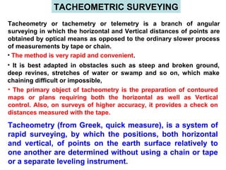
  • 1. TACHEOMETRIC SURVEYING Tacheometry or tachemetry or telemetry is a branch of angular surveying in which the horizontal and Vertical distances of points are obtained by optical means as opposed to the ordinary slower process of measurements by tape or chain. • The method is very rapid and convenient. • It is best adapted in obstacles such as steep and broken ground, deep revines, stretches of water or swamp and so on, which make chaining difficult or impossible, • The primary object of tacheometry is the preparation of contoured maps or plans requiring both the horizontal as well as Vertical control. Also, on surveys of higher accuracy, it provides a check on distances measured with the tape. Tacheometry (from Greek, quick measure), is a system of rapid surveying, by which the positions, both horizontal and vertical, of points on the earth surface relatively to one another are determined without using a chain or tape or a separate leveling instrument.
  • 2. Uses of Tacheometry The tacheometric methods of surveying are used with advantage over the direct methods of measurement of horizontal distances and differences in elevations. Some of the uses are:  Preparation of topographic maps which require both elevations and horizontal distances.  Survey work in difficult terrain where direct methods are inconvenient  Detail filling  Reconnaissance surveys for highways, railways, etc.  Checking of already measured distances  Hydrographic surveys and  Establishing secondary control.
  • 3. INSTRUMENTS -An ordinary transit theodolite fitted with a stadia diaphragm is generally used for tacheometric survey. - The stadia diaphragm essentially consists of one stadia hair above and the other an equal distance below the horizontal cross-hair, the stadia hairs being mounted in the ring and on the same vertical plane as the horizontal and vertical cross-hairs. Different forms of stadia diaphragm commonly used Stadia is a tacheometric form of distance measurement that relies on fixed angle intercept.
  • 4. The telescope used in stadia surveying are of three kinds: (1) The simple external-focusing telescope (2) the external-focusing anallactic telescope (Possor`s telescope) (3) the internal-focusing telescope. A tacheometer must essentially incorporate the following features: (i) The multiplying constant should have a nominal value of 100 and the error contained in this value should not exceed 1 in 1000. (ii) The axial horizontal line should be exactly midway between the other two lines. (iii) The telescope should be truly anallactic. (iv) The telescope should be powerful having a magnification of 20 to 30 diameters. • The aperture of the objective should be 35 to 45 mm in diameter to have a sufficiently bright image. • For small distances (say upto 100 meters), ordinary levelling staff may be used. For greater distances a stadia rod may be used. • A stadia rod is usually of one piece, having 3 – 5 meters length. • A stadia rod graduated in 5 mm (i.e. 0.005 m) for smaller distances and while for longer distances, the rod may be graduated in 1 cm (i.e. 0.01 m).
  • 6. Different systems of Tacheometric Measurement: The various systems of tacheometric survey may be classified as follows:  The stadia System (a) Fixed Hair method of Stadia method (b) Movable hair method, or Subtense method  The tangential system  Measurements by means of special instruments The principle common to all the systems is to calculate the horizontal distance between two points A and B and their distances in elevation, by observing (i) The angle at the instrument at A subtended by a known short distance along a staff kept at B, and (ii) the vertical angle to B from A.
  • 7. (a) Fixed hair method  In this method, the angle at the instrument at A subtended by a known short distance along a staff kept at B is made with the help of a stadia diaphragm having stadia wires at fixed or constant distance apart.  The readings are on the staff corresponding to all the three wires taken.  The staff intercept, i.e., the difference of the readings corresponding to top and bottom stadia wires will therefore depend on the distance of the staff from the instrument.  When the staff intercept is more than the length of the staff, only half intercept is read.  For inclined sight, readings may be taken by keeping the staff either vertical or normal to the line of sight.  This is the most common method is tacheometry and the same ‘stadia method’ generally bears reference to this method.
  • 8. Subtense Method  This method is similar to the fixed hair method except that the stadia interval is variable.  Suitable arrangement is made to vary the distance between the stadia hair as to set them against the two targets on the staff kept at the point under observation.  Thus, in this case, the staff intercept, i.e., the distance between the two targets is kept fixed while the stadia interval, i.e., the distance between the stadia hair is variable.  As in the case of fixed hair method, inclined sights may also be taken. Tangential Method  In this method, the stadia hairs are not used, the readings being taken against the horizontal cross-hair.  To measure the staff intercept, two pointings of the instruments are, therefore, necessary.  This necessitates measurement of vertical angles twice for one single observation.
  • 9. PRINCIPLE OF STADIA METHOD The stadia method is based on the principle that the ratio of the perpendicular to the base is constant in similar isosceles triangles. A O A2 A1 B2 B1 B C2 C1 C ) β In figure, let two rays OA and OB be equally inclined to central ray OC. Let A2B2, A1B1 and AB be the staff intercepts. Evidently, OC2 A2B2 OC1 A1B1 OC AB = = = constant k = ½ cot β 2 This constant k entirely depends upon the magnitude of the angle β.
  • 10.  In actual practice, observations may be made with either horizontal line of sight or with inclined line of sight.  In the later case the staff may be kept either vertically or normal to the line of sight.  First the distance-elevation formulae for the horizontal sights should be derived. Horizontal Sights: i . f2 f1 s O d M b C B A c a D Consider the figure, in which O is the optical centre of the objective of an external focusing telescope. Let A, C, and B = the points cut by the three lines of sight corresponding to three wires. b, c, and a = top, axial and bottom hairs of the diaphragm. ab = i = interval b/w the stadia hairs (stadia interval) AB = s = staff intercept; f = focal length of the objective
  • 11. f1 = horizontal distance of the staff from the optical centre of the objective f2 = horizontal distance of the cross-wires from O. d = distance of the vertical axis of the instrument from O. D = horizontal distance of the staff from the vertical axis of the instruments. M = centre of the instrument, corresponding to the vertical axis. Since the rays BOb and AOa pass through the optical centre, they are straight so that AOB and aOb are similar. Hence, f1 s f2 i = Again, since f1 and f2 are conjugate focal distances, we have from lens formula, 1 1 1 f f2 f1 += Multiplying throughout by ff1, we get f1 = f + f f1 f2 Substituting the values of in the above, we get f1 s f2 i = f1 = f + f s i Horizontal distance between the axis and the staff is D = f1 + d D = s + (f + d) = k . s + C f i
  • 12. Above equation is known as the distance equation. In order to get the horizontal distance, therefore, the staff intercept s is to be found by subtracting the staff readings corresponding to the top and bottom stadia hairs. The constant k = f/i is known as the multiplying constant or stadia interval factor and the constant (f + d) = C is known as the additive constant of the instrument. Determination of constant k and C The values of the multiplying constant k and the additive constant C can be computed by the following methods: 1st method: In this method, the additive constant C = (f + d) is measured from the instrument while the multiplying constant k is computed from field observations: 1. Focus the instrument to a distant object and measure along the telescope the distance between the objective and cross-hairs, 2. The distance d between the instrument axis and the objective is variable in the case of external focusing telescope, being greater for short sights and smaller for long sights. It should, therefore be measured for average sight. Thus, the additive constant (f + d) is known. 1 1 1 f f1 f2 +=
  • 13. 3. To calculate the multiplying constant k, measure a known distance D1 and take the intercept s1 on the staff kept at that point, the line of sight being horizontal. Using the equation, D1 = ks1 + C or k = For average value, staff intercepts, s2, s3 etc., can be measured corresponding to distance D2, D3 etc., and mean value can be calculated. Note: In case of some external focusing instruments, the eye-piece-diaphragm unit moves during focusing. For such instruments d is constant and does not vary while focusing. D1 – C s 2nd method: In this method, both the constants are determined by field observations as under: 1. Measure a line, about 200m long, on fairly level ground and drive pegs at some interval, say 50 meters. 2. Keep the staff on the pegs and observe the corresponding staff intercepts with horizontal sight. 3. Knowing the values of D and s for different points, a number of simultaneous equations can be formed by substituting the values of D and s in equation D = k.s + C. The simultaneous solution of successive pairs will give the values of k and C, and the average of these can be found.
  • 14. For example, if s1 is the staff intercept corresponding to distance D1 and s2 corresponding to D2 we have, D1 = k.s1 + C . . . . . (i) and D2 = k. s2 + C . . . . . (ii) Subtracting (i) from (ii), we get k = D2 – D1 s2 – s1 . . . . . . . . . (1) Substituting the values of k in (i), we get C = D1 - s1 D2 – D1 s2 – s1 = D1s2 – D2s1 s2 – s1 . . . . . . . . . (2) Thus equation (1) and (2) give the values of k and C.
  • 15. Distance and Elevation formulae for Staff Vertical : Inclined SightDistance and Elevation formulae for Staff Vertical : Inclined Sight Let P = Instrument station; Q = Staff station M = position of instruments axis; O = Optical centre of the objective A, C, B = Points corresponding to the readings of the three hairs s = AB = Staff intercept; i = Stadia interval Ө = Inclination of the line of sight from the horizontal L = Length MC measured along the line of sight D = MQ’ = Horizontal distance between the instrument and the staff V = Vertical intercept at Q, between the line of sight and the horizontal line h = height of the instrument; r = central hair reading β = angle between the two extreme rays corresponding to stadia hairs.
  • 16. • Draw a line A’CB’ normal to the line of sight OC. • Angle AA`C = 900 + β/2, being the exterior angle of the ∆COA`. • Similarly, from ∆COB`, angle OB`C = angle BB`C = 900 – β/2. h B A O D P A` C B` Q Q` M r V Ө β L Ө
  • 17. Since β/2 is very small (its value being equal to 17’ 11” for k = 100), angle AA’C and angle BB’C may be approximately taken equal to 900 . ∟AA’C = ∟BB’C = 900 From ∆ ACA’, A’C = AC cos Ө or A’B’ = AB cos Ө = s cos Ө ……….(a) Since the line A’B’ is perpendicular to the line of sight OC, equation D = k s + C is directly applicable. Hence, we have MC = L = k . A’B’ + C = k s cosӨ + C . . . . . . . (b) The horizontal distance D = L cosӨ = (k s cosӨ + C) cosӨ D = k s cos2 Ө + C cosӨ . . . . . . (1) Similarly, V = L sin Ө = (k s cosӨ + C) sinӨ = k s cosӨ . sinӨ + C sinӨ V = k s + C sinӨ sin2Ө 2 . . . . . . (2) Thus equations (1) and (2) are the distance and elevation formulae for inclined line of sight.
  • 18. (a) Elevation of the staff station for angle of elevationElevation of the staff station for angle of elevation If the line of sight has an angle of elevation Ө, as shown in the figure, we have Elevation of staff station = Elevation of instrument station + h + V – r. (b) Elevation of the staff station for the angle of depression: Elevation of Q = Elevation of P + h – V - r
  • 19. Distance and Elevation formulae for Staff Normal : Inclined SightDistance and Elevation formulae for Staff Normal : Inclined Sight h B A O D P C C` Q Q` M rcosӨ V Ө β L Ө L cosӨ rsinӨ Figure shows the case when the staff is held normal to the line of sight.
  • 20. Case (a): Line of Sight at an angle of elevation Ө Let AB = s = staff intercept; CQ = r = axial hair reading With the same notations as in the last case, we have MC = L = K s + C The horizontal distance between P and Q is given by D = MC’ + C’Q’ = L cosӨ + r sinӨ = (k s + C) cosӨ + r sinӨ . . . . . (3) Similarly, V = L sinӨ = (k s + C) sinӨ . . . . . (4)
  • 21. Case (a): Line of Sight at an angle of depression Ө rsinӨ M P h Ө A C C’ Q Q’ B C1 D L cosӨ rcosӨ V O Figure shows the line of sight depressed downwards, MC = L = k s + C D = MQ’ = MC’ – Q’C’ = L cosӨ - r sinӨ D = (k s + C) cosӨ - r sinӨ . . . . . (5) V = L sinӨ = (k s + C) sinӨ . . . . . (6) Elevation of Q = Elevation of P + h – V – r cosӨ