Downloaded 17 times
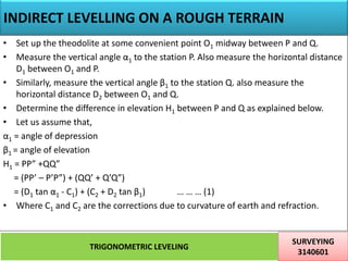
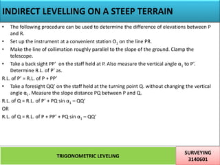
![Method of Observation
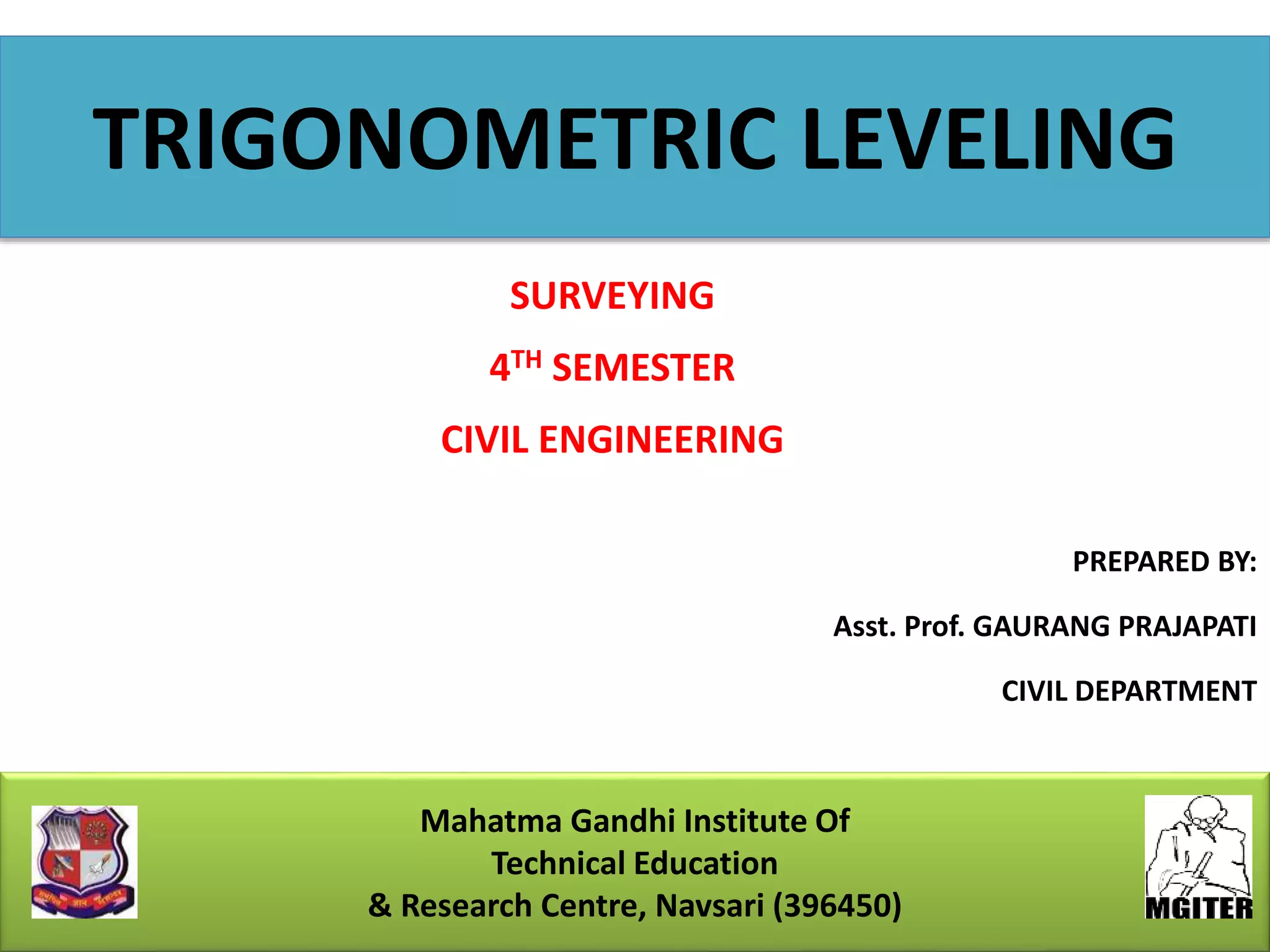
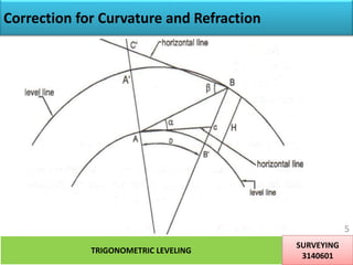
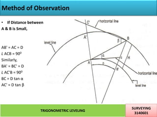
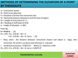
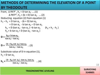
• If Distance between A & B is large,
• The correction for earth's curvature and refraction is required.
• Combined correction = 0.0673 D2, Where D = distance in KM.
• The difference in elevation between A & B,
H=BB'
=BC + CB'
=D tan α + 0.0673 D2. ....(1)
• If the angle of Depression B to A is measured,
AC'=D tan β [ BC'= D ]
• True difference in elevation between A & B,
H=AA'
= AC’ – A’C’
=D tan β - 0.0673 D2 ....(2)
TRIGONOMETRIC LEVELING
SURVEYING
3140601
7](https://image.slidesharecdn.com/trigonometriclevelling-200516082913/85/Trigonometric-levelling-7-320.jpg)
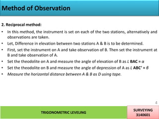
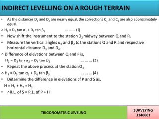
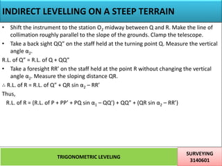
![Method of Observation
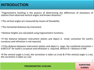
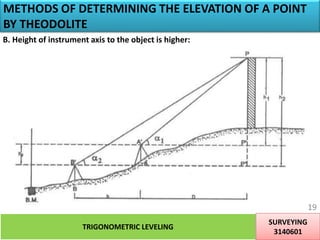
• Adding equation (1) & (2),
2 H = D tan α + D tan β
H = D/2 [tan α + D tan β] ..... (3)
• From equation (3), it can be seen that by reciprocal method of observation, the
correction for earth’s curvature and refraction can be eliminated.
R.L of station B = R.L. of station A + H
= R.L. of station A + D/2 [tan α + D tan β]
TRIGONOMETRIC LEVELING
SURVEYING
3140601
8](https://image.slidesharecdn.com/trigonometriclevelling-200516082913/85/Trigonometric-levelling-8-320.jpg)
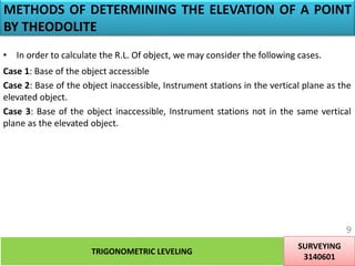
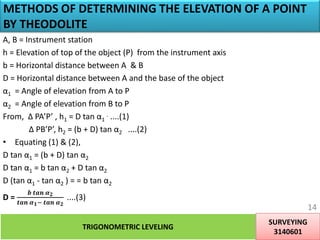
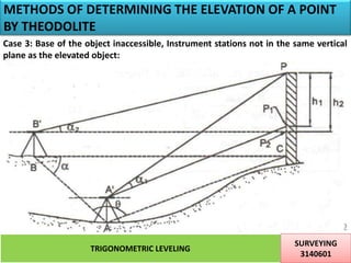
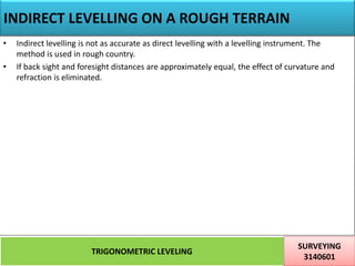
![METHODS OF DETERMINING THE ELEVATION OF A POINT
BY THEODOLITE
TRIGONOMETRIC LEVELING
SURVEYING
3140601
25
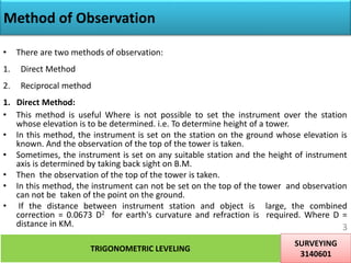
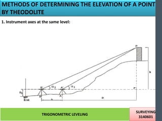
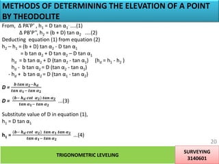
We know, three angles and one side of Δ ABC. Therefore using Sine Rule, we can calculate distance AC & BC
as below.
BC =
𝒃 𝒔𝒊𝒏 𝜽
𝐬𝐢𝐧 [𝟏𝟖𝟎− 𝜽+𝛂 ]
……(1)
Ac =
𝒃 𝒔𝒊𝒏 𝜶
𝐬𝐢𝐧 [𝟏𝟖𝟎− 𝜽+𝛂 ]
……(2)
Now, h1= AC tan α1 & h2= BC tan α2
Values of AC & BC are obtained from equation (1) & (2) as above.
R.L. of P = Height of instrument axis at A + h1 OR R.L. of P = Height of instrument axis at B + h2
Height of instrument axis at A,
= R.L. of B.M. + B.S.
= R.L. of B.M. + hs
Height of instrument axis at B = R.L. of B.M. + B.S.](https://image.slidesharecdn.com/trigonometriclevelling-200516082913/85/Trigonometric-levelling-25-320.jpg)


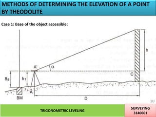
This document describes methods of trigonometric leveling to determine the elevation of points. It discusses using a theodolite to measure vertical angles and calculate heights based on trigonometric functions. The key methods covered are: 1. Direct and reciprocal methods of observation between two stations to eliminate corrections. 2. Determining heights when the base is accessible or inaccessible using one or two instrument stations, applying corrections for curvature and refraction based on distance. 3. Calculating heights when instrument stations are at different elevations, providing equations to solve for distance and elevation.


