Downloaded 24 times


![Experiment No- 4 [A]
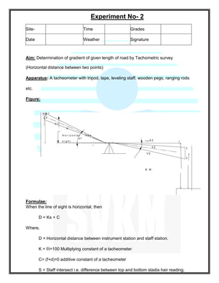
Aim:
To set out the simple curve by Rankin’s method of Deflection angles by using Single theodolite method.
Instruments required:
Theodolite, Ranging rods, Chain, Arrows and pegs.
Principle:
The deflection angle to any point on a circular curve is measured by one – half the angle subtended by
the arc from point of curve to that point. It is assumed that the length of the arc is approximately equal to
its chord.
Given data:
Chainage of curve, angle of intersection () and radius of curve (R)
Procedure:
Site- Time Grades
Date Weather Signature](https://image.slidesharecdn.com/laboratorymanualsurveyingii-200202155933/85/Laboratory-manual-surveying_ii-21-320.jpg)


![Experiment No- 4 [B]
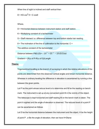
Aim:
To set out the transition curve combined with the circular curve by method of deflection angles.
Instruments required:
Theodolite, Ranging rods, Tape or Chain and accessories.
Transition curve:
A transition curve or easement curve is a curve of varying radius introduced between a straight and a
circular curve, or between two branches of a compound curve.
Ideal Transition curve:
The fundamental requirement of a transition curve is that its radius of curvature ‘r’ at any point shall vary
inversely as the distance (l) from the beginning of the curve. Such a curve is the clothed or the Glover’s
spiral and is known as the ideal transition curve.
Procedure:
In order to make the computations for various quantities of the transition and circular curve the data
necessary are
1. The deflection angle () between the original tangents
2. The Radius of the circular curve ( R )
3. The Length of the transition curve (L)
4. The point of intersection (V).
Site- Time Grades
Date Weather Signature](https://image.slidesharecdn.com/laboratorymanualsurveyingii-200202155933/85/Laboratory-manual-surveying_ii-24-320.jpg)


The laboratory manual outlines experiments for determining the multiplying and additive constants of a tacheometer for surveying applications. It includes methodologies for calculating distances using horizontal and inclined lines of sight, as well as procedures for experiments focused on gradient determination and curve setting. Additionally, it covers the use of aerial photographs for stereoscopic viewing, providing techniques and formulae relevant to tacheometry and surveying principles.


![3314493 [Autosaved].ppts survey methods@](https://cdn.slidesharecdn.com/ss_thumbnails/3314493autosaved-250203063339-98d1f88d-thumbnail.jpg?width=640&height=640&fit=bounds)


