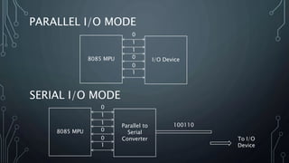
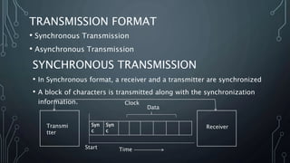
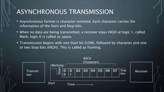
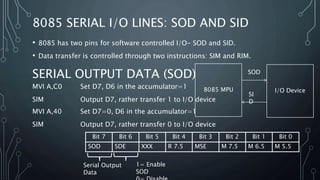
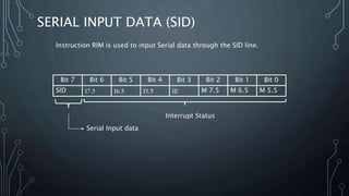
MICROPROCESSOR 8085
LECTURE 26
SERIAL AND PARALLEL DATA TRANSFER
PROF. SANDIP DAS
PARALLEL I/O MODE
8085 MPU I/O Device
0
1
1
0
0
1
SERIAL I/O MODE
8085 MPU
Parallel to
Serial
Converter
0
1
1
0
0
1
100110
To I/O
Device
SERIAL I/O MODE
The basic concepts concerning the Serial mode can be classified
into the following:
• Interfacing requirements
• Alphanumeric codes
• Transmission format
• Error checks in Data Communication
• Standards in Serial I/O
• Software vs Programmable Hardware approaches
INTERFACING REQUIREMENTS
8085 MPU Serial
Peripheral
Trans
mitReceiv
e
𝐼𝑂𝑊
𝐼𝑂𝑅
• The microprocessor identifies the peripheral through
a port address and enables it using the Read or Write
control signal.
• The primary difference between parallel I/O and
Serial I/O is in the number of lines used for data
transfer-Parallel I/O uses the entire data bus and
Serial I/O uses one data line.
TRANSMISSION FORMAT
• Synchronous Transmission
• Asynchronous Transmission
SYNCHRONOUS TRANSMISSION
• In Synchronous format, a receiver and a transmitter are synchronized
• A block of characters is transmitted along with the synchronization
information.
Syn
c
Syn
c
Data
TimeStart
Transmi
tter
Receiver
Clock
ASYNCHRONOUS TRANSMISSION
• Asynchronous format is character oriented. Each character carries the
information of the Start and Stop bits.
• When no data are being transmitted, a receiver stays HIGH at logic 1, called
Mark; logic 0 is called as space.
• Transmission begins with one Start bit (LOW), followed by character and one
or two Stop bits (HIGH). This is called as framing.
D
0
D
1
D2 D3 D4 D5 D6 D7
TimeStart
Transmi
tter
Receiver
Start
Stop
bits
Marking
ASCII
Characters
8085 SERIAL I/O LINES: SOD AND SID
• 8085 has two pins for software controlled I/O- SOD and SID.
• Data transfer is controlled through two instructions: SIM and RIM.
SERIAL OUTPUT DATA (SOD)
MVI A,C0 Set D7, D6 in the accumulator=1
SIM Output D7, rather transfer 1 to I/O device
Bit 7 Bit 6 Bit 5 Bit 4 Bit 3 Bit 2 Bit 1 Bit 0
SOD SDE XXX R 7.5 MSE M 7.5 M 6.5 M 5.5
1= Enable
SOD
Serial Output
Data
8085 MPU I/O Device
SOD
SI
D
MVI A,40 Set D7=0, D6 in the accumulator=1
SIM Output D7, rather transfer 0 to I/O device
SERIAL INPUT DATA (SID)
Bit 7 Bit 6 Bit 5 Bit 4 Bit 3 Bit 2 Bit 1 Bit 0
SID I7.5 I6.5 I5.5 IE M 7.5 M 6.5 M 5.5
Serial Input data
Interrupt Status
Instruction RIM is used to input Serial data through the SID line.

23. serial and parallel data communication

  • 1.
    MICROPROCESSOR 8085 LECTURE 26 SERIALAND PARALLEL DATA TRANSFER PROF. SANDIP DAS
  • 2.
    PARALLEL I/O MODE 8085MPU I/O Device 0 1 1 0 0 1 SERIAL I/O MODE 8085 MPU Parallel to Serial Converter 0 1 1 0 0 1 100110 To I/O Device
  • 3.
    SERIAL I/O MODE Thebasic concepts concerning the Serial mode can be classified into the following: • Interfacing requirements • Alphanumeric codes • Transmission format • Error checks in Data Communication • Standards in Serial I/O • Software vs Programmable Hardware approaches
  • 4.
    INTERFACING REQUIREMENTS 8085 MPUSerial Peripheral Trans mitReceiv e 𝐼𝑂𝑊 𝐼𝑂𝑅 • The microprocessor identifies the peripheral through a port address and enables it using the Read or Write control signal. • The primary difference between parallel I/O and Serial I/O is in the number of lines used for data transfer-Parallel I/O uses the entire data bus and Serial I/O uses one data line.
  • 5.
    TRANSMISSION FORMAT • SynchronousTransmission • Asynchronous Transmission SYNCHRONOUS TRANSMISSION • In Synchronous format, a receiver and a transmitter are synchronized • A block of characters is transmitted along with the synchronization information. Syn c Syn c Data TimeStart Transmi tter Receiver Clock
  • 6.
    ASYNCHRONOUS TRANSMISSION • Asynchronousformat is character oriented. Each character carries the information of the Start and Stop bits. • When no data are being transmitted, a receiver stays HIGH at logic 1, called Mark; logic 0 is called as space. • Transmission begins with one Start bit (LOW), followed by character and one or two Stop bits (HIGH). This is called as framing. D 0 D 1 D2 D3 D4 D5 D6 D7 TimeStart Transmi tter Receiver Start Stop bits Marking ASCII Characters
  • 7.
    8085 SERIAL I/OLINES: SOD AND SID • 8085 has two pins for software controlled I/O- SOD and SID. • Data transfer is controlled through two instructions: SIM and RIM. SERIAL OUTPUT DATA (SOD) MVI A,C0 Set D7, D6 in the accumulator=1 SIM Output D7, rather transfer 1 to I/O device Bit 7 Bit 6 Bit 5 Bit 4 Bit 3 Bit 2 Bit 1 Bit 0 SOD SDE XXX R 7.5 MSE M 7.5 M 6.5 M 5.5 1= Enable SOD Serial Output Data 8085 MPU I/O Device SOD SI D MVI A,40 Set D7=0, D6 in the accumulator=1 SIM Output D7, rather transfer 0 to I/O device
  • 8.
    SERIAL INPUT DATA(SID) Bit 7 Bit 6 Bit 5 Bit 4 Bit 3 Bit 2 Bit 1 Bit 0 SID I7.5 I6.5 I5.5 IE M 7.5 M 6.5 M 5.5 Serial Input data Interrupt Status Instruction RIM is used to input Serial data through the SID line.