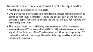
This document discusses input/output (I/O), communication devices, and interrupt service mechanisms. It covers various types of I/O such as serial and parallel ports and devices. It describes synchronous and asynchronous communication as well as protocols like UART, RS-232, RS-485, HDLC, and SPI. The document also discusses interrupt-driven I/O and the interrupt service mechanism, including interrupt sources, service routines, and context switching. Finally, it briefly mentions direct memory access and device driver programming.


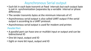
![PORT:
1. Device to receive the bytes from external
peripherals [or device(s) or processor(s) or
controllers] for reading them later using instructions
executed on the processor .
2. Device to send the bytes to external peripheral or
device or processor using instructions executed on
processor](https://image.slidesharecdn.com/esunit3-221026051825-4fb2eb51/85/ES-UNIT3-pptx-4-320.jpg)
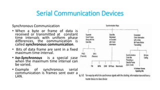
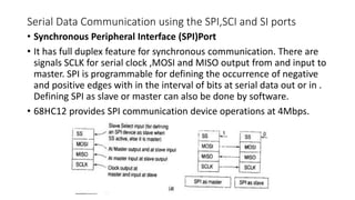
![Synchronous serial input
The sender along with the serial bits also
sends the clock pulses SCLK (serial
clock) to the receiver port pin. The port
synchronizes the serial data- input bits
with clock bits. Each bit in each byte as
well as each byte in synchronization
Synchronization means separation by a
constant interval or phase difference. If
clock period = T, then each byte at the
port is received at input in period = 8T.
The bytes are received at constant rates.
Each byte at input port separates by 8T
and data transfer rate for the serial line
bits is (1/T) bps. [1bps = 1 bit per sec]](https://image.slidesharecdn.com/esunit3-221026051825-4fb2eb51/85/ES-UNIT3-pptx-5-320.jpg)