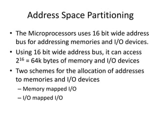
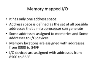
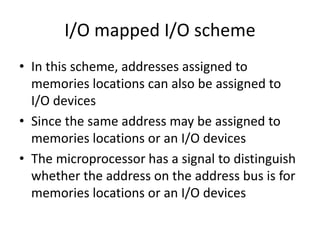
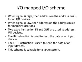
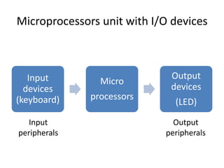
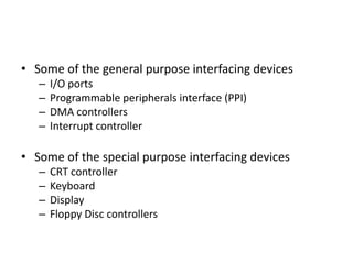
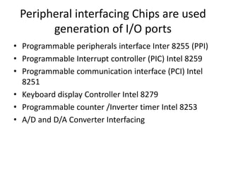
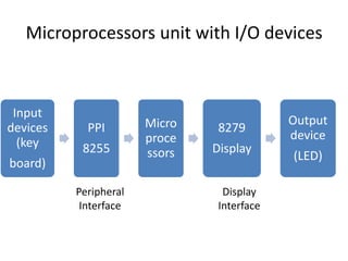
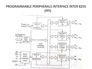
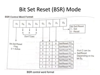
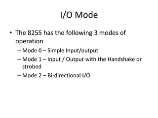
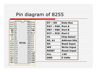
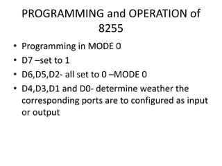
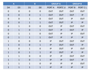
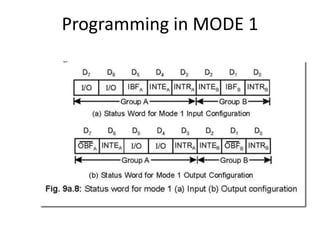
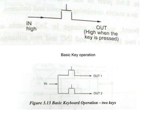
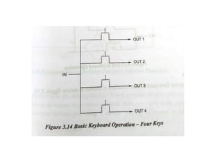
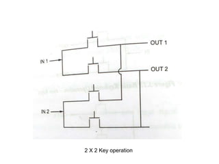
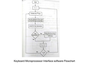
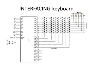
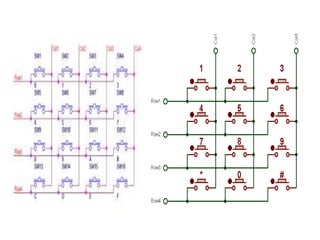
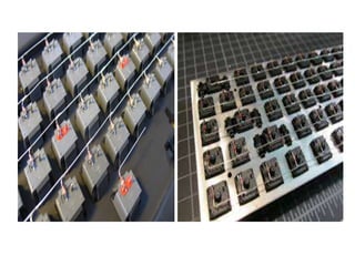
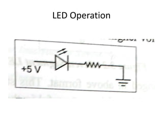
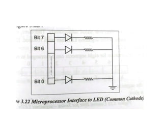
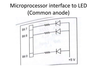
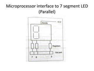
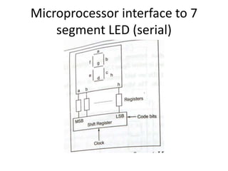
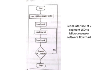
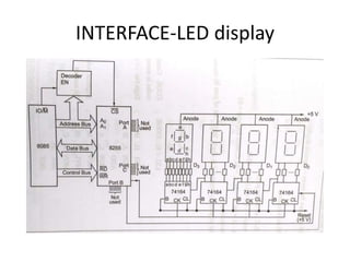
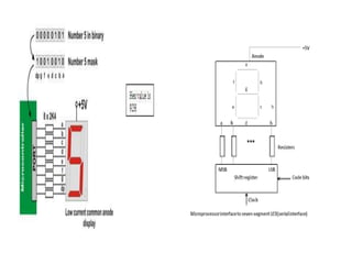
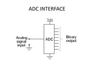
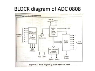
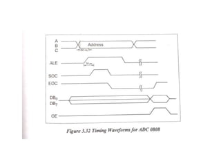
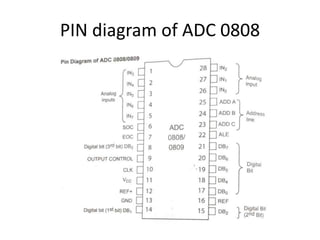
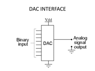
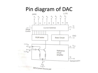
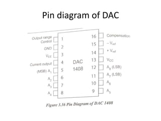
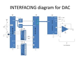
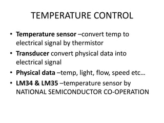
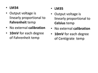
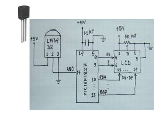
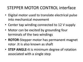
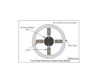
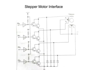
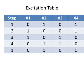
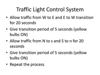
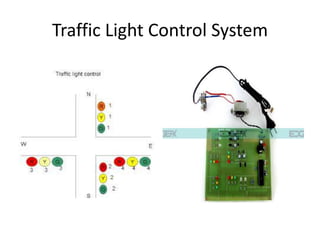
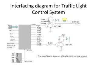
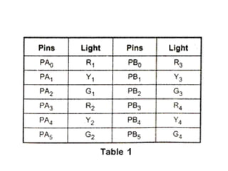
SlideShare a Scribd company logo
UNIT 3
PROGRAMMABLE PERIPERAL
INTERFACE
Content
• Introduction
• Architecture of 8255
• Keyboard interfacing
• LED display –interfacing
• ADC and DAC interface
• Temperature Control
• Stepper Motor Control
• Traffic Control interface
Introduction
• To communicate with the outside world,
microprocessor use peripherals (I/O devices)
• Input devices – Keyboards, A/D converters
etc.,
• Output devices – CRT, Printers, LEDs etc.,
• Peripherals are connected to the
microprocessors through electronic circuit
known as interfacing circuits.
Microprocessors unit with I/O devices
Input
devices
(keyboard)
Micro
processors
Output
devices
(LED)
Input
peripherals
Output
peripherals
• Some of the general purpose interfacing devices
– I/O ports
– Programmable peripherals interface (PPI)
– DMA controllers
– Interrupt controller
• Some of the special purpose interfacing devices
– CRT controller
– Keyboard
– Display
– Floppy Disc controllers
Peripheral interfacing Chips are used
generation of I/O ports
• Programmable peripherals interface Inter 8255 (PPI)
• Programmable Interrupt controller (PIC) Intel 8259
• Programmable communication interface (PCI) Intel
8251
• Keyboard display Controller Intel 8279
• Programmable counter /Inverter timer Intel 8253
• A/D and D/A Converter Interfacing
Microprocessors unit with I/O devices
Input
devices
(key
board)
PPI
8255
Micro
proce
ssors
8279
Display
Output
device
(LED)
Peripheral
Interface
Display
Interface
Address Space Partitioning
• The Microprocessors uses 16 bit wide address
bus for addressing memories and I/O devices.
• Using 16 bit wide address bus, it can access
216 = 64k bytes of memory and I/O devices
• Two schemes for the allocation of addresses
to memories and I/O devices
– Memory mapped I/O
– I/O mapped I/O
Memory mapped I/O
• It has only one address space
• Address space is defined as the set of all possible
addresses that a microprocessor can generate
• Some addresses assigned to memories and Some
addresses to I/O devices
• Memory locations are assigned with addresses
from 8000 to 84FF
• I/O devices are assigned with addresses from
8500 to 85FF
I/O mapped I/O scheme
• In this scheme, addresses assigned to
memories locations can also be assigned to
I/O devices
• Since the same address may be assigned to
memories locations or an I/O devices
• The microprocessor has a signal to distinguish
whether the address on the address bus is for
memories locations or an I/O devices
I/O mapped I/O scheme
• When signal is high, then address on the address bus is
for an I/O devices
• When signal is low, then address on the address bus is
for memory locations
• Two extra instruction IN and OUT are used to address
I/O devices.
• The IN instruction is used to read the data of an input
devices.
• The OUT instruction is used to send the data of an
input devices.
• This scheme is suitable for a large system.
PROGRAMMABLE PERIPHERALS INTERFACE INTER 8255
(PPI)
Operating mode of 8255
• Bit Set Reset (BSR) Mode
• I/O Mode
Bit Set Reset (BSR) Mode
BSR control word format
I/O Mode
• The 8255 has the following 3 modes of
operation
– Mode 0 – Simple Input/output
– Mode 1 – Input / Output with the Handshake or
strobed
– Mode 2 – Bi-directional I/O
I/O Mode
Mode 0 – Simple Input/output
– Port A and port B are used as two simple 8-bit I/O
port
– Port C as two 4-bit port
• Features
– Outputs are latched
– Inputs are buffered not latched
– Ports do not have handshake or interrupt
capability
I/O Mode
• Mode 1 – Input / Output with the Handshake
– Input or output data transfer is controlled by
handshaking signals.
– Handshaking signals are used to transfer data
between devices whose data transfer speeds are
not same.
– Port A and Port B are designed to operate with the
Port C.
– When Port A and Port B are programmed in Mode
1, 6 pins of port C is used for their control.
I/O Mode
• D0-D7 data bus
– bi directional, tri state data bus line
– It is used to transfer data and control word from
8085 to 8255
• RD (Read)
– When this pin is low, the CPU can read data in the
port or status word through the data buffer
• WR (write)
– When this pin is low, the CPU can write data in the
port or in the control register through the data
buffer
I/O Mode
• Mode 2 – Bi-directional I/O
• Port A can be programmed to operate as a
bidirectional port.
• The mode 2 operation is only for port A
• When port A is programmed in Mode 2, the
Port B can be used in either Mode 1 or Mode
0.
• Mode 2 operation the port a is controlled by
PC3 to PC7 of port C.
PIN
DIAGRAM
OF 8255
PROGRAMMING and OPERATION of
8255
• Programming in MODE 0
• D7 –set to 1
• D6,D5,D2- all set to 0 –MODE 0
• D4,D3,D1 and D0- determine weather the
corresponding ports are to configured as input
or output
A B GROUP A GROUP B
D4 D3 D1 D0 PORT A PORTC U PORT B PORT C L
0 0 0 0 OUT OUT OUT OUT
0 0 0 1 OUT OUT OUT IP
0 0 1 0 OUT OUT IP OUT
0 0 1 1 OUT OUT IP IP
0 1 0 0 OUT IP OUT OUT
0 1 0 1 OUT IP OUT IP
0 1 1 0 OUT IP IP OUT
0 1 1 1 OUT IP IP IP
1 0 0 0 IP OUT OUT OUT
1 0 0 1 IP OUT OUT IP
1 0 1 0 IP OUT IP OUT
1 0 1 1 IP OUT IP IP
1 1 0 0 IP IP OUT OUT
1 1 0 1 IP IP OUT IP
1 1 1 0 IP IP IP OUT
1 1 1 1 IP IP IP IP
Programming in MODE 1
• IBF- input buffer full
• INTR- interrupt request
• INTE-interrupt enable
• OBF-output buffer full
• INTR-interrupt request
• INTE-interrupt enable
Programming in MODE 2
Interfacing cable
Basic Key operation
2 X 2 Key operation
Keyboard Microprocessor Interface software Flowchart
INTERFACING-keyboard
LED Operation
Microprocessor interface to LED
(Common anode)
Microprocessor interface to 7 segment LED
(Parallel)
Microprocessor interface to 7
segment LED (serial)
Serial interface of 7
segment LED to
Microprocessor
software flowchart
INTERFACE-LED display
ADC INTERFACE
BLOCK diagram of ADC 0808
PIN diagram of ADC 0808
DAC INTERFACE
Pin diagram of DAC
Pin diagram of DAC
INTERFACING diagram for DAC
TEMPERATURE CONTROL
• Temperature sensor –convert temp to
electrical signal by thermistor
• Transducer convert physical data into
electrical signal
• Physical data –temp, light, flow, speed etc…
• LM34 & LM35 –temperature sensor by
NATIONAL SEMICONDUCTOR CO-OPERATION
• LM34
• Output voltage is
linearly proportional to
Fahrenheit temp
• No external calibration
• 10mV for each degree
of Fahrenheit temp
• LM35
• Output voltage is
linearly proportional to
Celsius temp
• No external calibration
• 10mV for each degree
of Centigrate temp
STEPPER MOTOR CONTROL interface
• Digital motor used to translate electrical pulse
into mechanical movement
• Center tap winding connected to 12 V supply
• Motor can be excited by grounding four
terminals of the two windings
• ROTOR-Stepper motor has permanent magnet
rotor .It is also known as shaft
• STEP ANGLE-It is minimum degree of rotation
associated with a single step
Stepper Motor Interface
Excitation Table
Step X1 X2 X3 X4
1 0 1 0 1
2 1 0 0 1
3 1 0 1 0
4 0 1 1 0
1 0 1 0 1
Traffic Light Control System
• Allow traffic from W to E and E to W transition
for 20 seconds
• Give transition period of 5 seconds (yellow
bulbs ON)
• Allow traffic from N to s and S to n for 20
seconds
• Give transition period of 5 seconds (yellow
bulbs ON)
• Repeat the process
Traffic Light Control System
Interfacing diagram for Traffic Light
Control System
20ME702– MECHATRONICS -UNIT-3.ppt

More Related Content

Similar to 20ME702– MECHATRONICS -UNIT-3.ppt

MPMC
MPMC MPMC
8255 ppi students material for ppi mpmc study
8255 ppi students material for ppi mpmc study8255 ppi students material for ppi mpmc study
8255 ppi students material for ppi mpmc study
Sirisha Vamsi
 
Interfacing with peripherals: analog to digital converters and digital to ana...
Interfacing with peripherals: analog to digital converters and digital to ana...Interfacing with peripherals: analog to digital converters and digital to ana...
Interfacing with peripherals: analog to digital converters and digital to ana...
NimeshSingh27
 
Parth xyz
Parth xyzParth xyz
Parth xyz
ParthBabariya15
 
8255 PPI.pptx
8255 PPI.pptx8255 PPI.pptx
8255 PPI.pptx
ssuser823c58
 
23. serial and parallel data communication
23. serial and parallel data communication23. serial and parallel data communication
23. serial and parallel data communication
sandip das
 
8251 -USART.pptx
8251 -USART.pptx8251 -USART.pptx
8251 -USART.pptx
VikasMahor3
 
20620115-Programmable-Logic-Controllers.ppt
20620115-Programmable-Logic-Controllers.ppt20620115-Programmable-Logic-Controllers.ppt
20620115-Programmable-Logic-Controllers.ppt
mohammedsaadqureshi
 
INTRODUCTION TO MICROCONTROLLER
INTRODUCTION TO MICROCONTROLLERINTRODUCTION TO MICROCONTROLLER
INTRODUCTION TO MICROCONTROLLER
Ankita Jaiswal
 
Uc1(vii sem)
Uc1(vii sem)Uc1(vii sem)
Uc1(vii sem)
Ankita Jaiswal
 
Micro Processor And Micro Controller for engineering in Pondicherry University
Micro Processor And Micro Controller for engineering in Pondicherry UniversityMicro Processor And Micro Controller for engineering in Pondicherry University
Micro Processor And Micro Controller for engineering in Pondicherry University
ShyamShyam76
 
20ME702– MECHATRONICS -UNIT-4.ppt
20ME702– MECHATRONICS -UNIT-4.ppt20ME702– MECHATRONICS -UNIT-4.ppt
20ME702– MECHATRONICS -UNIT-4.ppt
Mohanumar S
 
Programmable logic Controlller ppt
Programmable logic Controlller pptProgrammable logic Controlller ppt
Programmable logic Controlller ppt
karthik R
 
Unit 4-PROGRAMMABLE LOGIC INTERFACE-ME6702– MECHATRONICS
Unit 4-PROGRAMMABLE LOGIC INTERFACE-ME6702– MECHATRONICS Unit 4-PROGRAMMABLE LOGIC INTERFACE-ME6702– MECHATRONICS
Unit 4-PROGRAMMABLE LOGIC INTERFACE-ME6702– MECHATRONICS
Mohanumar S
 
Unit 3 mpmc
Unit 3 mpmcUnit 3 mpmc
Unit 3 mpmc
tamilnesaner
 
UNIT 4 8051Microcontroller.pptx
UNIT 4 8051Microcontroller.pptxUNIT 4 8051Microcontroller.pptx
UNIT 4 8051Microcontroller.pptx
Gowrishankar C
 
Peripherals and interfacing
Peripherals  and interfacingPeripherals  and interfacing
Peripherals and interfacing
RAMPRAKASHT1
 
8255-PPI MPMC text book for engineering.ppt
8255-PPI MPMC text book for engineering.ppt8255-PPI MPMC text book for engineering.ppt
8255-PPI MPMC text book for engineering.ppt
khushiduppala
 

Similar to 20ME702– MECHATRONICS -UNIT-3.ppt (20)

MPMC
MPMC MPMC
MPMC
 
8255 ppi students material for ppi mpmc study
8255 ppi students material for ppi mpmc study8255 ppi students material for ppi mpmc study
8255 ppi students material for ppi mpmc study
 
Interfacing with peripherals: analog to digital converters and digital to ana...
Interfacing with peripherals: analog to digital converters and digital to ana...Interfacing with peripherals: analog to digital converters and digital to ana...
Interfacing with peripherals: analog to digital converters and digital to ana...
 
Wds
WdsWds
Wds
 
Parth xyz
Parth xyzParth xyz
Parth xyz
 
Arduino
ArduinoArduino
Arduino
 
8255 PPI.pptx
8255 PPI.pptx8255 PPI.pptx
8255 PPI.pptx
 
23. serial and parallel data communication
23. serial and parallel data communication23. serial and parallel data communication
23. serial and parallel data communication
 
8251 -USART.pptx
8251 -USART.pptx8251 -USART.pptx
8251 -USART.pptx
 
20620115-Programmable-Logic-Controllers.ppt
20620115-Programmable-Logic-Controllers.ppt20620115-Programmable-Logic-Controllers.ppt
20620115-Programmable-Logic-Controllers.ppt
 
INTRODUCTION TO MICROCONTROLLER
INTRODUCTION TO MICROCONTROLLERINTRODUCTION TO MICROCONTROLLER
INTRODUCTION TO MICROCONTROLLER
 
Uc1(vii sem)
Uc1(vii sem)Uc1(vii sem)
Uc1(vii sem)
 
Micro Processor And Micro Controller for engineering in Pondicherry University
Micro Processor And Micro Controller for engineering in Pondicherry UniversityMicro Processor And Micro Controller for engineering in Pondicherry University
Micro Processor And Micro Controller for engineering in Pondicherry University
 
20ME702– MECHATRONICS -UNIT-4.ppt
20ME702– MECHATRONICS -UNIT-4.ppt20ME702– MECHATRONICS -UNIT-4.ppt
20ME702– MECHATRONICS -UNIT-4.ppt
 
Programmable logic Controlller ppt
Programmable logic Controlller pptProgrammable logic Controlller ppt
Programmable logic Controlller ppt
 
Unit 4-PROGRAMMABLE LOGIC INTERFACE-ME6702– MECHATRONICS
Unit 4-PROGRAMMABLE LOGIC INTERFACE-ME6702– MECHATRONICS Unit 4-PROGRAMMABLE LOGIC INTERFACE-ME6702– MECHATRONICS
Unit 4-PROGRAMMABLE LOGIC INTERFACE-ME6702– MECHATRONICS
 
Unit 3 mpmc
Unit 3 mpmcUnit 3 mpmc
Unit 3 mpmc
 
UNIT 4 8051Microcontroller.pptx
UNIT 4 8051Microcontroller.pptxUNIT 4 8051Microcontroller.pptx
UNIT 4 8051Microcontroller.pptx
 
Peripherals and interfacing
Peripherals  and interfacingPeripherals  and interfacing
Peripherals and interfacing
 
8255-PPI MPMC text book for engineering.ppt
8255-PPI MPMC text book for engineering.ppt8255-PPI MPMC text book for engineering.ppt
8255-PPI MPMC text book for engineering.ppt
 

More from Mohanumar S

20CE501PE – INDUSTRIAL WASTE MANAGEMENT.ppt
20CE501PE – INDUSTRIAL WASTE MANAGEMENT.ppt20CE501PE – INDUSTRIAL WASTE MANAGEMENT.ppt
20CE501PE – INDUSTRIAL WASTE MANAGEMENT.ppt
Mohanumar S
 
20ME702– MECHATRONICS -UNIT-2.pptx
20ME702– MECHATRONICS -UNIT-2.pptx20ME702– MECHATRONICS -UNIT-2.pptx
20ME702– MECHATRONICS -UNIT-2.pptx
Mohanumar S
 
20ME702– MECHATRONICS -UNIT-5-Motor.ppt
20ME702– MECHATRONICS -UNIT-5-Motor.ppt20ME702– MECHATRONICS -UNIT-5-Motor.ppt
20ME702– MECHATRONICS -UNIT-5-Motor.ppt
Mohanumar S
 
20ME702– MECHATRONICS -UNIT-1-Sensor and transducers.ppt
20ME702– MECHATRONICS -UNIT-1-Sensor and transducers.ppt20ME702– MECHATRONICS -UNIT-1-Sensor and transducers.ppt
20ME702– MECHATRONICS -UNIT-1-Sensor and transducers.ppt
Mohanumar S
 
M.P- II-UNIT II CENTRE LATHE AND SPECIAL PURPOSE LATHES..ppt
M.P- II-UNIT II  CENTRE LATHE AND SPECIAL PURPOSE  LATHES..pptM.P- II-UNIT II  CENTRE LATHE AND SPECIAL PURPOSE  LATHES..ppt
M.P- II-UNIT II CENTRE LATHE AND SPECIAL PURPOSE LATHES..ppt
Mohanumar S
 
M.P- II-UNIT I -THEORY OF METAL CUTTING.ppt
M.P- II-UNIT I -THEORY OF METAL CUTTING.pptM.P- II-UNIT I -THEORY OF METAL CUTTING.ppt
M.P- II-UNIT I -THEORY OF METAL CUTTING.ppt
Mohanumar S
 
M.P- II-UNIT III-SHAPER, MILLING AND BROACHING MACHINES.ppt
M.P- II-UNIT III-SHAPER, MILLING AND BROACHING MACHINES.pptM.P- II-UNIT III-SHAPER, MILLING AND BROACHING MACHINES.ppt
M.P- II-UNIT III-SHAPER, MILLING AND BROACHING MACHINES.ppt
Mohanumar S
 
M.P- II-UNIT IV - ABRASIVE PROCESSES AND GEAR CUTTING.pptx
M.P- II-UNIT IV - ABRASIVE PROCESSES AND GEAR CUTTING.pptxM.P- II-UNIT IV - ABRASIVE PROCESSES AND GEAR CUTTING.pptx
M.P- II-UNIT IV - ABRASIVE PROCESSES AND GEAR CUTTING.pptx
Mohanumar S
 
M.P- II-UNIT V - CNC MACHINE TOOLS AND PART PROGRAMMING.ppt
M.P- II-UNIT V - CNC MACHINE TOOLS AND PART PROGRAMMING.pptM.P- II-UNIT V - CNC MACHINE TOOLS AND PART PROGRAMMING.ppt
M.P- II-UNIT V - CNC MACHINE TOOLS AND PART PROGRAMMING.ppt
Mohanumar S
 
EM-Unit-V-Mechanical properties
EM-Unit-V-Mechanical propertiesEM-Unit-V-Mechanical properties
EM-Unit-V-Mechanical properties
Mohanumar S
 
EM-UNIT-V-Testing utm-hardness-impact
EM-UNIT-V-Testing  utm-hardness-impactEM-UNIT-V-Testing  utm-hardness-impact
EM-UNIT-V-Testing utm-hardness-impact
Mohanumar S
 
EM-Unit-IV- Vacuum plasma hardening
EM-Unit-IV- Vacuum plasma hardeningEM-Unit-IV- Vacuum plasma hardening
EM-Unit-IV- Vacuum plasma hardening
Mohanumar S
 
EM-Unit-IV- Ttt diagram
EM-Unit-IV- Ttt diagramEM-Unit-IV- Ttt diagram
EM-Unit-IV- Ttt diagram
Mohanumar S
 
EM-Unit-IV- Cct diagram
EM-Unit-IV- Cct diagramEM-Unit-IV- Cct diagram
EM-Unit-IV- Cct diagram
Mohanumar S
 
EM-Unit-IV- Case hardening
EM-Unit-IV- Case hardeningEM-Unit-IV- Case hardening
EM-Unit-IV- Case hardening
Mohanumar S
 
EM-Unit-IV- case hardening
EM-Unit-IV- case hardeningEM-Unit-IV- case hardening
EM-Unit-IV- case hardening
Mohanumar S
 
EM-Unit-IV- heat treatment
EM-Unit-IV- heat treatmentEM-Unit-IV- heat treatment
EM-Unit-IV- heat treatment
Mohanumar S
 
EM-UNIT III -ceramics & composites
EM-UNIT III -ceramics & compositesEM-UNIT III -ceramics & composites
EM-UNIT III -ceramics & composites
Mohanumar S
 
EM-UNIT III - thermoplastics prop and applications
EM-UNIT III - thermoplastics prop and applicationsEM-UNIT III - thermoplastics prop and applications
EM-UNIT III - thermoplastics prop and applications
Mohanumar S
 
EM-UNIT III -propertis and applications of thermoplastics
EM-UNIT III -propertis and applications of thermoplasticsEM-UNIT III -propertis and applications of thermoplastics
EM-UNIT III -propertis and applications of thermoplastics
Mohanumar S
 

More from Mohanumar S (20)

20CE501PE – INDUSTRIAL WASTE MANAGEMENT.ppt
20CE501PE – INDUSTRIAL WASTE MANAGEMENT.ppt20CE501PE – INDUSTRIAL WASTE MANAGEMENT.ppt
20CE501PE – INDUSTRIAL WASTE MANAGEMENT.ppt
 
20ME702– MECHATRONICS -UNIT-2.pptx
20ME702– MECHATRONICS -UNIT-2.pptx20ME702– MECHATRONICS -UNIT-2.pptx
20ME702– MECHATRONICS -UNIT-2.pptx
 
20ME702– MECHATRONICS -UNIT-5-Motor.ppt
20ME702– MECHATRONICS -UNIT-5-Motor.ppt20ME702– MECHATRONICS -UNIT-5-Motor.ppt
20ME702– MECHATRONICS -UNIT-5-Motor.ppt
 
20ME702– MECHATRONICS -UNIT-1-Sensor and transducers.ppt
20ME702– MECHATRONICS -UNIT-1-Sensor and transducers.ppt20ME702– MECHATRONICS -UNIT-1-Sensor and transducers.ppt
20ME702– MECHATRONICS -UNIT-1-Sensor and transducers.ppt
 
M.P- II-UNIT II CENTRE LATHE AND SPECIAL PURPOSE LATHES..ppt
M.P- II-UNIT II  CENTRE LATHE AND SPECIAL PURPOSE  LATHES..pptM.P- II-UNIT II  CENTRE LATHE AND SPECIAL PURPOSE  LATHES..ppt
M.P- II-UNIT II CENTRE LATHE AND SPECIAL PURPOSE LATHES..ppt
 
M.P- II-UNIT I -THEORY OF METAL CUTTING.ppt
M.P- II-UNIT I -THEORY OF METAL CUTTING.pptM.P- II-UNIT I -THEORY OF METAL CUTTING.ppt
M.P- II-UNIT I -THEORY OF METAL CUTTING.ppt
 
M.P- II-UNIT III-SHAPER, MILLING AND BROACHING MACHINES.ppt
M.P- II-UNIT III-SHAPER, MILLING AND BROACHING MACHINES.pptM.P- II-UNIT III-SHAPER, MILLING AND BROACHING MACHINES.ppt
M.P- II-UNIT III-SHAPER, MILLING AND BROACHING MACHINES.ppt
 
M.P- II-UNIT IV - ABRASIVE PROCESSES AND GEAR CUTTING.pptx
M.P- II-UNIT IV - ABRASIVE PROCESSES AND GEAR CUTTING.pptxM.P- II-UNIT IV - ABRASIVE PROCESSES AND GEAR CUTTING.pptx
M.P- II-UNIT IV - ABRASIVE PROCESSES AND GEAR CUTTING.pptx
 
M.P- II-UNIT V - CNC MACHINE TOOLS AND PART PROGRAMMING.ppt
M.P- II-UNIT V - CNC MACHINE TOOLS AND PART PROGRAMMING.pptM.P- II-UNIT V - CNC MACHINE TOOLS AND PART PROGRAMMING.ppt
M.P- II-UNIT V - CNC MACHINE TOOLS AND PART PROGRAMMING.ppt
 
EM-Unit-V-Mechanical properties
EM-Unit-V-Mechanical propertiesEM-Unit-V-Mechanical properties
EM-Unit-V-Mechanical properties
 
EM-UNIT-V-Testing utm-hardness-impact
EM-UNIT-V-Testing  utm-hardness-impactEM-UNIT-V-Testing  utm-hardness-impact
EM-UNIT-V-Testing utm-hardness-impact
 
EM-Unit-IV- Vacuum plasma hardening
EM-Unit-IV- Vacuum plasma hardeningEM-Unit-IV- Vacuum plasma hardening
EM-Unit-IV- Vacuum plasma hardening
 
EM-Unit-IV- Ttt diagram
EM-Unit-IV- Ttt diagramEM-Unit-IV- Ttt diagram
EM-Unit-IV- Ttt diagram
 
EM-Unit-IV- Cct diagram
EM-Unit-IV- Cct diagramEM-Unit-IV- Cct diagram
EM-Unit-IV- Cct diagram
 
EM-Unit-IV- Case hardening
EM-Unit-IV- Case hardeningEM-Unit-IV- Case hardening
EM-Unit-IV- Case hardening
 
EM-Unit-IV- case hardening
EM-Unit-IV- case hardeningEM-Unit-IV- case hardening
EM-Unit-IV- case hardening
 
EM-Unit-IV- heat treatment
EM-Unit-IV- heat treatmentEM-Unit-IV- heat treatment
EM-Unit-IV- heat treatment
 
EM-UNIT III -ceramics & composites
EM-UNIT III -ceramics & compositesEM-UNIT III -ceramics & composites
EM-UNIT III -ceramics & composites
 
EM-UNIT III - thermoplastics prop and applications
EM-UNIT III - thermoplastics prop and applicationsEM-UNIT III - thermoplastics prop and applications
EM-UNIT III - thermoplastics prop and applications
 
EM-UNIT III -propertis and applications of thermoplastics
EM-UNIT III -propertis and applications of thermoplasticsEM-UNIT III -propertis and applications of thermoplastics
EM-UNIT III -propertis and applications of thermoplastics
 

Recently uploaded

Standard Reomte Control Interface - Neometrix
Standard Reomte Control Interface - NeometrixStandard Reomte Control Interface - Neometrix
Standard Reomte Control Interface - Neometrix
Neometrix_Engineering_Pvt_Ltd
 
Water Industry Process Automation and Control Monthly - May 2024.pdf
Water Industry Process Automation and Control Monthly - May 2024.pdfWater Industry Process Automation and Control Monthly - May 2024.pdf
Water Industry Process Automation and Control Monthly - May 2024.pdf
Water Industry Process Automation & Control
 
H.Seo, ICLR 2024, MLILAB, KAIST AI.pdf
H.Seo,  ICLR 2024, MLILAB,  KAIST AI.pdfH.Seo,  ICLR 2024, MLILAB,  KAIST AI.pdf
H.Seo, ICLR 2024, MLILAB, KAIST AI.pdf
MLILAB
 
AKS UNIVERSITY Satna Final Year Project By OM Hardaha.pdf
AKS UNIVERSITY Satna Final Year Project By OM Hardaha.pdfAKS UNIVERSITY Satna Final Year Project By OM Hardaha.pdf
AKS UNIVERSITY Satna Final Year Project By OM Hardaha.pdf
SamSarthak3
 
LIGA(E)11111111111111111111111111111111111111111.ppt
LIGA(E)11111111111111111111111111111111111111111.pptLIGA(E)11111111111111111111111111111111111111111.ppt
LIGA(E)11111111111111111111111111111111111111111.ppt
ssuser9bd3ba
 
block diagram and signal flow graph representation
block diagram and signal flow graph representationblock diagram and signal flow graph representation
block diagram and signal flow graph representation
Divya Somashekar
 
Industrial Training at Shahjalal Fertilizer Company Limited (SFCL)
Industrial Training at Shahjalal Fertilizer Company Limited (SFCL)Industrial Training at Shahjalal Fertilizer Company Limited (SFCL)
Industrial Training at Shahjalal Fertilizer Company Limited (SFCL)
MdTanvirMahtab2
 
Democratizing Fuzzing at Scale by Abhishek Arya
Democratizing Fuzzing at Scale by Abhishek AryaDemocratizing Fuzzing at Scale by Abhishek Arya
Democratizing Fuzzing at Scale by Abhishek Arya
abh.arya
 
road safety engineering r s e unit 3.pdf
road safety engineering  r s e unit 3.pdfroad safety engineering  r s e unit 3.pdf
road safety engineering r s e unit 3.pdf
VENKATESHvenky89705
 
Gen AI Study Jams _ For the GDSC Leads in India.pdf
Gen AI Study Jams _ For the GDSC Leads in India.pdfGen AI Study Jams _ For the GDSC Leads in India.pdf
Gen AI Study Jams _ For the GDSC Leads in India.pdf
gdsczhcet
 
MCQ Soil mechanics questions (Soil shear strength).pdf
MCQ Soil mechanics questions (Soil shear strength).pdfMCQ Soil mechanics questions (Soil shear strength).pdf
MCQ Soil mechanics questions (Soil shear strength).pdf
Osamah Alsalih
 
WATER CRISIS and its solutions-pptx 1234
WATER CRISIS and its solutions-pptx 1234WATER CRISIS and its solutions-pptx 1234
WATER CRISIS and its solutions-pptx 1234
AafreenAbuthahir2
 
power quality voltage fluctuation UNIT - I.pptx
power quality voltage fluctuation UNIT - I.pptxpower quality voltage fluctuation UNIT - I.pptx
power quality voltage fluctuation UNIT - I.pptx
ViniHema
 
一比一原版(SFU毕业证)西蒙菲莎大学毕业证成绩单如何办理
一比一原版(SFU毕业证)西蒙菲莎大学毕业证成绩单如何办理一比一原版(SFU毕业证)西蒙菲莎大学毕业证成绩单如何办理
一比一原版(SFU毕业证)西蒙菲莎大学毕业证成绩单如何办理
bakpo1
 
Final project report on grocery store management system..pdf
Final project report on grocery store management system..pdfFinal project report on grocery store management system..pdf
Final project report on grocery store management system..pdf
Kamal Acharya
 
Immunizing Image Classifiers Against Localized Adversary Attacks
Immunizing Image Classifiers Against Localized Adversary AttacksImmunizing Image Classifiers Against Localized Adversary Attacks
Immunizing Image Classifiers Against Localized Adversary Attacks
gerogepatton
 
Railway Signalling Principles Edition 3.pdf
Railway Signalling Principles Edition 3.pdfRailway Signalling Principles Edition 3.pdf
Railway Signalling Principles Edition 3.pdf
TeeVichai
 
ASME IX(9) 2007 Full Version .pdf
ASME IX(9)  2007 Full Version       .pdfASME IX(9)  2007 Full Version       .pdf
ASME IX(9) 2007 Full Version .pdf
AhmedHussein950959
 
Sachpazis:Terzaghi Bearing Capacity Estimation in simple terms with Calculati...
Sachpazis:Terzaghi Bearing Capacity Estimation in simple terms with Calculati...Sachpazis:Terzaghi Bearing Capacity Estimation in simple terms with Calculati...
Sachpazis:Terzaghi Bearing Capacity Estimation in simple terms with Calculati...
Dr.Costas Sachpazis
 
DESIGN A COTTON SEED SEPARATION MACHINE.docx
DESIGN A COTTON SEED SEPARATION MACHINE.docxDESIGN A COTTON SEED SEPARATION MACHINE.docx
DESIGN A COTTON SEED SEPARATION MACHINE.docx
FluxPrime1
 

Recently uploaded (20)

Standard Reomte Control Interface - Neometrix
Standard Reomte Control Interface - NeometrixStandard Reomte Control Interface - Neometrix
Standard Reomte Control Interface - Neometrix
 
Water Industry Process Automation and Control Monthly - May 2024.pdf
Water Industry Process Automation and Control Monthly - May 2024.pdfWater Industry Process Automation and Control Monthly - May 2024.pdf
Water Industry Process Automation and Control Monthly - May 2024.pdf
 
H.Seo, ICLR 2024, MLILAB, KAIST AI.pdf
H.Seo,  ICLR 2024, MLILAB,  KAIST AI.pdfH.Seo,  ICLR 2024, MLILAB,  KAIST AI.pdf
H.Seo, ICLR 2024, MLILAB, KAIST AI.pdf
 
AKS UNIVERSITY Satna Final Year Project By OM Hardaha.pdf
AKS UNIVERSITY Satna Final Year Project By OM Hardaha.pdfAKS UNIVERSITY Satna Final Year Project By OM Hardaha.pdf
AKS UNIVERSITY Satna Final Year Project By OM Hardaha.pdf
 
LIGA(E)11111111111111111111111111111111111111111.ppt
LIGA(E)11111111111111111111111111111111111111111.pptLIGA(E)11111111111111111111111111111111111111111.ppt
LIGA(E)11111111111111111111111111111111111111111.ppt
 
block diagram and signal flow graph representation
block diagram and signal flow graph representationblock diagram and signal flow graph representation
block diagram and signal flow graph representation
 
Industrial Training at Shahjalal Fertilizer Company Limited (SFCL)
Industrial Training at Shahjalal Fertilizer Company Limited (SFCL)Industrial Training at Shahjalal Fertilizer Company Limited (SFCL)
Industrial Training at Shahjalal Fertilizer Company Limited (SFCL)
 
Democratizing Fuzzing at Scale by Abhishek Arya
Democratizing Fuzzing at Scale by Abhishek AryaDemocratizing Fuzzing at Scale by Abhishek Arya
Democratizing Fuzzing at Scale by Abhishek Arya
 
road safety engineering r s e unit 3.pdf
road safety engineering  r s e unit 3.pdfroad safety engineering  r s e unit 3.pdf
road safety engineering r s e unit 3.pdf
 
Gen AI Study Jams _ For the GDSC Leads in India.pdf
Gen AI Study Jams _ For the GDSC Leads in India.pdfGen AI Study Jams _ For the GDSC Leads in India.pdf
Gen AI Study Jams _ For the GDSC Leads in India.pdf
 
MCQ Soil mechanics questions (Soil shear strength).pdf
MCQ Soil mechanics questions (Soil shear strength).pdfMCQ Soil mechanics questions (Soil shear strength).pdf
MCQ Soil mechanics questions (Soil shear strength).pdf
 
WATER CRISIS and its solutions-pptx 1234
WATER CRISIS and its solutions-pptx 1234WATER CRISIS and its solutions-pptx 1234
WATER CRISIS and its solutions-pptx 1234
 
power quality voltage fluctuation UNIT - I.pptx
power quality voltage fluctuation UNIT - I.pptxpower quality voltage fluctuation UNIT - I.pptx
power quality voltage fluctuation UNIT - I.pptx
 
一比一原版(SFU毕业证)西蒙菲莎大学毕业证成绩单如何办理
一比一原版(SFU毕业证)西蒙菲莎大学毕业证成绩单如何办理一比一原版(SFU毕业证)西蒙菲莎大学毕业证成绩单如何办理
一比一原版(SFU毕业证)西蒙菲莎大学毕业证成绩单如何办理
 
Final project report on grocery store management system..pdf
Final project report on grocery store management system..pdfFinal project report on grocery store management system..pdf
Final project report on grocery store management system..pdf
 
Immunizing Image Classifiers Against Localized Adversary Attacks
Immunizing Image Classifiers Against Localized Adversary AttacksImmunizing Image Classifiers Against Localized Adversary Attacks
Immunizing Image Classifiers Against Localized Adversary Attacks
 
Railway Signalling Principles Edition 3.pdf
Railway Signalling Principles Edition 3.pdfRailway Signalling Principles Edition 3.pdf
Railway Signalling Principles Edition 3.pdf
 
ASME IX(9) 2007 Full Version .pdf
ASME IX(9)  2007 Full Version       .pdfASME IX(9)  2007 Full Version       .pdf
ASME IX(9) 2007 Full Version .pdf
 
Sachpazis:Terzaghi Bearing Capacity Estimation in simple terms with Calculati...
Sachpazis:Terzaghi Bearing Capacity Estimation in simple terms with Calculati...Sachpazis:Terzaghi Bearing Capacity Estimation in simple terms with Calculati...
Sachpazis:Terzaghi Bearing Capacity Estimation in simple terms with Calculati...
 
DESIGN A COTTON SEED SEPARATION MACHINE.docx
DESIGN A COTTON SEED SEPARATION MACHINE.docxDESIGN A COTTON SEED SEPARATION MACHINE.docx
DESIGN A COTTON SEED SEPARATION MACHINE.docx
 

20ME702– MECHATRONICS -UNIT-3.ppt

  • 2. Content • Introduction • Architecture of 8255 • Keyboard interfacing • LED display –interfacing • ADC and DAC interface • Temperature Control • Stepper Motor Control • Traffic Control interface
  • 3. Introduction • To communicate with the outside world, microprocessor use peripherals (I/O devices) • Input devices – Keyboards, A/D converters etc., • Output devices – CRT, Printers, LEDs etc., • Peripherals are connected to the microprocessors through electronic circuit known as interfacing circuits.
  • 4. Microprocessors unit with I/O devices Input devices (keyboard) Micro processors Output devices (LED) Input peripherals Output peripherals
  • 5. • Some of the general purpose interfacing devices – I/O ports – Programmable peripherals interface (PPI) – DMA controllers – Interrupt controller • Some of the special purpose interfacing devices – CRT controller – Keyboard – Display – Floppy Disc controllers
  • 6. Peripheral interfacing Chips are used generation of I/O ports • Programmable peripherals interface Inter 8255 (PPI) • Programmable Interrupt controller (PIC) Intel 8259 • Programmable communication interface (PCI) Intel 8251 • Keyboard display Controller Intel 8279 • Programmable counter /Inverter timer Intel 8253 • A/D and D/A Converter Interfacing
  • 7. Microprocessors unit with I/O devices Input devices (key board) PPI 8255 Micro proce ssors 8279 Display Output device (LED) Peripheral Interface Display Interface
  • 8. Address Space Partitioning • The Microprocessors uses 16 bit wide address bus for addressing memories and I/O devices. • Using 16 bit wide address bus, it can access 216 = 64k bytes of memory and I/O devices • Two schemes for the allocation of addresses to memories and I/O devices – Memory mapped I/O – I/O mapped I/O
  • 9. Memory mapped I/O • It has only one address space • Address space is defined as the set of all possible addresses that a microprocessor can generate • Some addresses assigned to memories and Some addresses to I/O devices • Memory locations are assigned with addresses from 8000 to 84FF • I/O devices are assigned with addresses from 8500 to 85FF
  • 10. I/O mapped I/O scheme • In this scheme, addresses assigned to memories locations can also be assigned to I/O devices • Since the same address may be assigned to memories locations or an I/O devices • The microprocessor has a signal to distinguish whether the address on the address bus is for memories locations or an I/O devices
  • 11. I/O mapped I/O scheme • When signal is high, then address on the address bus is for an I/O devices • When signal is low, then address on the address bus is for memory locations • Two extra instruction IN and OUT are used to address I/O devices. • The IN instruction is used to read the data of an input devices. • The OUT instruction is used to send the data of an input devices. • This scheme is suitable for a large system.
  • 13. Operating mode of 8255 • Bit Set Reset (BSR) Mode • I/O Mode
  • 14. Bit Set Reset (BSR) Mode BSR control word format
  • 15. I/O Mode • The 8255 has the following 3 modes of operation – Mode 0 – Simple Input/output – Mode 1 – Input / Output with the Handshake or strobed – Mode 2 – Bi-directional I/O
  • 16. I/O Mode Mode 0 – Simple Input/output – Port A and port B are used as two simple 8-bit I/O port – Port C as two 4-bit port • Features – Outputs are latched – Inputs are buffered not latched – Ports do not have handshake or interrupt capability
  • 17. I/O Mode • Mode 1 – Input / Output with the Handshake – Input or output data transfer is controlled by handshaking signals. – Handshaking signals are used to transfer data between devices whose data transfer speeds are not same. – Port A and Port B are designed to operate with the Port C. – When Port A and Port B are programmed in Mode 1, 6 pins of port C is used for their control.
  • 18. I/O Mode • D0-D7 data bus – bi directional, tri state data bus line – It is used to transfer data and control word from 8085 to 8255 • RD (Read) – When this pin is low, the CPU can read data in the port or status word through the data buffer • WR (write) – When this pin is low, the CPU can write data in the port or in the control register through the data buffer
  • 19. I/O Mode • Mode 2 – Bi-directional I/O • Port A can be programmed to operate as a bidirectional port. • The mode 2 operation is only for port A • When port A is programmed in Mode 2, the Port B can be used in either Mode 1 or Mode 0. • Mode 2 operation the port a is controlled by PC3 to PC7 of port C.
  • 21.
  • 22. PROGRAMMING and OPERATION of 8255 • Programming in MODE 0 • D7 –set to 1 • D6,D5,D2- all set to 0 –MODE 0 • D4,D3,D1 and D0- determine weather the corresponding ports are to configured as input or output
  • 23. A B GROUP A GROUP B D4 D3 D1 D0 PORT A PORTC U PORT B PORT C L 0 0 0 0 OUT OUT OUT OUT 0 0 0 1 OUT OUT OUT IP 0 0 1 0 OUT OUT IP OUT 0 0 1 1 OUT OUT IP IP 0 1 0 0 OUT IP OUT OUT 0 1 0 1 OUT IP OUT IP 0 1 1 0 OUT IP IP OUT 0 1 1 1 OUT IP IP IP 1 0 0 0 IP OUT OUT OUT 1 0 0 1 IP OUT OUT IP 1 0 1 0 IP OUT IP OUT 1 0 1 1 IP OUT IP IP 1 1 0 0 IP IP OUT OUT 1 1 0 1 IP IP OUT IP 1 1 1 0 IP IP IP OUT 1 1 1 1 IP IP IP IP
  • 25. • IBF- input buffer full • INTR- interrupt request • INTE-interrupt enable • OBF-output buffer full • INTR-interrupt request • INTE-interrupt enable
  • 27.
  • 30.
  • 31. 2 X 2 Key operation
  • 32. Keyboard Microprocessor Interface software Flowchart
  • 34.
  • 35.
  • 37.
  • 38. Microprocessor interface to LED (Common anode)
  • 39.
  • 40. Microprocessor interface to 7 segment LED (Parallel)
  • 41. Microprocessor interface to 7 segment LED (serial)
  • 42. Serial interface of 7 segment LED to Microprocessor software flowchart
  • 44.
  • 46. BLOCK diagram of ADC 0808
  • 47.
  • 48. PIN diagram of ADC 0808
  • 53. TEMPERATURE CONTROL • Temperature sensor –convert temp to electrical signal by thermistor • Transducer convert physical data into electrical signal • Physical data –temp, light, flow, speed etc… • LM34 & LM35 –temperature sensor by NATIONAL SEMICONDUCTOR CO-OPERATION
  • 54. • LM34 • Output voltage is linearly proportional to Fahrenheit temp • No external calibration • 10mV for each degree of Fahrenheit temp • LM35 • Output voltage is linearly proportional to Celsius temp • No external calibration • 10mV for each degree of Centigrate temp
  • 55.
  • 56. STEPPER MOTOR CONTROL interface • Digital motor used to translate electrical pulse into mechanical movement • Center tap winding connected to 12 V supply • Motor can be excited by grounding four terminals of the two windings • ROTOR-Stepper motor has permanent magnet rotor .It is also known as shaft • STEP ANGLE-It is minimum degree of rotation associated with a single step
  • 57.
  • 59. Excitation Table Step X1 X2 X3 X4 1 0 1 0 1 2 1 0 0 1 3 1 0 1 0 4 0 1 1 0 1 0 1 0 1
  • 60. Traffic Light Control System • Allow traffic from W to E and E to W transition for 20 seconds • Give transition period of 5 seconds (yellow bulbs ON) • Allow traffic from N to s and S to n for 20 seconds • Give transition period of 5 seconds (yellow bulbs ON) • Repeat the process
  • 62. Interfacing diagram for Traffic Light Control System