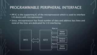
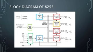
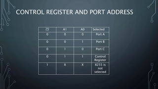
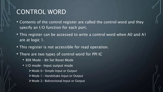
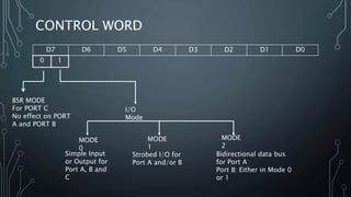
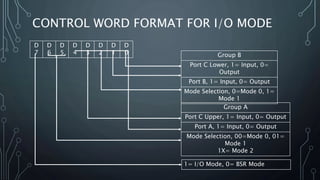
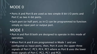
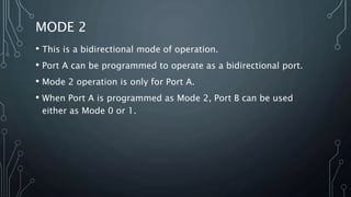
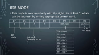
MICROPROCESSOR 8085
LECTURE 27
8255 PROGRAMMABLE PERIPHERAL INTERFACE
PROF. SANDIP DAS
PROGRAMMABLE PERIPHERAL INTERFACE
• PPI IC is the supporting IC of the microprocessor which is used to interface
I/O device with microprocessor.
• Since, microprocessor has fixed number of data and address bus lines and
none of the lines are dedicated for I/O interfacing.
8055 8255
Input
device
Output
device
Input
device
Port A
Port B
Port C
IC 8255
BLOCK DIAGRAM OF 8255
CONTROL REGISTER AND PORT ADDRESS
𝐶𝑆 A1 A0 Selected
0 0 0 Port A
0 0 1 Port B
0 1 0 Port C
0 1 1 Control
Register
1 X X 8255 is
not
selected
CONTROL WORD
• Contents of the control register are called the control word and they
specify an I/O function for each port.
• This register can be accessed to write a control word when A0 and A1
are at logic 1.
• This register is not accessible for read operation.
• There are two types of control word for PPI IC
• BSR Mode – Bit Set Reset Mode
• I/O mode- Input output mode
Mode 0- Simple Input or Output
Mode 1- Handshake Input or Output
Mode 2- Bidirectional Input or Output
CONTROL WORD
D7 D6 D5 D4 D3 D2 D1 D0
0 1
BSR MODE
For PORT C
No effect on PORT
A and PORT B
I/O
Mode
MODE
0
MODE
1
MODE
2
Simple Input
or Output for
Port A, B and
C
Strobed I/O for
Port A and/or B
Bidirectional data bus
for Port A
Port B: Either in Mode 0
or 1
CONTROL WORD FORMAT FOR I/O MODE
D
7
D
6
D
5
D
4
D
3
D
2
D
1
D
0 Group B
Port C Lower, 1= Input, 0=
Output
Port B, 1= Input, 0= Output
Mode Selection, 0=Mode 0, 1=
Mode 1
Group A
Port C Upper, 1= Input, 0= Output
Port A, 1= Input, 0= Output
Mode Selection, 00=Mode 0, 01=
Mode 1
1X= Mode 2
1= I/O Mode, 0= BSR Mode
MODE 0
• Ports A and Port B are used as two simple 8 bit I/O ports and
Port C as two 4-bit ports.
• Each port (or half port, as in C) can be programmed to function
simply as input port or output port.
MODE 1
• Port A and Port B both are designed to operate in this mode of
operation.
• When Port A and B are programmed in Mode 1 and are
configured as input ports, then, Port A uses the upper three
signals of Port C: PC3, PC4, PC5 where as Port B uses the lower
three signals of Port C: PC2, PC1 and PC0.
MODE 2
• This is a bidirectional mode of operation.
• Port A can be programmed to operate as a bidirectional port.
• Mode 2 operation is only for Port A.
• When Port A is programmed as Mode 2, Port B can be used
either as Mode 0 or 1.
BSR MODE
• This mode is concerned only with the eight bits of Port C, which
can be set/reset by writing appropriate control word.
D7 D6 D5 D4 D3 D2 D1 D0
0 X X X Bit Select Set/Rese
t
BSR
mode Not used,
Generally set to
0
000= Bit 0
001= Bit 1
010= Bit 2
011= Bit 3
100= Bit 4
101= Bit 5
110= Bit 6
111= Bit 7
1= Set
0= Reset

25. 8255 programmable peripheral interface

  • 1.
    MICROPROCESSOR 8085 LECTURE 27 8255PROGRAMMABLE PERIPHERAL INTERFACE PROF. SANDIP DAS
  • 2.
    PROGRAMMABLE PERIPHERAL INTERFACE •PPI IC is the supporting IC of the microprocessor which is used to interface I/O device with microprocessor. • Since, microprocessor has fixed number of data and address bus lines and none of the lines are dedicated for I/O interfacing. 8055 8255 Input device Output device Input device Port A Port B Port C
  • 3.
  • 4.
  • 5.
    CONTROL REGISTER ANDPORT ADDRESS 𝐶𝑆 A1 A0 Selected 0 0 0 Port A 0 0 1 Port B 0 1 0 Port C 0 1 1 Control Register 1 X X 8255 is not selected
  • 6.
    CONTROL WORD • Contentsof the control register are called the control word and they specify an I/O function for each port. • This register can be accessed to write a control word when A0 and A1 are at logic 1. • This register is not accessible for read operation. • There are two types of control word for PPI IC • BSR Mode – Bit Set Reset Mode • I/O mode- Input output mode Mode 0- Simple Input or Output Mode 1- Handshake Input or Output Mode 2- Bidirectional Input or Output
  • 7.
    CONTROL WORD D7 D6D5 D4 D3 D2 D1 D0 0 1 BSR MODE For PORT C No effect on PORT A and PORT B I/O Mode MODE 0 MODE 1 MODE 2 Simple Input or Output for Port A, B and C Strobed I/O for Port A and/or B Bidirectional data bus for Port A Port B: Either in Mode 0 or 1
  • 8.
    CONTROL WORD FORMATFOR I/O MODE D 7 D 6 D 5 D 4 D 3 D 2 D 1 D 0 Group B Port C Lower, 1= Input, 0= Output Port B, 1= Input, 0= Output Mode Selection, 0=Mode 0, 1= Mode 1 Group A Port C Upper, 1= Input, 0= Output Port A, 1= Input, 0= Output Mode Selection, 00=Mode 0, 01= Mode 1 1X= Mode 2 1= I/O Mode, 0= BSR Mode
  • 9.
    MODE 0 • PortsA and Port B are used as two simple 8 bit I/O ports and Port C as two 4-bit ports. • Each port (or half port, as in C) can be programmed to function simply as input port or output port. MODE 1 • Port A and Port B both are designed to operate in this mode of operation. • When Port A and B are programmed in Mode 1 and are configured as input ports, then, Port A uses the upper three signals of Port C: PC3, PC4, PC5 where as Port B uses the lower three signals of Port C: PC2, PC1 and PC0.
  • 10.
    MODE 2 • Thisis a bidirectional mode of operation. • Port A can be programmed to operate as a bidirectional port. • Mode 2 operation is only for Port A. • When Port A is programmed as Mode 2, Port B can be used either as Mode 0 or 1.
  • 11.
    BSR MODE • Thismode is concerned only with the eight bits of Port C, which can be set/reset by writing appropriate control word. D7 D6 D5 D4 D3 D2 D1 D0 0 X X X Bit Select Set/Rese t BSR mode Not used, Generally set to 0 000= Bit 0 001= Bit 1 010= Bit 2 011= Bit 3 100= Bit 4 101= Bit 5 110= Bit 6 111= Bit 7 1= Set 0= Reset