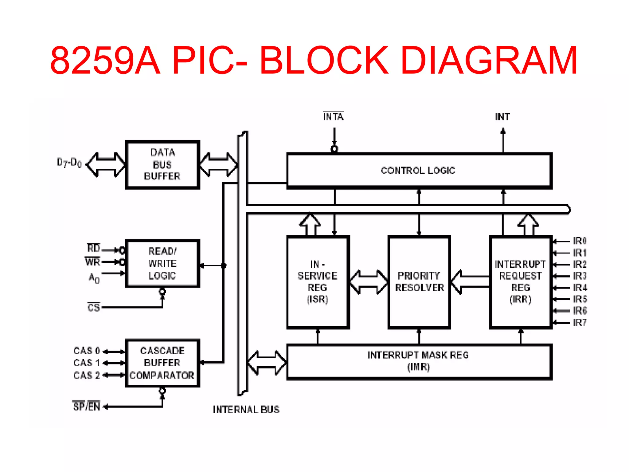
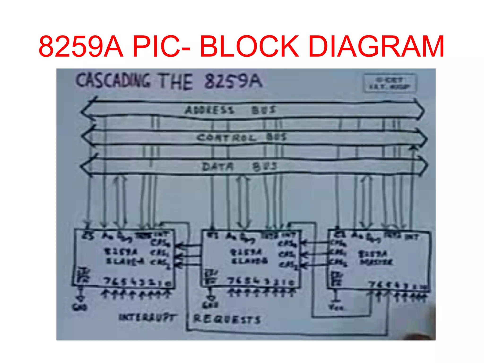
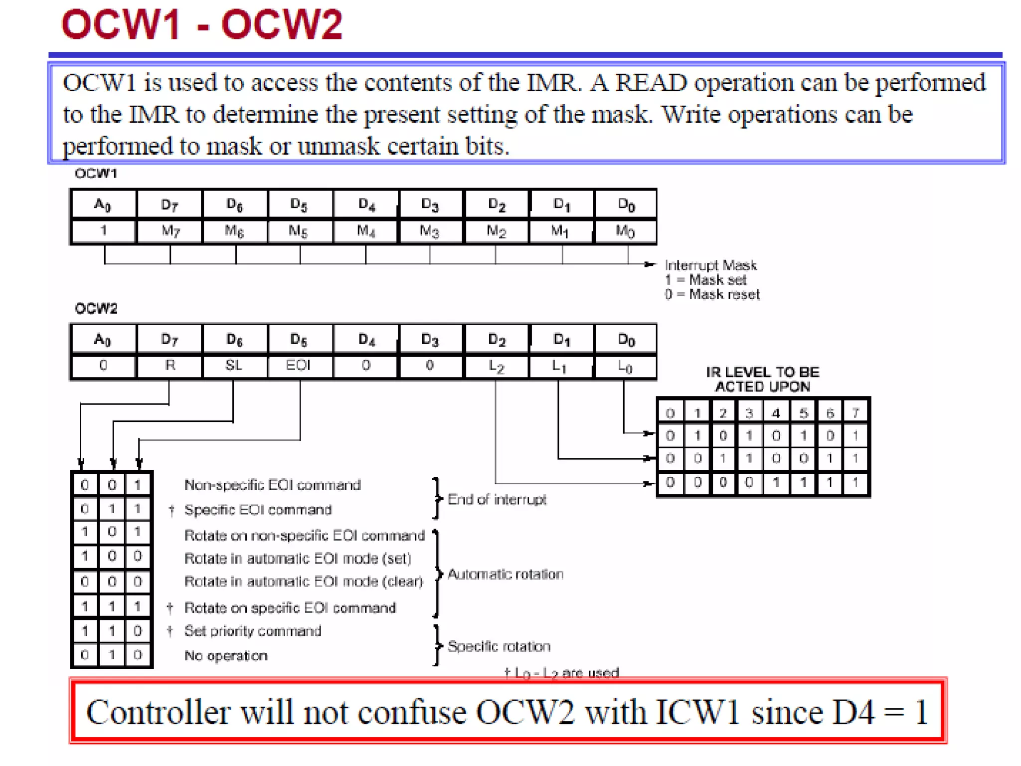
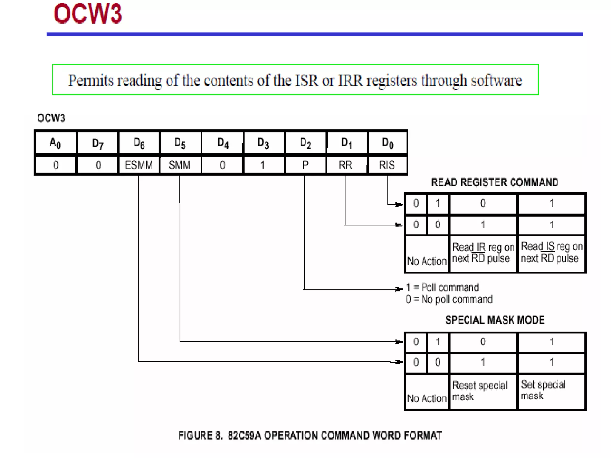
8259A PROGRAMMABLE 
INTERRUPT CONTROLLER
Interrupt handling by 
CPU vs. 8259
Why 8259A ?? 
• 8085 Processor has only 5 hardware interrupts to handle 
a maximum of 5 I/O devices. 
(RST 7.5, RST6.5, RST 5.5, INTR, TRAP) 
• If the I/O devices are more than 5, more number of 
interrupt pins are required. 
• In such case of multiple interrupt systems 8259 – PIC is 
designed to care of the interrupts. 
• Every 8259 IC can handle a maximum of 8 interrupts 
along with priorities.
• When an interrupts occurs ,it Vectors an interrupt request to the 
vector table. 
• However all the 8 interrupts are spaced at an interval of four to 
eight locations. 
• Resolve 8 levels of interrupt priorities in variety of modes & 
Mask each interrupt request individually. 
• Read the status of pending interrupts, in-service interrupts and 
masked interrupts. 
• Accepts either the level triggered or edge triggered interrupt 
request. 
• Expandable to 64 priority levels by cascading additional 8259As & 
compatible with 8-bit as well as 16-bit processors.
8259A PIC- BLOCK DIAGRAM 
It includes 8 blocks. 
• Control logic 
• Read/Write logic 
• Data bus buffer 
• Three registers (IRR,ISR and IMR) 
• Priority resolver 
• Cascade Buffer
8259A PIC- PIN DIGRAM
8259A PIC- BLOCK DIAGRAM
8259A PIC- INTERRUPTS AND CONTROL 
LOGIC SECTION 
This section consists of 
• IRR (Interrupt Request 
Register) 
• ISR (In-Service Register) 
• Priority Resolver 
• IMR (Interrupt Mask 
Register) 
• Control logic block 
IRR 
• 8 interrupt inputs set 
corresponding bits of IRR 
• Used to store the 
information about the 
interrupt inputs 
requesting service.
8259A PIC- INTERRUPTS AND CONTROL 
LOGIC SECTION 
ISR 
• Used to store information 
about the interrupts 
currently being serviced. 
PRIORITY RESOLVER 
• Examines three registers and 
determines whether INT 
should be sent to MPU. 
• Determines the priorities of the 
bits set in IRR as dictated by 
priority mode set by OCWs. 
• The bit corresponding to 
highest priority input is set in 
ISR during input.
8259A PIC- INTERRUPTS AND CONTROL 
LOGIC SECTION 
IMR 
• This register can be programmed by an OCW to store 
the bits which mask specific interrupts. 
• An interrupt which is masked by software (By 
programming the IMR) will not be recognized and 
serviced even if it sets corresponding bits in the IRR.
8259A PIC- INTERRUPTS AND CONTROL 
LOGIC SECTION 
CONTROL LOGIC 
• Has two pins: 
INT (Interrupt) Output 
( Interrupt Acknowledge) Input 
• INT Connected to Interrupt pin of MPU. 
 When interrupt occurs this pin goes high.
8259A PIC- BLOCK DIAGRAM 
DATA BUS BUFFER 
• 8 bit 
• Bidirectional 
• Tri-state Buffer used to Interface the 8259 to the 
system data bus. 
• Control words, Status words and vectoring data 
are all passed through the data bus buffer.
8259A PIC- READ/WRITE CONTROL LOGIC 
SECTION 
• Contains ICW and OCW registers programmed by the 
CPU to set up the 8259 to operate in various modes. 
• Also accepts read command from CPU to permit the 
CPU to read status words. 
•  Chip Select  Active Low input 
 Used to select the Device. 
•  Read  Active Low input 
 Used by CPU to read the status of 
ISR,IRR,IMR or the Interrupt level. 
•  Write  Active Low input 
 Used to write OCW and ICW onto the 8259. 
*ICW Initialization Control Word 
OCW Operation Control Word
8259A PIC- CASCADE BUFFER/ 
COMPARATOR 
• Generates control signals for cascade operation. 
• 8259 cascaded with other 8259s 
 Interrupt handling capacity to 64 levels 
 Former is called master and latter is slave. 
• 8259 can be set up as master or slave by
8259A PIC- CASCADE BUFFER/ 
COMPARATOR 
CAS 0-2 
• For master 8259 these pins are outputs and for slaves these are 
inputs. 
• When 8259 is a master the CALL op-code is generated by master in 
response to the first Interrupt acknowledge. 
• The vectoring address must be released by slave 8259. 
• The master puts out the identification code to select one of the slave 
from 8 slaves through these pins. 
• The slave thus selected puts out the address of ISR during second 
and third interrupt acknowledge pulses from the CPU.
Interrupt Sequence 
Following events occur: 
1) One or more interrupt request lines(IR0-IR7) are raised high. 
2) Priority resolver checks for the 3 register and sets INT high. 
3) In response to INTR signal 8085 mp sends an INTA pulse. 
4) Upon receiving INTA from 8085, corresponding IRR 
line(IR0-IR7) is reset. 
4) 8259 places the opcode for call instruction. 
5) Call instruction initiates two more interrupt acknowledge 
cycles. 
6) During the two interrupt acknowledge cycles, 8259 places 
the lower byte of ISR and higher byte of ISR address. 
7) When interrupt cycle is completed an EOI command is 
issued by the microprocessor.
8259A- OPERATING MODES 
FULLY NESTED MODE: 
• General purpose mode / default mode. 
• IR0 to IR7 are arranged from highest to lowest. 
• IR0 Highest IR7Lowest 
AUTOMATIC ROTATION MODE: 
• In this mode, a device after being serviced, receives the 
lowest priority. 
SPECIFIC ROTATION MODE: 
• Similar to automatic rotation mode, except that the user 
can select any IR for the lowest priority, thus fixing all 
other priorities.
8259-INTERRUPT PROCESS IN FULLY NESTED MODE
8259A- OPERATING MODES 
END OF INTERRUPT (EOI): 
• After the completion of an interrupt service, the 
corresponding ISR bits needs to be reset to update the 
information in the ISR. This is called EOI command. 
It can be issued in three formats: 
NON SPECIFIC EOI COMMAND:(manually) 
• When this command is sent to 8259A, it resets the 
highest priority ISR bit. 
SPECIFIC EOI COMMAND:(manually) 
• This command specifies which ISR bit is to reset.
8259A- OPERATING MODES 
AUTOMATIC EOI: 
• In this mode, no command is necessary. 
• During the end of interrupt acknowledge cycle, the ISR 
bit is reset. 
• Used for master only
Command words (ICW & OCW) 
The command words of 8259A are classified in two groups, 
1) Initialization command words (ICWs) 
(Total of 4 –ICWs) 
2) Operation command words (OCWs) 
(Total of 3 - OCWs) 
8259 must be initialized by writing two to four command 
words into their respective command word registers. 
If A0=0,D4=1: The control word is ICW1 
If A0=1: The control word is ICW2
ICW1 and ICW2 are compulsory 
command words for initialization sequence 
of 8259A while ICW3 and ICW4 are 
optional.
ADI=1 for 8086 based system 
For 8086 Don’t Care
For 8085 system they are filled by A15-A11 of the interrupt vector address and 
Least significant 3 bits are same as the respective bits of the vector address. 
For 8086 system they are filled by most significant 5 bits of interrupt type and 
the least significant 3 bits are 0, pointing to IR0.
8259 updated
8259 updated

8259 updated

  • 1.
  • 2.
    Interrupt handling by CPU vs. 8259
  • 3.
    Why 8259A ?? • 8085 Processor has only 5 hardware interrupts to handle a maximum of 5 I/O devices. (RST 7.5, RST6.5, RST 5.5, INTR, TRAP) • If the I/O devices are more than 5, more number of interrupt pins are required. • In such case of multiple interrupt systems 8259 – PIC is designed to care of the interrupts. • Every 8259 IC can handle a maximum of 8 interrupts along with priorities.
  • 4.
    • When aninterrupts occurs ,it Vectors an interrupt request to the vector table. • However all the 8 interrupts are spaced at an interval of four to eight locations. • Resolve 8 levels of interrupt priorities in variety of modes & Mask each interrupt request individually. • Read the status of pending interrupts, in-service interrupts and masked interrupts. • Accepts either the level triggered or edge triggered interrupt request. • Expandable to 64 priority levels by cascading additional 8259As & compatible with 8-bit as well as 16-bit processors.
  • 5.
    8259A PIC- BLOCKDIAGRAM It includes 8 blocks. • Control logic • Read/Write logic • Data bus buffer • Three registers (IRR,ISR and IMR) • Priority resolver • Cascade Buffer
  • 6.
  • 7.
  • 8.
  • 9.
    8259A PIC- INTERRUPTSAND CONTROL LOGIC SECTION This section consists of • IRR (Interrupt Request Register) • ISR (In-Service Register) • Priority Resolver • IMR (Interrupt Mask Register) • Control logic block IRR • 8 interrupt inputs set corresponding bits of IRR • Used to store the information about the interrupt inputs requesting service.
  • 10.
    8259A PIC- INTERRUPTSAND CONTROL LOGIC SECTION ISR • Used to store information about the interrupts currently being serviced. PRIORITY RESOLVER • Examines three registers and determines whether INT should be sent to MPU. • Determines the priorities of the bits set in IRR as dictated by priority mode set by OCWs. • The bit corresponding to highest priority input is set in ISR during input.
  • 11.
    8259A PIC- INTERRUPTSAND CONTROL LOGIC SECTION IMR • This register can be programmed by an OCW to store the bits which mask specific interrupts. • An interrupt which is masked by software (By programming the IMR) will not be recognized and serviced even if it sets corresponding bits in the IRR.
  • 12.
    8259A PIC- INTERRUPTSAND CONTROL LOGIC SECTION CONTROL LOGIC • Has two pins: INT (Interrupt) Output ( Interrupt Acknowledge) Input • INT Connected to Interrupt pin of MPU.  When interrupt occurs this pin goes high.
  • 13.
    8259A PIC- BLOCKDIAGRAM DATA BUS BUFFER • 8 bit • Bidirectional • Tri-state Buffer used to Interface the 8259 to the system data bus. • Control words, Status words and vectoring data are all passed through the data bus buffer.
  • 14.
    8259A PIC- READ/WRITECONTROL LOGIC SECTION • Contains ICW and OCW registers programmed by the CPU to set up the 8259 to operate in various modes. • Also accepts read command from CPU to permit the CPU to read status words. •  Chip Select  Active Low input  Used to select the Device. •  Read  Active Low input  Used by CPU to read the status of ISR,IRR,IMR or the Interrupt level. •  Write  Active Low input  Used to write OCW and ICW onto the 8259. *ICW Initialization Control Word OCW Operation Control Word
  • 15.
    8259A PIC- CASCADEBUFFER/ COMPARATOR • Generates control signals for cascade operation. • 8259 cascaded with other 8259s  Interrupt handling capacity to 64 levels  Former is called master and latter is slave. • 8259 can be set up as master or slave by
  • 16.
    8259A PIC- CASCADEBUFFER/ COMPARATOR CAS 0-2 • For master 8259 these pins are outputs and for slaves these are inputs. • When 8259 is a master the CALL op-code is generated by master in response to the first Interrupt acknowledge. • The vectoring address must be released by slave 8259. • The master puts out the identification code to select one of the slave from 8 slaves through these pins. • The slave thus selected puts out the address of ISR during second and third interrupt acknowledge pulses from the CPU.
  • 17.
    Interrupt Sequence Followingevents occur: 1) One or more interrupt request lines(IR0-IR7) are raised high. 2) Priority resolver checks for the 3 register and sets INT high. 3) In response to INTR signal 8085 mp sends an INTA pulse. 4) Upon receiving INTA from 8085, corresponding IRR line(IR0-IR7) is reset. 4) 8259 places the opcode for call instruction. 5) Call instruction initiates two more interrupt acknowledge cycles. 6) During the two interrupt acknowledge cycles, 8259 places the lower byte of ISR and higher byte of ISR address. 7) When interrupt cycle is completed an EOI command is issued by the microprocessor.
  • 18.
    8259A- OPERATING MODES FULLY NESTED MODE: • General purpose mode / default mode. • IR0 to IR7 are arranged from highest to lowest. • IR0 Highest IR7Lowest AUTOMATIC ROTATION MODE: • In this mode, a device after being serviced, receives the lowest priority. SPECIFIC ROTATION MODE: • Similar to automatic rotation mode, except that the user can select any IR for the lowest priority, thus fixing all other priorities.
  • 19.
    8259-INTERRUPT PROCESS INFULLY NESTED MODE
  • 20.
    8259A- OPERATING MODES END OF INTERRUPT (EOI): • After the completion of an interrupt service, the corresponding ISR bits needs to be reset to update the information in the ISR. This is called EOI command. It can be issued in three formats: NON SPECIFIC EOI COMMAND:(manually) • When this command is sent to 8259A, it resets the highest priority ISR bit. SPECIFIC EOI COMMAND:(manually) • This command specifies which ISR bit is to reset.
  • 21.
    8259A- OPERATING MODES AUTOMATIC EOI: • In this mode, no command is necessary. • During the end of interrupt acknowledge cycle, the ISR bit is reset. • Used for master only
  • 22.
    Command words (ICW& OCW) The command words of 8259A are classified in two groups, 1) Initialization command words (ICWs) (Total of 4 –ICWs) 2) Operation command words (OCWs) (Total of 3 - OCWs) 8259 must be initialized by writing two to four command words into their respective command word registers. If A0=0,D4=1: The control word is ICW1 If A0=1: The control word is ICW2
  • 23.
    ICW1 and ICW2are compulsory command words for initialization sequence of 8259A while ICW3 and ICW4 are optional.
  • 25.
    ADI=1 for 8086based system For 8086 Don’t Care
  • 26.
    For 8085 systemthey are filled by A15-A11 of the interrupt vector address and Least significant 3 bits are same as the respective bits of the vector address. For 8086 system they are filled by most significant 5 bits of interrupt type and the least significant 3 bits are 0, pointing to IR0.