Downloaded 469 times
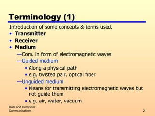
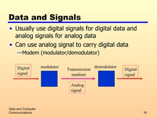
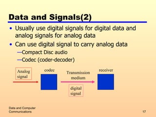
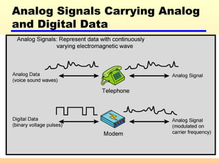
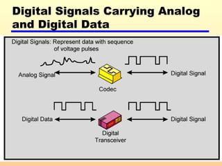
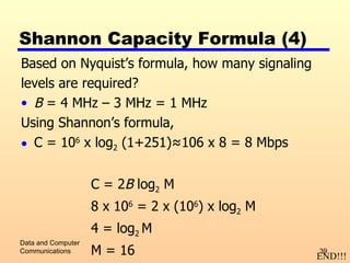

The document introduces some key concepts in data communication, including: 1) Different types of transmission media such as guided (e.g. fiber optic cable) and unguided (e.g. wireless). 2) Analog and digital signals and how analog data can be transmitted using either type of signal. 3) Factors that can impair transmission such as attenuation, delay distortion, and different types of noise. The Nyquist bandwidth and Shannon capacity formulas for calculating maximum data rates are also covered.