


![According to the Clos criterion: n = (N/2) 1/2 k > 2 n – 1 Crosspoints ≥ 4N [(2N) 1/2 – 1] Note](https://image.slidesharecdn.com/ch08-100307211935-phpapp02/85/Ch08-37-320.jpg)


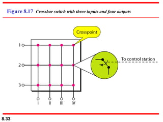
The document discusses different types of switched networks, including circuit-switched networks, datagram networks, and virtual-circuit networks. It provides examples of how each type can be used and their characteristics. The document also describes the structure of switches used in different network types, including crossbar switches, multistage switches, time-slot interchange switches, and banyan switches. Key aspects like resource reservation, routing, addressing, and delays are compared between the different network types.


![2[1].1 data transmission](https://cdn.slidesharecdn.com/ss_thumbnails/21-1-datatransmission-111203164944-phpapp01-thumbnail.jpg?width=640&height=640&fit=bounds)