This document provides a summary of key concepts in data communication and transmission including:
1) Communication models including simplex, half duplex, and full duplex transmission modes.
2) Analog and digital signals and their characteristics such as periodicity.
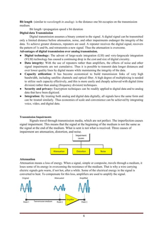
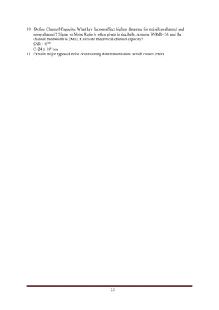
3) Concepts such as bandwidth, attenuation, noise, and Shannon's channel capacity formula that influence data transmission rates.


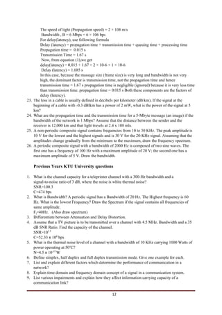
![Sine Wave
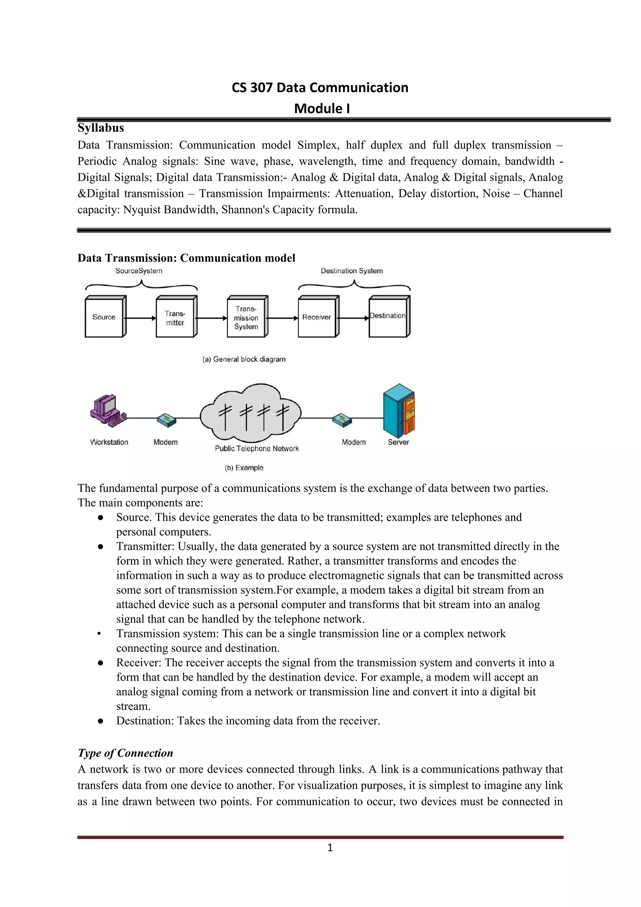
It is considered as a fundamental periodic signal. A general sine wave can be represented by three
parameters:
1.peak amplitude (A) - the maximum value or strength of the signal over time; typically measured in
volts.
2.frequency (f) - the rate [in cycles per second, or Hertz (Hz)] at which the signal repeats. An
equivalent parameter is the period (T) of a signal, so T = 1/f.
3.phase (φ) - measure of relative position in time within a single period of a signal.
Wavelength (λ)
Wavelength is the distance occupied by one cycle. It is also defined as distance between two points of
corresponding phase in two consecutive cycles.
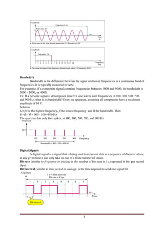
Time And Frequency Domain
The frequency domain refers to the analysis of mathematical functions or signals with
respect to frequency, rather than time. A time-domain graph shows how a signal changes over time,
whereas a frequency-domain graph shows how much of the signal lies within each given frequency
band over a range of frequencies. A frequency-domain representation can also include information on
the phase shift .
time domain concept :time v/s amplitude
frequency domain concept : frequency v/s amplitude
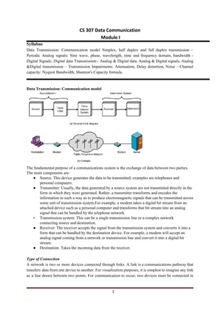
4](https://image.slidesharecdn.com/dc1-220411062712/85/dc1-pdf-4-320.jpg)