Downloaded 120 times
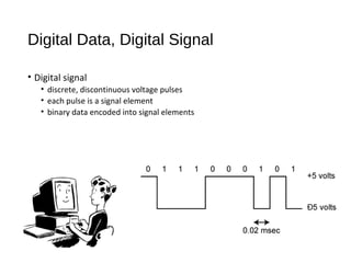
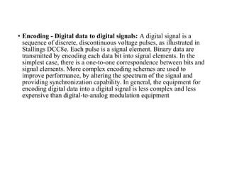
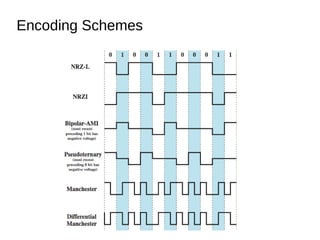
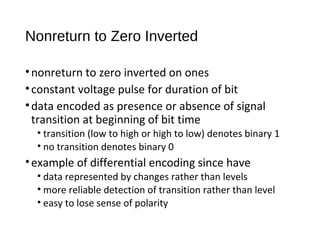
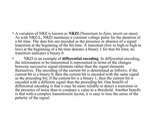
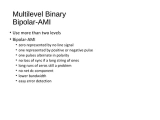
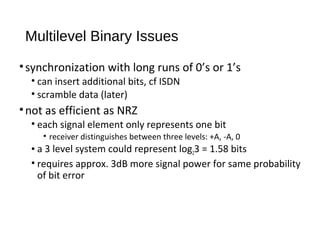
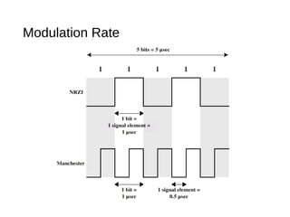
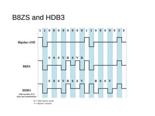


Digital signals can be encoded in various ways: 1) NRZ-L uses two voltage levels to represent 0s and 1s, maintaining a constant level during each bit. 2) NRZI represents 1s as transitions and 0s as no transitions at the start of each bit. 3) Bipolar-AMI represents 0s as no signal and alternating positive and negative pulses for 1s, eliminating long runs of the same signal.


![2[1].1 data transmission](https://cdn.slidesharecdn.com/ss_thumbnails/21-1-datatransmission-111203164944-phpapp01-thumbnail.jpg?width=640&height=640&fit=bounds)


![[Deck] What's New in Spark-Iceberg Integration via DSV2.pptx](https://cdn.slidesharecdn.com/ss_thumbnails/deckwhatsnewinspark-icebergintegrationviadsv2-260210005337-25955b12-thumbnail.jpg?width=640&height=640&fit=bounds)


