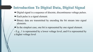
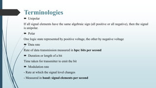
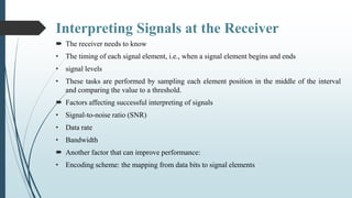
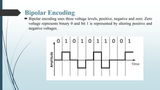
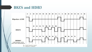
SlideShare a Scribd company logo
Prepared By:
BIPLAP BHATTARAI
Introduction To Digital Data, Digital Signal
Digital signal is a sequence of discrete, discontinuous voltage pulses.
Each pulse is a signal element.
Binary data are transmitted by encoding the bit stream into signal
elements.
In the simplest case, one bit is represented by one signal element.
- E.g., 1 is represented by a lower voltage level, and 0 is represented by
a higher voltage level
Terminologies
 Unipolar
If all signal elements have the same algebraic sign (all positive or all negative), then the signal
is unipolar.
 Polar
One logic state represented by positive voltage, the other by negative voltage
 Data rate
Rate of data transmission measured in bps: bits per second
 Duration or length of a bit
Time taken for transmitter to emit the bit
 Modulation rate
- Rate at which the signal level changes
- Measured in baud: signal elements per second
Interpreting Signals at the Receiver
 The receiver needs to know
• The timing of each signal element, i.e., when a signal element begins and ends
• signal levels
• These tasks are performed by sampling each element position in the middle of the interval
and comparing the value to a threshold.
 Factors affecting successful interpreting of signals
• Signal-to-noise ratio (SNR)
• Data rate
• Bandwidth
 Another factor that can improve performance:
• Encoding scheme: the mapping from data bits to signal elements
Line Coding
 The process for converting digital data into digital signal is said to be Line
Coding.
 Line Coding Helps Error detection - errors occur during transmission due to
line impairments. Some codes are constructed such that when an error
occurs it can be detected.
 Noise and interference - there are line encoding techniques that make the
transmitted signal “immune” to noise and interference. This means that the
signal cannot be corrupted, it is stronger than error detection.
 Complexity - the more robust and resilient the code, the more complex it is
to implement and the price is often paid in baud rate or required bandwidth.
Uni-polar Encoding
 Unipolar encoding schemes use single voltage level to represent data. In this case, to
represent binary 1, high voltage is transmitted and to represent 0, no voltage is transmitted.
 It is also called Unipolar-Non-return-to-zero, because there is no rest condition i.e. it either
represents 1 or 0.
Polar Encoding
 Polar encoding scheme uses multiple voltage levels to represent binary values. Polar
encodings is available in four types:
 Polar Non-Return to Zero (Polar NRZ)
• It uses two different voltage levels to represent binary values. Generally, positive voltage
represents 1 and negative value represents 0. It is also NRZ because there is no rest
condition.
• NRZ scheme has two variants: NRZ-L and NRZ-I.
 NRZ-L changes voltage level at when a different
bit is encountered whereas NRZ-I changes voltage
when a 1 is encountered.
Polar Encoding
 PolarReturn to Zero (RZ)
• Problem with NRZ is that the receiver cannot conclude when a bit ended and when the next
bit is started, in case when sender and receiver’s clock are not synchronized.
• RZ uses three voltage levels, positive voltage to represent 1, negative voltage to represent 0
and zero voltage for none. Signals change during bits not between bits.
 Manchester
• This encoding scheme is a combination of RZ and NRZ-L. Bit time is divided into two
halves. It transits in the middle of the bit and changes phase when a different bit is
encountered.
 Differential Manchester
• This encoding scheme is a combination of RZ and NRZ-I. It also transit at the middle of the
bit but changes phase only when 1 is encountered.
Bipolar Encoding
 Bipolar encoding uses three voltage levels, positive, negative and zero. Zero
voltage represents binary 0 and bit 1 is represented by altering positive and
negative voltages.
Problems on Uni- Polar Encoding
If you encode a long series of ones using unipolar/on-off signaling,
then the DC component could fully charge a capacitor, resulting in
errors as the signal is brought to zero.
With bi-polar signaling, long series of ones are encoded as
alternating negative and positive voltages, so the average voltage is
zero, which eliminates the DC component issue.
The constant transitions on ones with bipolar signaling also allows
the circuit to be self clocking, which eliminates the need for a separate
clock source.
So Why Not Bi- Polar Encoding ?
Although, the constant transitions on ones with bipolar signaling
also allows the circuit to be self clocking, which eliminates the need
for a separate clock source.
But then you still have issues with runs of zeroes causing a lack of
transitions to clock on. This issue has been dealt with using several
methods.
 And that is Dealt with Scrambling Technique.
Scrambling
Scrambling is a technique used to create a sequence of bits that has the
required self clocking, no low frequencies, no wide bandwidth.
It is implemented at the same time as encoding, the bit stream is created on
the fly.
The best code is one that does not increase the bandwidth for
synchronization and has no DC components.
It replaces ‘unfriendly’ runs of bits with a violation code that is easy to
recognize.
Scrambling Cont..
Use scrambling to replace sequences that would produce constant voltage
these filling sequences must:
• Sequences that would result in a constant voltage are replaced by filling sequences that
will provide sufficient transitions for the receiver’s clock to maintain synchronization.
• Filling sequences must be recognized by receiver and replaced with original data
sequence.
• Filling sequence is the same length as original sequence.
Design goals
• have no dc component
• have no long sequences of zero level line signal
• have no reduction in data rate
• give error detection capability
Alternate Mark Inversion (AMI) used with
scrambling
Scrambling Techniques
 Bipolar With 8-Zeros Substitution
 Based on bipolar-AMI, whose drawback is a long string of zeros may
result in loss of synchronization.
 If octet of all zeros occurs and the last voltage pulse preceding this
octet was positive, encode as 000+-0-+ or 000VB0VB.
 If octet of all zeros occurs and the last voltage pulse preceding this
octet was negative, encode as 000-+0+-
 Causes two violations of AMI code:
• Unlikely to occur as a result of noise
• Receiver recognizes the pattern and interprets the octet as consisting
of all zeros.
A. B8ZS
Two cases of B8ZS scrambling technique
 The main formula for B8ZS is 000VB0VB
Where V
 stands for “violation bit”
 Follows the polarity of previous non-zero bit
B
 stands for “bipolar bit” or “balance bit”
 Inverses the polarity of previous non-zero bit
 High-Density Bipolar-3 Zeros
 Based on bipolar-AMI
 String of four zeros is replaced with sequences containing one or two
pulses.
B. HDB3
Number of Bipolar Pulses since last
substitution
Polarity of
Preceding Pulse
Odd Even
- 000- +00+
+ 000+ -00-
 HDB3 substitutes four consecutive zeros with 000V or B00V
depending on the number of nonzero pulses after the last
substitution.
 If no of non zero pulses is even the substitution is B00V to make total
non zero pulse even.
 If no of non zero pulses is odd the substitution is 000V to make total
non zero pulses even.
 Example 1 of HDB3 encoding
The pattern of bits " 1 0 0 0 0 1 1 0 “
encoded in HDB3 is " + 0 0 0 V - + 0 "
(the corresponding encoding using AMI is " + 0 0 0 0 - + ").
Different situations in HDB3 scrambling technique
Example 2 of HDB3 encoding
The pattern of bits " 1 0 1 0 0 0 0 0 1 1 0 0 0 0 1 1 0 0 0 0 0 0 "
encoded in HDB3 is " + 0 - 0 0 0 V 0 + - B 0 0 V - + B 0 0 V 0 0 "
which is: " + 0 - 0 0 0 - 0 + - + 0 0 + - + - 0 0 - 0 0 "
B8ZS and HDB3
Special Thanks
Mr. Shree Krishna Khadka
KIST College Of Science And Technology
Digital Data, Digital Signal | Scrambling Techniques

More Related Content

What's hot

Data Encoding
Data EncodingData Encoding
Data Encoding
Luka M G
 

What's hot (20)

Digital Data to Digital Signal Conversion
Digital Data to Digital Signal ConversionDigital Data to Digital Signal Conversion
Digital Data to Digital Signal Conversion
 
Delta Modulation
Delta ModulationDelta Modulation
Delta Modulation
 
Dc unit iii final ppt
Dc unit iii final pptDc unit iii final ppt
Dc unit iii final ppt
 
Base band transmission
Base band transmissionBase band transmission
Base band transmission
 
Arm instruction set
Arm instruction setArm instruction set
Arm instruction set
 
Data Communication & Computer Networks : Unipolar & Polar coding
Data Communication & Computer Networks : Unipolar & Polar codingData Communication & Computer Networks : Unipolar & Polar coding
Data Communication & Computer Networks : Unipolar & Polar coding
 
Lecture 17
Lecture 17Lecture 17
Lecture 17
 
Multiple access techniques for wireless communications
Multiple access techniques for wireless communicationsMultiple access techniques for wireless communications
Multiple access techniques for wireless communications
 
EEP306: Line coding
EEP306: Line codingEEP306: Line coding
EEP306: Line coding
 
Equalization
EqualizationEqualization
Equalization
 
TWO STAGE NETWORKS
TWO STAGE NETWORKSTWO STAGE NETWORKS
TWO STAGE NETWORKS
 
Matched filter
Matched filterMatched filter
Matched filter
 
Encoding Techniques
Encoding TechniquesEncoding Techniques
Encoding Techniques
 
Convolution Codes
Convolution CodesConvolution Codes
Convolution Codes
 
Hamming codes
Hamming codesHamming codes
Hamming codes
 
BIT Error Rate
BIT Error RateBIT Error Rate
BIT Error Rate
 
FHSS- Frequency Hop Spread Spectrum
FHSS- Frequency Hop Spread SpectrumFHSS- Frequency Hop Spread Spectrum
FHSS- Frequency Hop Spread Spectrum
 
Time Division Multiplexing
Time Division MultiplexingTime Division Multiplexing
Time Division Multiplexing
 
Error Detection And Correction
Error Detection And CorrectionError Detection And Correction
Error Detection And Correction
 
Data Encoding
Data EncodingData Encoding
Data Encoding
 

Similar to Digital Data, Digital Signal | Scrambling Techniques

digital-analog_22222222222222222222222.pdf
digital-analog_22222222222222222222222.pdfdigital-analog_22222222222222222222222.pdf
digital-analog_22222222222222222222222.pdf
KiranG731731
 
Binary to digital encoding tbs 301
Binary to digital encoding tbs 301Binary to digital encoding tbs 301
Binary to digital encoding tbs 301
Bhupesh Rawat
 
base-band_digital_data_transmission-Line coding - Copy.ppt
base-band_digital_data_transmission-Line coding - Copy.pptbase-band_digital_data_transmission-Line coding - Copy.ppt
base-band_digital_data_transmission-Line coding - Copy.ppt
AbyThomas54
 
Line coding Tec hniques.pptx
Line coding Tec                 hniques.pptxLine coding Tec                 hniques.pptx
Line coding Tec hniques.pptx
naveen088888
 
Lec_CodingSchemes.pptx
Lec_CodingSchemes.pptxLec_CodingSchemes.pptx
Lec_CodingSchemes.pptx
slayHoaqin
 
Digital data transmission,line coding and pulse shaping
Digital data transmission,line coding and pulse shapingDigital data transmission,line coding and pulse shaping
Digital data transmission,line coding and pulse shaping
Aayush Kumar
 
Chap4 d t-d conversion
Chap4 d t-d conversionChap4 d t-d conversion
Chap4 d t-d conversion
arslan_akbar90
 

Similar to Digital Data, Digital Signal | Scrambling Techniques (20)

digital-analog_22222222222222222222222.pdf
digital-analog_22222222222222222222222.pdfdigital-analog_22222222222222222222222.pdf
digital-analog_22222222222222222222222.pdf
 
Lecture 08
Lecture 08Lecture 08
Lecture 08
 
Binary to digital encoding tbs 301
Binary to digital encoding tbs 301Binary to digital encoding tbs 301
Binary to digital encoding tbs 301
 
Unit 4
Unit 4Unit 4
Unit 4
 
base-band_digital_data_transmission-Line coding - Copy.ppt
base-band_digital_data_transmission-Line coding - Copy.pptbase-band_digital_data_transmission-Line coding - Copy.ppt
base-band_digital_data_transmission-Line coding - Copy.ppt
 
CCN
CCNCCN
CCN
 
Chapter2-PhysicalLayer.ppt
Chapter2-PhysicalLayer.pptChapter2-PhysicalLayer.ppt
Chapter2-PhysicalLayer.ppt
 
Data Encoding in Data Communication.pptx
Data Encoding in  Data Communication.pptxData Encoding in  Data Communication.pptx
Data Encoding in Data Communication.pptx
 
Lecture 08
Lecture 08Lecture 08
Lecture 08
 
Line coding Tec hniques.pptx
Line coding Tec                 hniques.pptxLine coding Tec                 hniques.pptx
Line coding Tec hniques.pptx
 
lec5_13.pptx
lec5_13.pptxlec5_13.pptx
lec5_13.pptx
 
Line coding
Line codingLine coding
Line coding
 
Lec_CodingSchemes.pptx
Lec_CodingSchemes.pptxLec_CodingSchemes.pptx
Lec_CodingSchemes.pptx
 
Dcn aasignment
Dcn aasignmentDcn aasignment
Dcn aasignment
 
Lecture 09
Lecture 09Lecture 09
Lecture 09
 
Digital data transmission,line coding and pulse shaping
Digital data transmission,line coding and pulse shapingDigital data transmission,line coding and pulse shaping
Digital data transmission,line coding and pulse shaping
 
Ch4 Data communication and networking by neha g. kurale
Ch4 Data communication and networking by neha g. kuraleCh4 Data communication and networking by neha g. kurale
Ch4 Data communication and networking by neha g. kurale
 
Ch05
Ch05Ch05
Ch05
 
line coding techniques, block coding and all type of coding
line coding techniques, block coding and all type of codingline coding techniques, block coding and all type of coding
line coding techniques, block coding and all type of coding
 
Chap4 d t-d conversion
Chap4 d t-d conversionChap4 d t-d conversion
Chap4 d t-d conversion
 

Recently uploaded

Online blood donation management system project.pdf
Online blood donation management system project.pdfOnline blood donation management system project.pdf
Online blood donation management system project.pdf
Kamal Acharya
 
Hall booking system project report .pdf
Hall booking system project report  .pdfHall booking system project report  .pdf
Hall booking system project report .pdf
Kamal Acharya
 
Fruit shop management system project report.pdf
Fruit shop management system project report.pdfFruit shop management system project report.pdf
Fruit shop management system project report.pdf
Kamal Acharya
 
RS Khurmi Machine Design Clutch and Brake Exercise Numerical Solutions
RS Khurmi Machine Design Clutch and Brake Exercise Numerical SolutionsRS Khurmi Machine Design Clutch and Brake Exercise Numerical Solutions
RS Khurmi Machine Design Clutch and Brake Exercise Numerical Solutions
Atif Razi
 

Recently uploaded (20)

Event Management System Vb Net Project Report.pdf
Event Management System Vb Net  Project Report.pdfEvent Management System Vb Net  Project Report.pdf
Event Management System Vb Net Project Report.pdf
 
Introduction to Casting Processes in Manufacturing
Introduction to Casting Processes in ManufacturingIntroduction to Casting Processes in Manufacturing
Introduction to Casting Processes in Manufacturing
 
Courier management system project report.pdf
Courier management system project report.pdfCourier management system project report.pdf
Courier management system project report.pdf
 
HYDROPOWER - Hydroelectric power generation
HYDROPOWER - Hydroelectric power generationHYDROPOWER - Hydroelectric power generation
HYDROPOWER - Hydroelectric power generation
 
2024 DevOps Pro Europe - Growing at the edge
2024 DevOps Pro Europe - Growing at the edge2024 DevOps Pro Europe - Growing at the edge
2024 DevOps Pro Europe - Growing at the edge
 
Online blood donation management system project.pdf
Online blood donation management system project.pdfOnline blood donation management system project.pdf
Online blood donation management system project.pdf
 
Cloud-Computing_CSE311_Computer-Networking CSE GUB BD - Shahidul.pptx
Cloud-Computing_CSE311_Computer-Networking CSE GUB BD - Shahidul.pptxCloud-Computing_CSE311_Computer-Networking CSE GUB BD - Shahidul.pptx
Cloud-Computing_CSE311_Computer-Networking CSE GUB BD - Shahidul.pptx
 
ONLINE CAR SERVICING SYSTEM PROJECT REPORT.pdf
ONLINE CAR SERVICING SYSTEM PROJECT REPORT.pdfONLINE CAR SERVICING SYSTEM PROJECT REPORT.pdf
ONLINE CAR SERVICING SYSTEM PROJECT REPORT.pdf
 
KIT-601 Lecture Notes-UNIT-3.pdf Mining Data Stream
KIT-601 Lecture Notes-UNIT-3.pdf Mining Data StreamKIT-601 Lecture Notes-UNIT-3.pdf Mining Data Stream
KIT-601 Lecture Notes-UNIT-3.pdf Mining Data Stream
 
NO1 Pandit Amil Baba In Bahawalpur, Sargodha, Sialkot, Sheikhupura, Rahim Yar...
NO1 Pandit Amil Baba In Bahawalpur, Sargodha, Sialkot, Sheikhupura, Rahim Yar...NO1 Pandit Amil Baba In Bahawalpur, Sargodha, Sialkot, Sheikhupura, Rahim Yar...
NO1 Pandit Amil Baba In Bahawalpur, Sargodha, Sialkot, Sheikhupura, Rahim Yar...
 
ENERGY STORAGE DEVICES INTRODUCTION UNIT-I
ENERGY STORAGE DEVICES  INTRODUCTION UNIT-IENERGY STORAGE DEVICES  INTRODUCTION UNIT-I
ENERGY STORAGE DEVICES INTRODUCTION UNIT-I
 
Hall booking system project report .pdf
Hall booking system project report  .pdfHall booking system project report  .pdf
Hall booking system project report .pdf
 
The Benefits and Techniques of Trenchless Pipe Repair.pdf
The Benefits and Techniques of Trenchless Pipe Repair.pdfThe Benefits and Techniques of Trenchless Pipe Repair.pdf
The Benefits and Techniques of Trenchless Pipe Repair.pdf
 
Scaling in conventional MOSFET for constant electric field and constant voltage
Scaling in conventional MOSFET for constant electric field and constant voltageScaling in conventional MOSFET for constant electric field and constant voltage
Scaling in conventional MOSFET for constant electric field and constant voltage
 
KIT-601 Lecture Notes-UNIT-4.pdf Frequent Itemsets and Clustering
KIT-601 Lecture Notes-UNIT-4.pdf Frequent Itemsets and ClusteringKIT-601 Lecture Notes-UNIT-4.pdf Frequent Itemsets and Clustering
KIT-601 Lecture Notes-UNIT-4.pdf Frequent Itemsets and Clustering
 
Fruit shop management system project report.pdf
Fruit shop management system project report.pdfFruit shop management system project report.pdf
Fruit shop management system project report.pdf
 
RS Khurmi Machine Design Clutch and Brake Exercise Numerical Solutions
RS Khurmi Machine Design Clutch and Brake Exercise Numerical SolutionsRS Khurmi Machine Design Clutch and Brake Exercise Numerical Solutions
RS Khurmi Machine Design Clutch and Brake Exercise Numerical Solutions
 
BRAKING SYSTEM IN INDIAN RAILWAY AutoCAD DRAWING
BRAKING SYSTEM IN INDIAN RAILWAY AutoCAD DRAWINGBRAKING SYSTEM IN INDIAN RAILWAY AutoCAD DRAWING
BRAKING SYSTEM IN INDIAN RAILWAY AutoCAD DRAWING
 
Arduino based vehicle speed tracker project
Arduino based vehicle speed tracker projectArduino based vehicle speed tracker project
Arduino based vehicle speed tracker project
 
Introduction to Machine Learning Unit-4 Notes for II-II Mechanical Engineering
Introduction to Machine Learning Unit-4 Notes for II-II Mechanical EngineeringIntroduction to Machine Learning Unit-4 Notes for II-II Mechanical Engineering
Introduction to Machine Learning Unit-4 Notes for II-II Mechanical Engineering
 

Digital Data, Digital Signal | Scrambling Techniques

  • 2. Introduction To Digital Data, Digital Signal Digital signal is a sequence of discrete, discontinuous voltage pulses. Each pulse is a signal element. Binary data are transmitted by encoding the bit stream into signal elements. In the simplest case, one bit is represented by one signal element. - E.g., 1 is represented by a lower voltage level, and 0 is represented by a higher voltage level
  • 3. Terminologies  Unipolar If all signal elements have the same algebraic sign (all positive or all negative), then the signal is unipolar.  Polar One logic state represented by positive voltage, the other by negative voltage  Data rate Rate of data transmission measured in bps: bits per second  Duration or length of a bit Time taken for transmitter to emit the bit  Modulation rate - Rate at which the signal level changes - Measured in baud: signal elements per second
  • 4. Interpreting Signals at the Receiver  The receiver needs to know • The timing of each signal element, i.e., when a signal element begins and ends • signal levels • These tasks are performed by sampling each element position in the middle of the interval and comparing the value to a threshold.  Factors affecting successful interpreting of signals • Signal-to-noise ratio (SNR) • Data rate • Bandwidth  Another factor that can improve performance: • Encoding scheme: the mapping from data bits to signal elements
  • 5. Line Coding  The process for converting digital data into digital signal is said to be Line Coding.  Line Coding Helps Error detection - errors occur during transmission due to line impairments. Some codes are constructed such that when an error occurs it can be detected.  Noise and interference - there are line encoding techniques that make the transmitted signal “immune” to noise and interference. This means that the signal cannot be corrupted, it is stronger than error detection.  Complexity - the more robust and resilient the code, the more complex it is to implement and the price is often paid in baud rate or required bandwidth.
  • 6. Uni-polar Encoding  Unipolar encoding schemes use single voltage level to represent data. In this case, to represent binary 1, high voltage is transmitted and to represent 0, no voltage is transmitted.  It is also called Unipolar-Non-return-to-zero, because there is no rest condition i.e. it either represents 1 or 0.
  • 7. Polar Encoding  Polar encoding scheme uses multiple voltage levels to represent binary values. Polar encodings is available in four types:  Polar Non-Return to Zero (Polar NRZ) • It uses two different voltage levels to represent binary values. Generally, positive voltage represents 1 and negative value represents 0. It is also NRZ because there is no rest condition. • NRZ scheme has two variants: NRZ-L and NRZ-I.  NRZ-L changes voltage level at when a different bit is encountered whereas NRZ-I changes voltage when a 1 is encountered.
  • 8. Polar Encoding  PolarReturn to Zero (RZ) • Problem with NRZ is that the receiver cannot conclude when a bit ended and when the next bit is started, in case when sender and receiver’s clock are not synchronized. • RZ uses three voltage levels, positive voltage to represent 1, negative voltage to represent 0 and zero voltage for none. Signals change during bits not between bits.  Manchester • This encoding scheme is a combination of RZ and NRZ-L. Bit time is divided into two halves. It transits in the middle of the bit and changes phase when a different bit is encountered.  Differential Manchester • This encoding scheme is a combination of RZ and NRZ-I. It also transit at the middle of the bit but changes phase only when 1 is encountered.
  • 9. Bipolar Encoding  Bipolar encoding uses three voltage levels, positive, negative and zero. Zero voltage represents binary 0 and bit 1 is represented by altering positive and negative voltages.
  • 10. Problems on Uni- Polar Encoding If you encode a long series of ones using unipolar/on-off signaling, then the DC component could fully charge a capacitor, resulting in errors as the signal is brought to zero. With bi-polar signaling, long series of ones are encoded as alternating negative and positive voltages, so the average voltage is zero, which eliminates the DC component issue. The constant transitions on ones with bipolar signaling also allows the circuit to be self clocking, which eliminates the need for a separate clock source.
  • 11. So Why Not Bi- Polar Encoding ? Although, the constant transitions on ones with bipolar signaling also allows the circuit to be self clocking, which eliminates the need for a separate clock source. But then you still have issues with runs of zeroes causing a lack of transitions to clock on. This issue has been dealt with using several methods.  And that is Dealt with Scrambling Technique.
  • 12. Scrambling Scrambling is a technique used to create a sequence of bits that has the required self clocking, no low frequencies, no wide bandwidth. It is implemented at the same time as encoding, the bit stream is created on the fly. The best code is one that does not increase the bandwidth for synchronization and has no DC components. It replaces ‘unfriendly’ runs of bits with a violation code that is easy to recognize.
  • 13. Scrambling Cont.. Use scrambling to replace sequences that would produce constant voltage these filling sequences must: • Sequences that would result in a constant voltage are replaced by filling sequences that will provide sufficient transitions for the receiver’s clock to maintain synchronization. • Filling sequences must be recognized by receiver and replaced with original data sequence. • Filling sequence is the same length as original sequence. Design goals • have no dc component • have no long sequences of zero level line signal • have no reduction in data rate • give error detection capability
  • 14. Alternate Mark Inversion (AMI) used with scrambling
  • 15. Scrambling Techniques  Bipolar With 8-Zeros Substitution  Based on bipolar-AMI, whose drawback is a long string of zeros may result in loss of synchronization.  If octet of all zeros occurs and the last voltage pulse preceding this octet was positive, encode as 000+-0-+ or 000VB0VB.  If octet of all zeros occurs and the last voltage pulse preceding this octet was negative, encode as 000-+0+-  Causes two violations of AMI code: • Unlikely to occur as a result of noise • Receiver recognizes the pattern and interprets the octet as consisting of all zeros. A. B8ZS
  • 16. Two cases of B8ZS scrambling technique  The main formula for B8ZS is 000VB0VB Where V  stands for “violation bit”  Follows the polarity of previous non-zero bit B  stands for “bipolar bit” or “balance bit”  Inverses the polarity of previous non-zero bit
  • 17.  High-Density Bipolar-3 Zeros  Based on bipolar-AMI  String of four zeros is replaced with sequences containing one or two pulses. B. HDB3 Number of Bipolar Pulses since last substitution Polarity of Preceding Pulse Odd Even - 000- +00+ + 000+ -00-
  • 18.  HDB3 substitutes four consecutive zeros with 000V or B00V depending on the number of nonzero pulses after the last substitution.  If no of non zero pulses is even the substitution is B00V to make total non zero pulse even.  If no of non zero pulses is odd the substitution is 000V to make total non zero pulses even.  Example 1 of HDB3 encoding The pattern of bits " 1 0 0 0 0 1 1 0 “ encoded in HDB3 is " + 0 0 0 V - + 0 " (the corresponding encoding using AMI is " + 0 0 0 0 - + "). Different situations in HDB3 scrambling technique
  • 19. Example 2 of HDB3 encoding The pattern of bits " 1 0 1 0 0 0 0 0 1 1 0 0 0 0 1 1 0 0 0 0 0 0 " encoded in HDB3 is " + 0 - 0 0 0 V 0 + - B 0 0 V - + B 0 0 V 0 0 " which is: " + 0 - 0 0 0 - 0 + - + 0 0 + - + - 0 0 - 0 0 "
  • 21. Special Thanks Mr. Shree Krishna Khadka KIST College Of Science And Technology