The document describes a system for secure data transmission through RF technology. It discusses encoding and transmitting data securely by encrypting it using an algorithm and wireless RF modules. The system uses a PIC microcontroller, MAX232 chip, and RF transmitter and receiver modules operating at 433.92MHz to encrypt data on a PC, transmit it wirelessly, and decrypt it on receipt. The system provides a basic level of security for data transmission through wireless communication.
SECURE DATA TRANSMISSION
THROUGHRF TECHNOLOGY
SRI SARATHI INSTITUTE OF ENGINEERIING
AND TECHNOLOGY
PRESENTED BY
B.JOHN PHILIP
05541A0464
UNDER THE GUIDANCE OF
Ms.M.KALPANA (M.Tech)
2.
ABSTRACT
Communication takean important role. But security is of some
concern.
Encoding and decoding the data completely defines the
effectiveness of the system to secure the transmitted data.
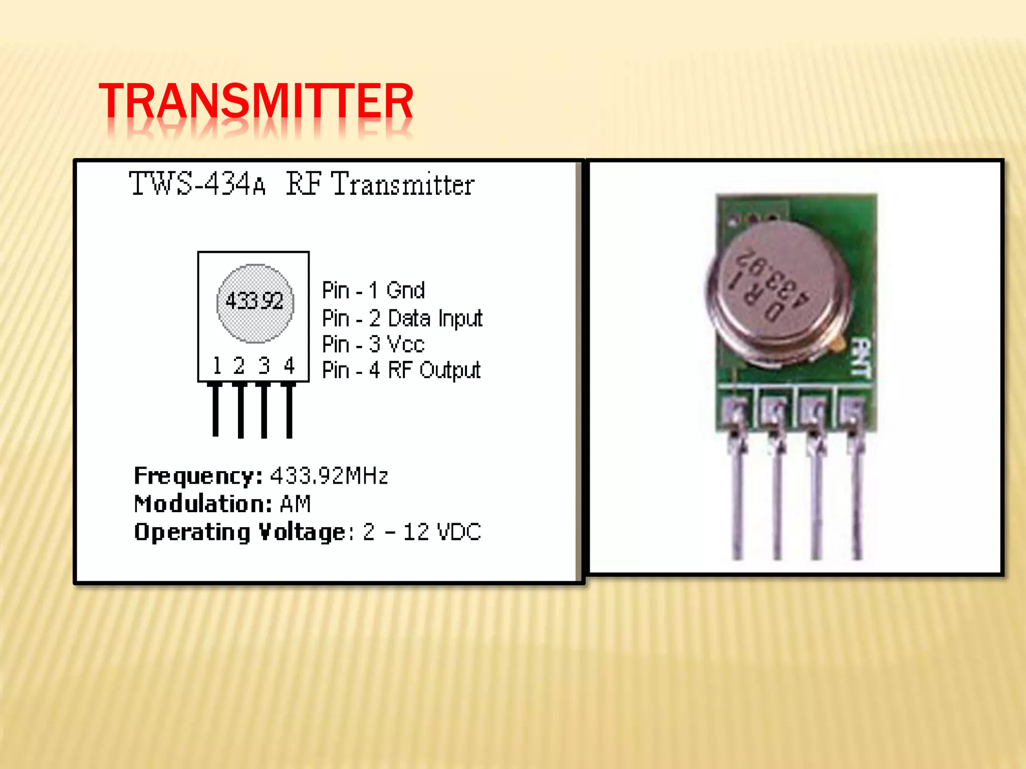
The parallax 433.92 MHZ RF transmitter allows users to easily
send serial data wirelessly .
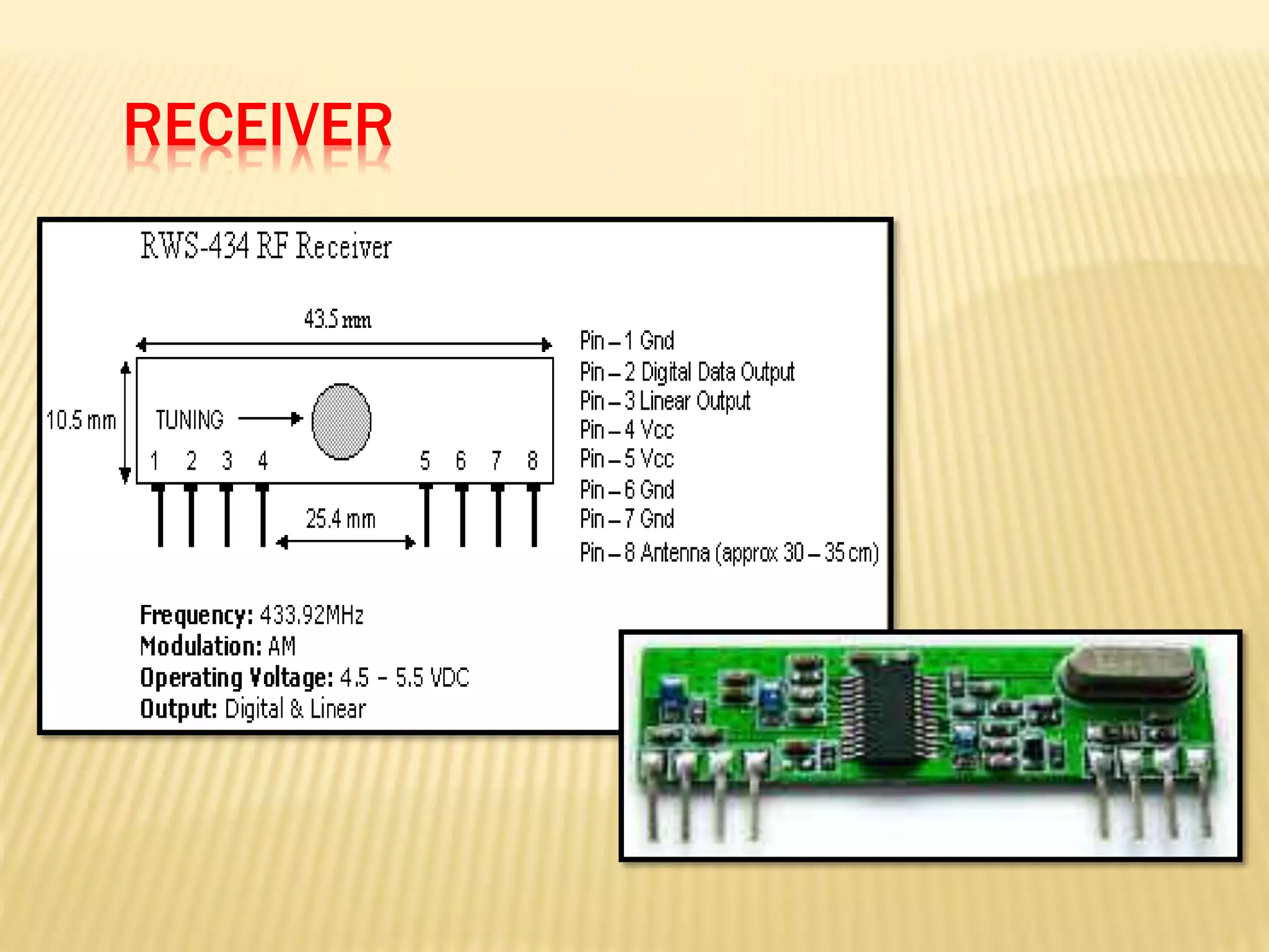
The RF transmitter paired with the matched RF receiver, reliable
wireless communication is as effortless.
3.
OVERVIEW
In cryptography,encryption is the process of transforming the information
using an algorithm . The result of this process is encrypted information.
Nowadays when more and more sensitive information is stored on
computers and transmitted over the Internet or other communication
means, we need to ensure information security and safety.
Sending sensitive messages, documents and files over the internet. Your
message is totally open to interception by anyone along the way – so
anybody - your ISP, your boss, etc. can read your message.
4.
Once yourdata has been encrypted, a person can not make
sense of your data without knowing the password (or figuring
it out).
Sophisticated software can make intelligent guesses of the
password to decrypt data. One easy way is with a database of
common passwords. A more difficult way is by analyzing the
encrypted data.
A longer password makes it more difficult for the entruders to
decrypt the data.
5.
RF communicationworks by creating electromagnetic
waves at a source and being able to pick up those
electromagnetic waves at a particular destination.
Higher frequencies result in shorter wavelengths. The
wavelength for a 900 MHz is longer than that of a
2.4 GHz.
Introduction to RF
The wavelength of an electromagnetic signal is
inversely proportional to the frequency; the higher the
frequency, the shorter the wavelength.
6.
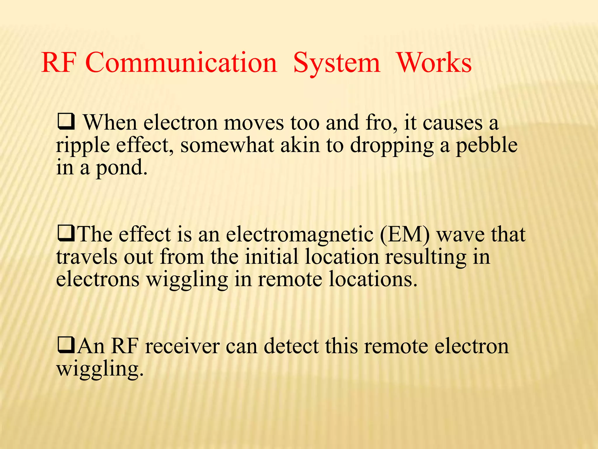
When electronmoves too and fro, it causes a
ripple effect, somewhat akin to dropping a pebble
in a pond.
The effect is an electromagnetic (EM) wave that
travels out from the initial location resulting in
electrons wiggling in remote locations.
An RF receiver can detect this remote electron
wiggling.
RF Communication System Works
7.
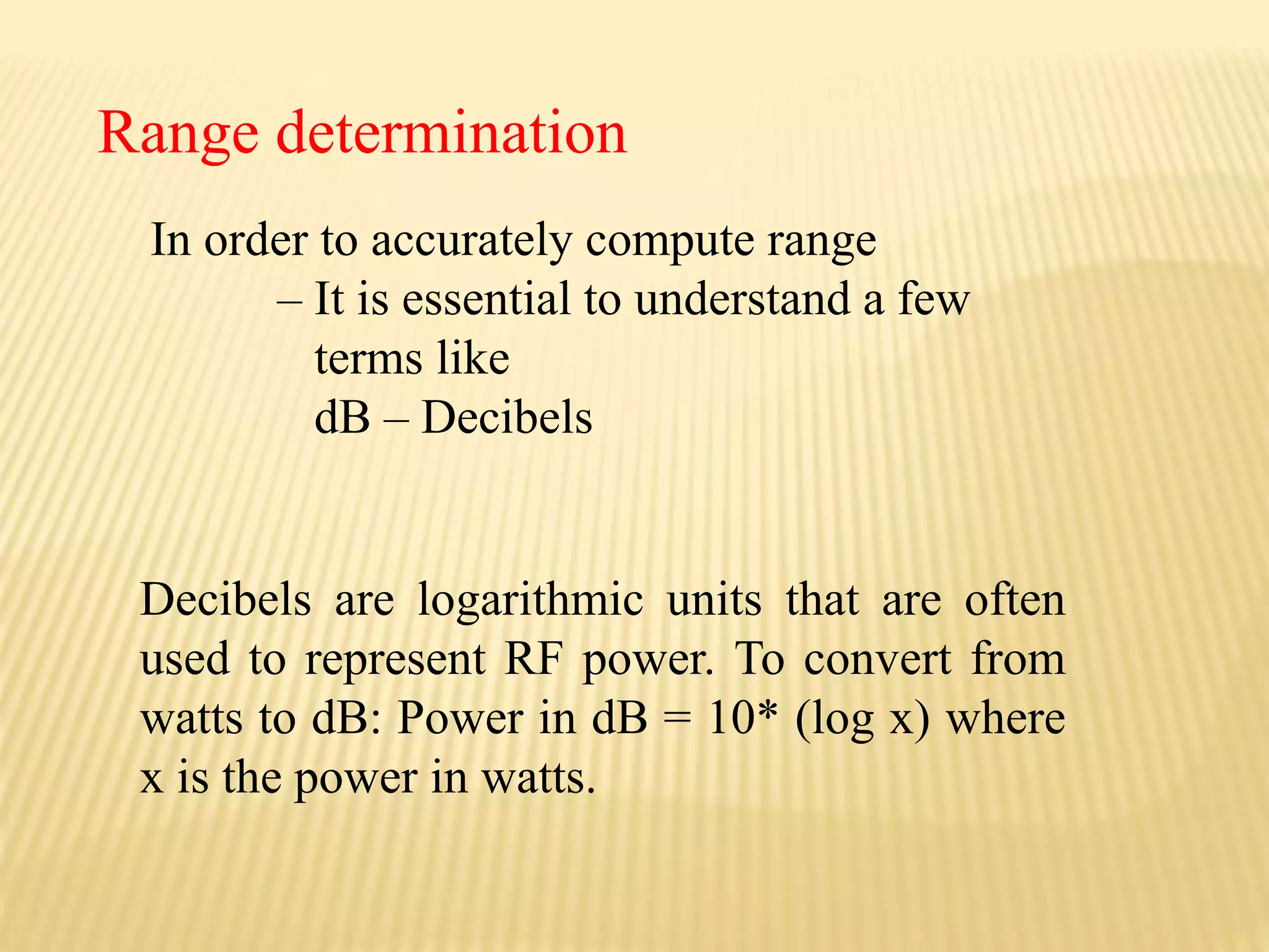
In order toaccurately compute range
– It is essential to understand a few
terms like
dB – Decibels
Range determination
Decibels are logarithmic units that are often
used to represent RF power. To convert from
watts to dB: Power in dB = 10* (log x) where
x is the power in watts.
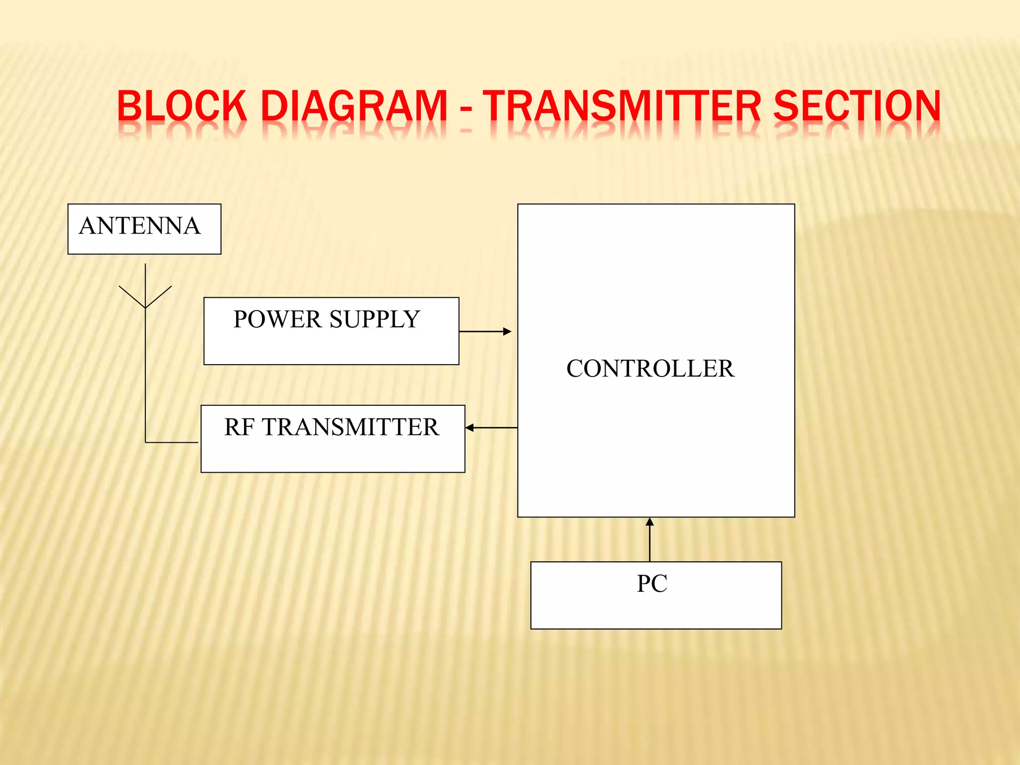
In this transmitterpart we use the MAX232N
for shifting the levels of the serial data to the
microcontroller .
RF Transmitter output is connected to the
antenna.
The data which is in the air is in analog form.
The RF modules used here are TWS-434 MHz
Transmitter, RWS-434 MHz Receiver .
12.
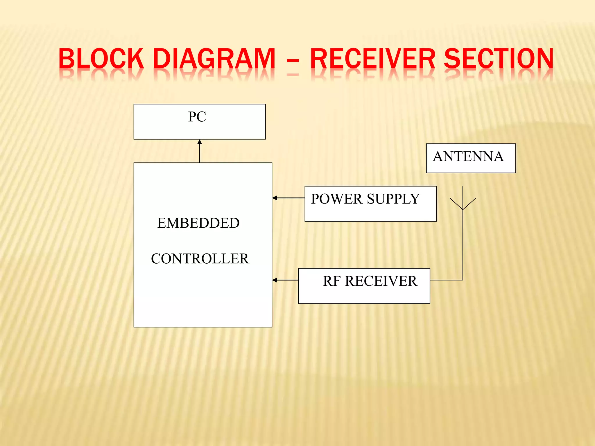
BLOCK DIAGRAM –RECEIVER SECTION
RF RECEIVER
POWER SUPPLY
EMBEDDED
CONTROLLER
PC
ANTENNA
At thereceiving end, the receiver receives
this analog form on a single data line and
passes this data to the microcontroller.
This project uses regulated 5V, 500mA
power supply.
In this receiver part we use the MAX232N for
shifting the levels of the serial data from
microcontroller .
15.
The namePIC initially referred to "Peripheral Interface Controller".
derived from the PIC1640,PIC is a family of Harvard architecture
microcontrollers.
The package type of this integrated circuits is DIP package. DIP stand
for Dual Inline Package for semiconductor IC
This IC works on just a 5V power supply adapter, 20MHz crystal
oscillator and 2 units of 33pF capacitors.
PICs are popular with developers ,alike due to their low cost, wide
availability ,free development tools and serial programming
INTRODUCTION TO PIC16F877A
MICROCONTROLLER
There are40 pins in PIC16F877A.
Most of the pins are for input and output, and arranged as 5 ports: A(5),
B(8),C(8), D(8) and E(3), giving a total of 32 I/O pins.
These all can operate as simple digital I/O pins, but most have more than one
function, and the mode of operation of each is selected by initializing various
control registers within the chip.
Ports A and E become ANALOG INPUTS by default (on power up or reset), so
they have to set up for digital I/O if required.
Port B is used for downloading the program to the chip flash ROM (RB6 and
RB7), and RB0 and RB4–RB7 can generate an interrupt.
Port C gives access to timers and serial ports.
Port D can be used as a slave port.
Port E providing the control pins for this function.
PIN DESCRIPTION
18.
Embedded Control Solutioncompany is the
manufacture of this PIC microcontrollers.
Microchips manufacture base-line, mid-range
and High-end controllers (12,14,16bit word
respectively)
PIC16F877A is a 16 bit controller
Microchip’s PIC 16F877A
19.
One ofthe easiest and most frequently used solutions to
the voltage differences for TTL/CMOS and RS-232 is
theMAX-232 chip from MAXIM semiconductors.
This chip converts 5-volts TTL/CMOS signal to a minimum of
+8 to-8volts.
Each level converter handles the conversion of two
TTL/CMOS lines .We will use the first for data transmit & receive
and the second for CTS/RTS handshaking.
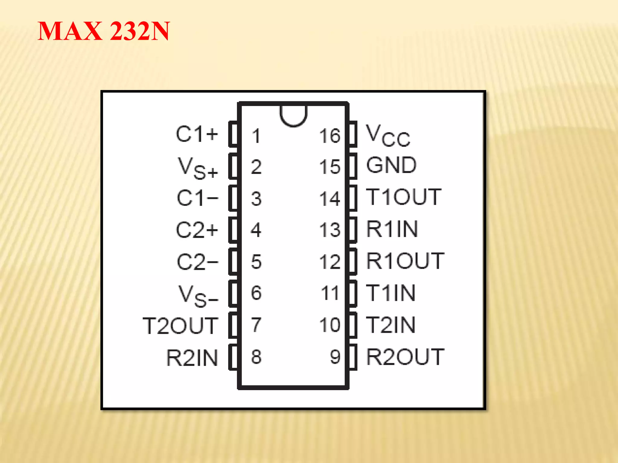
The MAX-232 is a 16-pin chip that has two complete RS-
232transreceivers. These chips work by using the capacitors to boost
the signal voltage levels to operate with in the RS-232 signal
definitions.
Introduction to MAX232N
Features of MAX232N
OperatesFrom a Single 5-V Power Supply
With 1.0-F Charge-Pump Capacitors
Operates Up To 120 Kbit/s
Two trans receivers
+/- 30v input levels
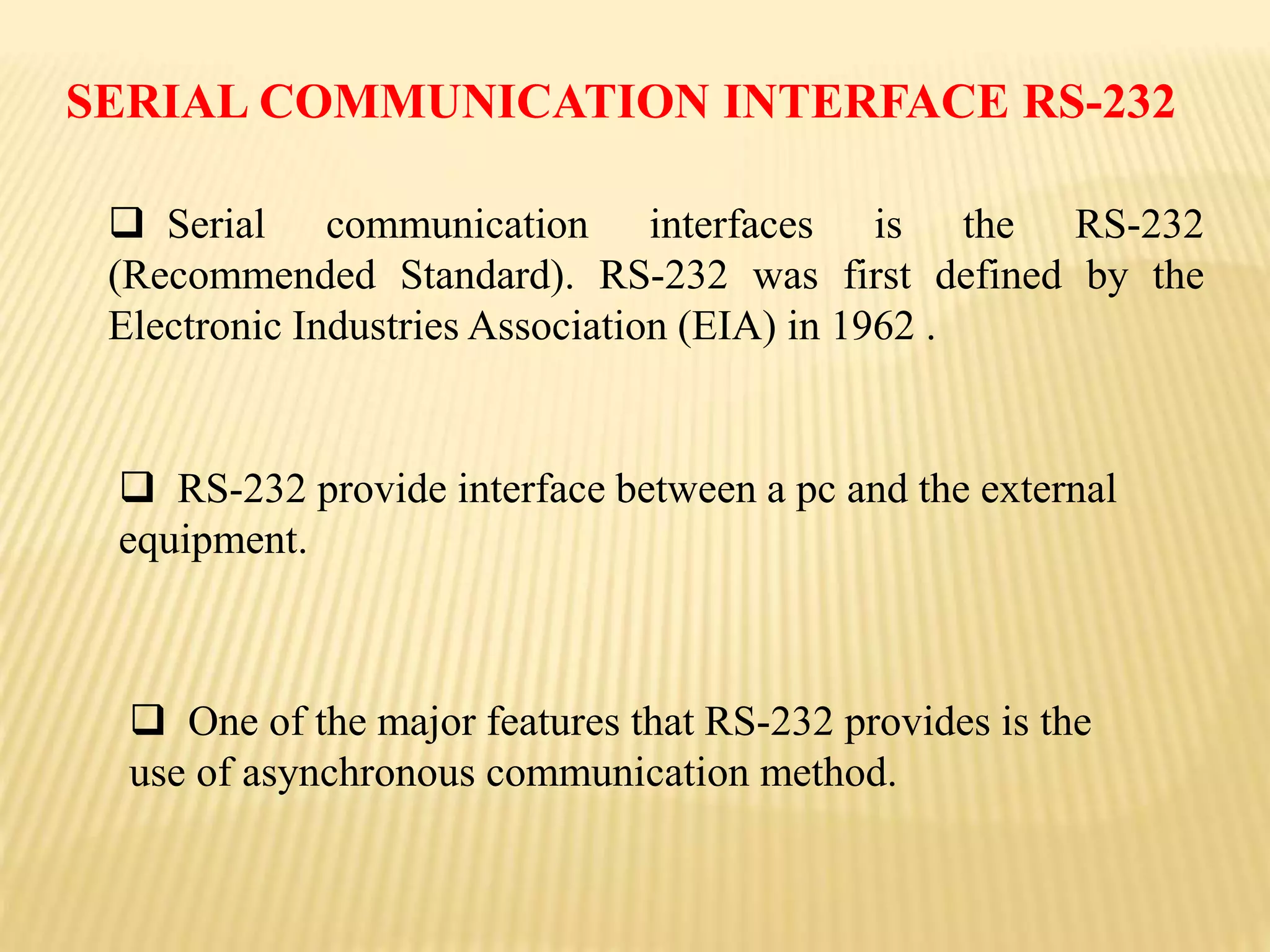
Serial communicationinterfaces is the RS-232
(Recommended Standard). RS-232 was first defined by the
Electronic Industries Association (EIA) in 1962 .
RS-232 provide interface between a pc and the external
equipment.
One of the major features that RS-232 provides is the
use of asynchronous communication method.
SERIAL COMMUNICATION INTERFACE RS-232
24.
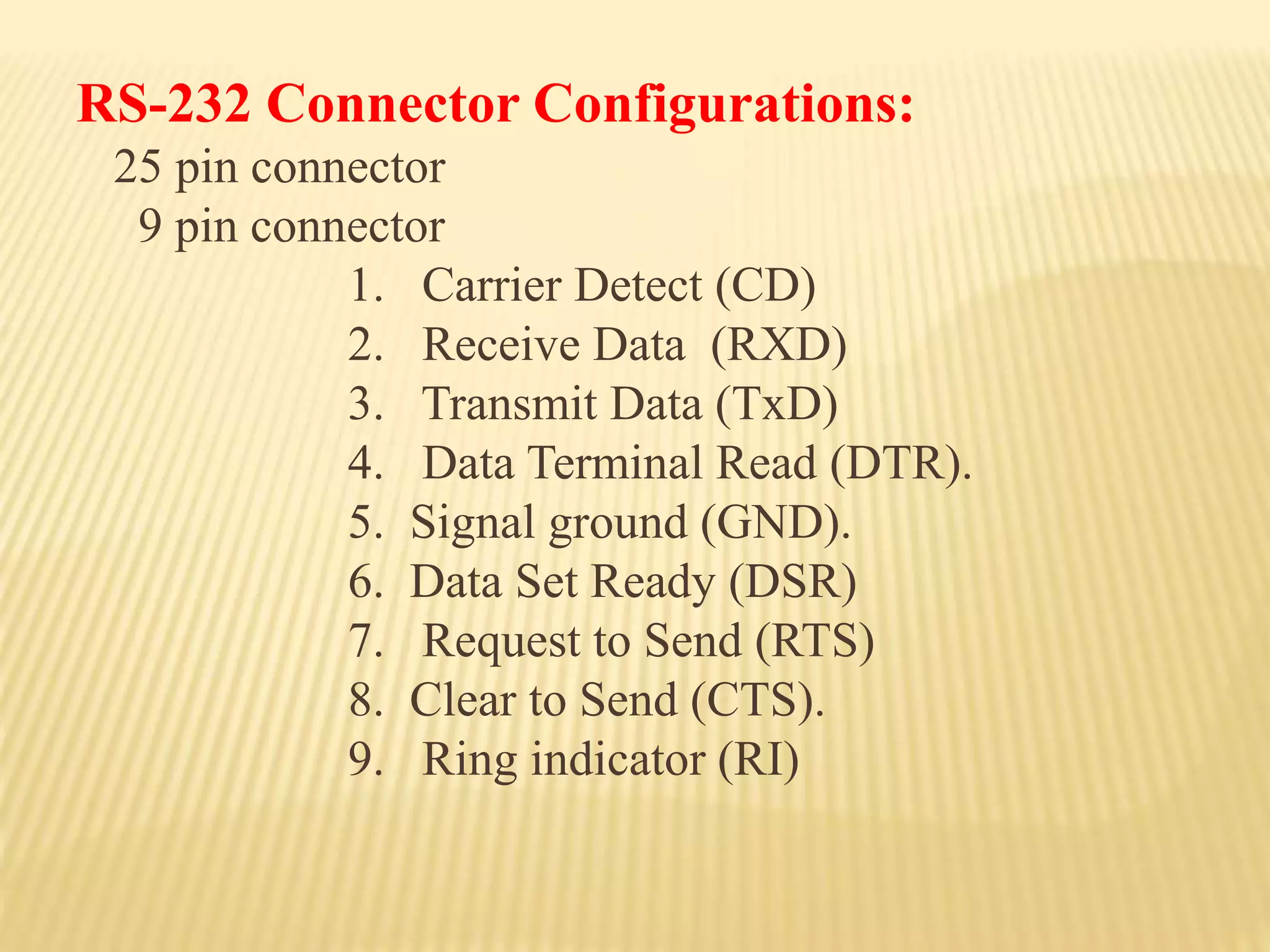
RS-232 Connector Configurations:
25pin connector
9 pin connector
1. Carrier Detect (CD)
2. Receive Data (RXD)
3. Transmit Data (TxD)
4. Data Terminal Read (DTR).
5. Signal ground (GND).
6. Data Set Ready (DSR)
7. Request to Send (RTS)
8. Clear to Send (CTS).
9. Ring indicator (RI)
25.
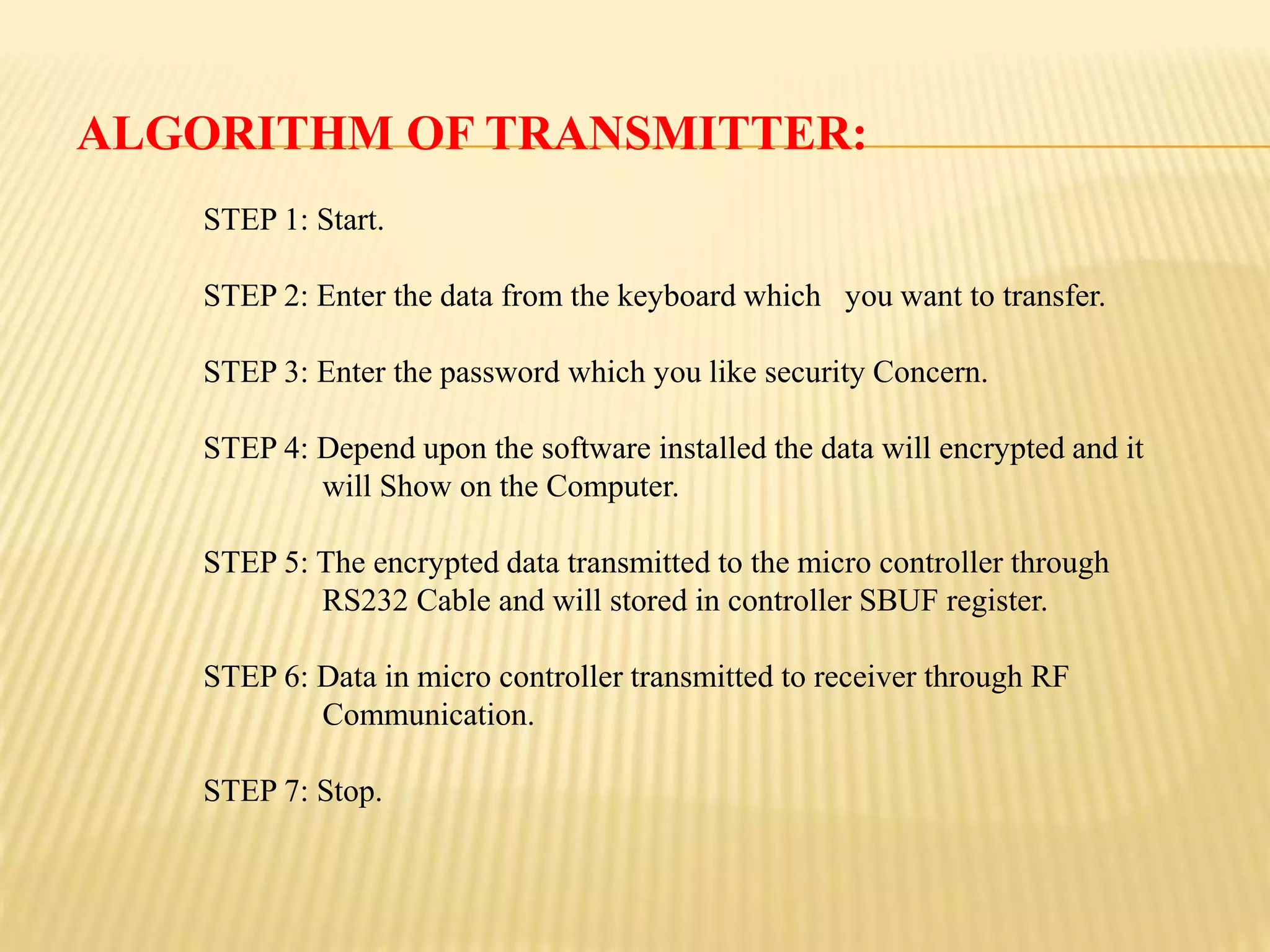
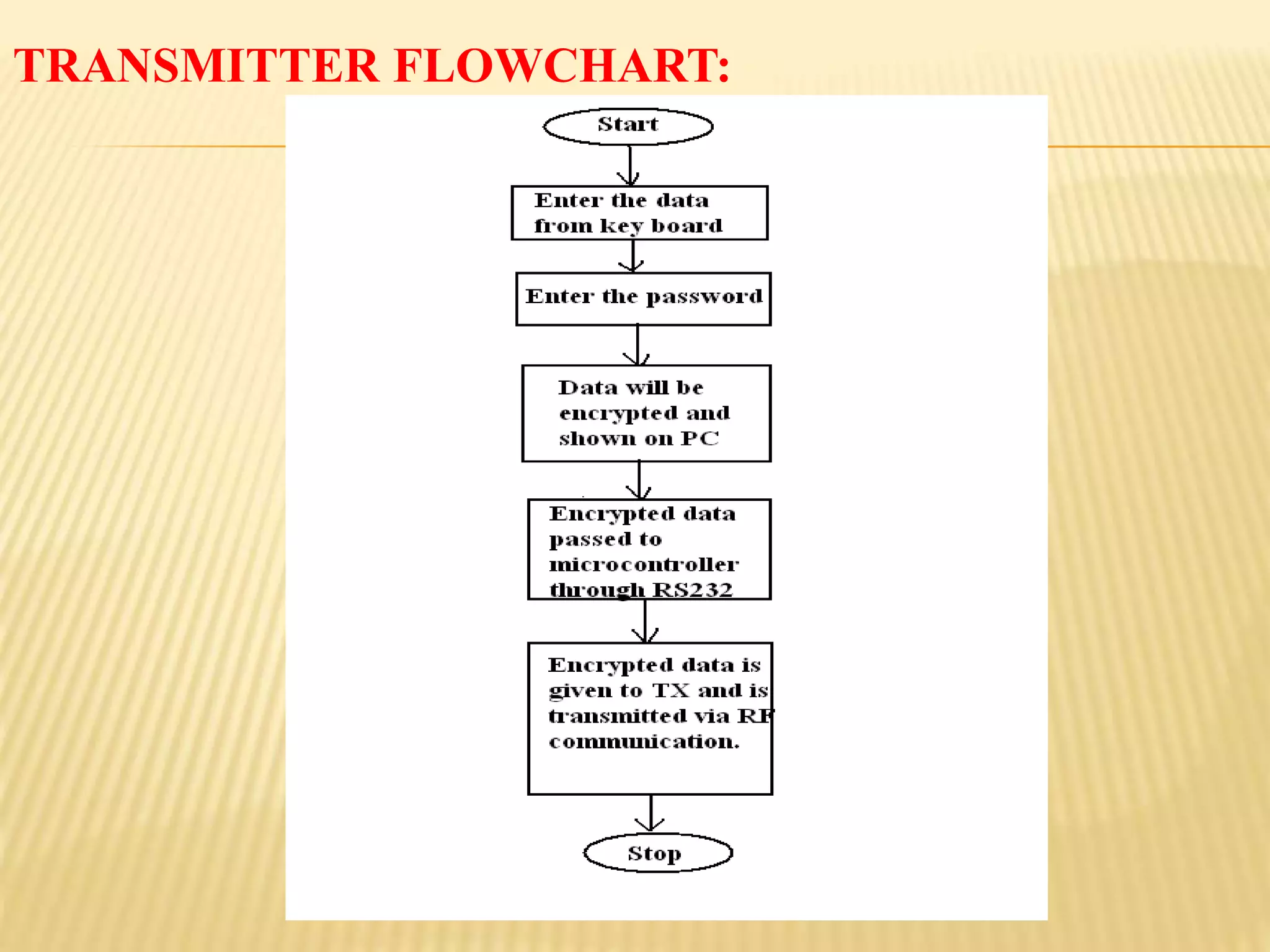
ALGORITHM OF TRANSMITTER:
STEP1: Start.
STEP 2: Enter the data from the keyboard which you want to transfer.
STEP 3: Enter the password which you like security Concern.
STEP 4: Depend upon the software installed the data will encrypted and it
will Show on the Computer.
STEP 5: The encrypted data transmitted to the micro controller through
RS232 Cable and will stored in controller SBUF register.
STEP 6: Data in micro controller transmitted to receiver through RF
Communication.
STEP 7: Stop.
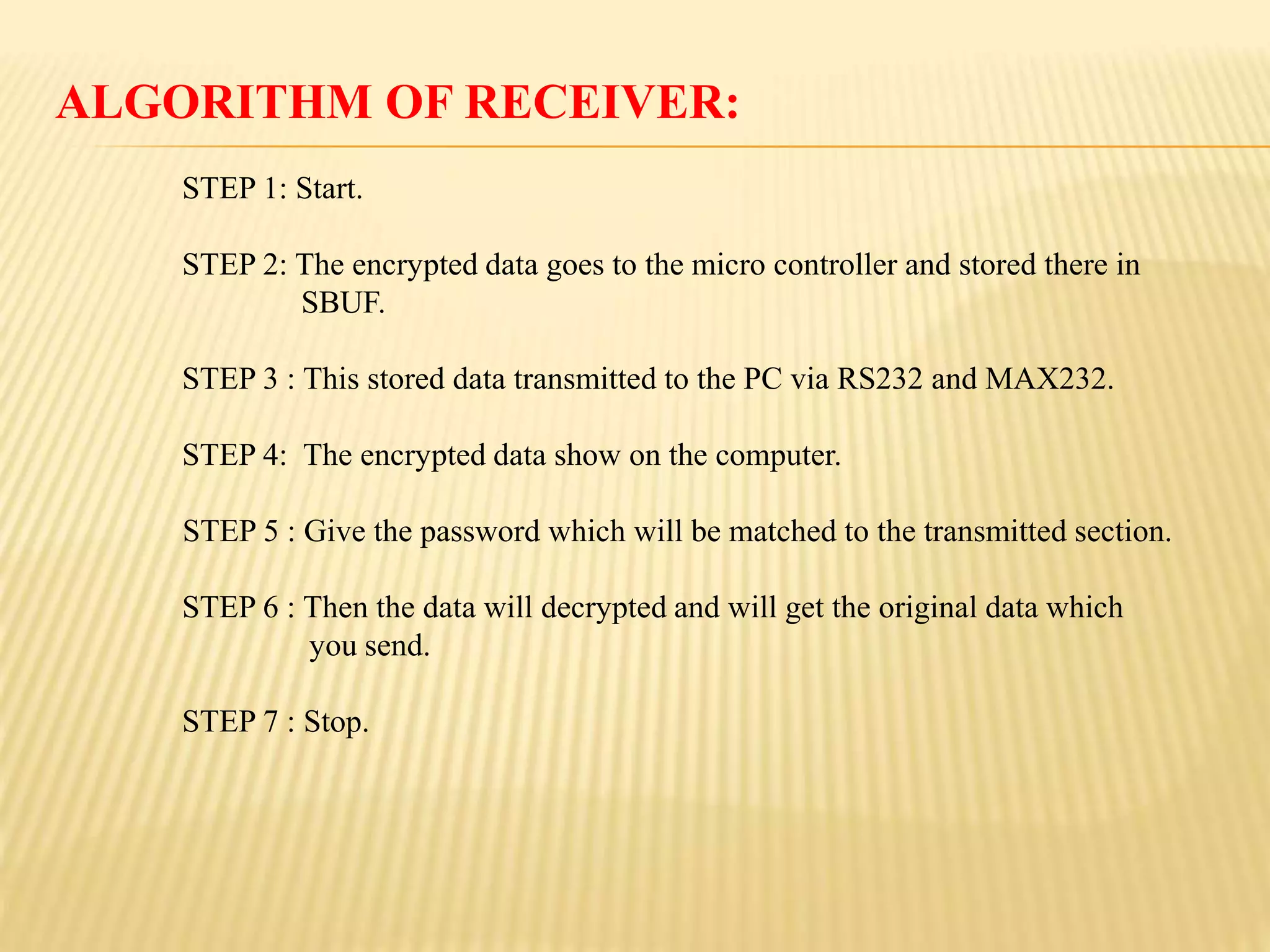
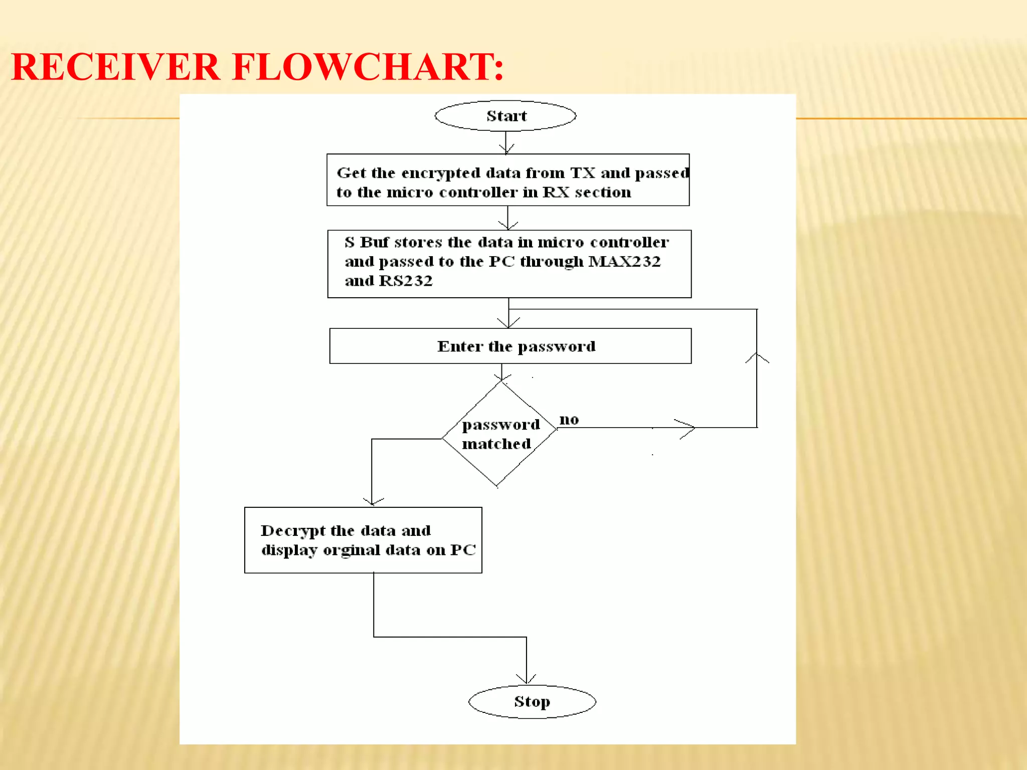
ALGORITHM OF RECEIVER:
STEP1: Start.
STEP 2: The encrypted data goes to the micro controller and stored there in
SBUF.
STEP 3 : This stored data transmitted to the PC via RS232 and MAX232.
STEP 4: The encrypted data show on the computer.
STEP 5 : Give the password which will be matched to the transmitted section.
STEP 6 : Then the data will decrypted and will get the original data which
you send.
STEP 7 : Stop.
ADVANTAGES
Security.
Noline of sight is required.
Speed of transmission.
Not as sensitive to weather/environmental conditions .
Easy to implement.
Unlimited data transfer.
LIMITATIONS:
• Since itis a wireless communication sometimes the
atmosphere may disturb the Signals this results data loss.
• Interference: communication devices using similar
frequencies - wireless Phones, scanners, wrist radios and
personal locators can interfere with Transmission.
•We have to use separate radio band, which may be
expensive
32.
CONCLUSION
Hence by thiswe can say that it is provided with a effective security for
data communication by designing standard algorithm for encryption and
decryption and this transmission will also includes the password which
provides additional security for the data.
This transmission includes the password so the users must and should
remember this and keep it as secret and the password will be any of
length we can use.
The work presented in this thesis provides a model for data “Secure
data transmission through RF communication” is used to provide the
security to the data.
The encrypted data looks like the garbage until it is decrypted. So, it is
not possible for any one to look over the data during the transmission.
33.
FUTURE SCOPE
Throughthis technique we can send any type of data with high
level of security, by making the modifications in i/p and o/p
devices.
This is embedded based so we can make our own algorithm in
micro controller for more security concern.
We can use these high level security transfer systems for banking ,
military and online shopping .
We can use the powerful antennas for longer communication.


![2[1].1 data transmission](https://cdn.slidesharecdn.com/ss_thumbnails/21-1-datatransmission-111203164944-phpapp01-thumbnail.jpg?width=640&height=640&fit=bounds)


