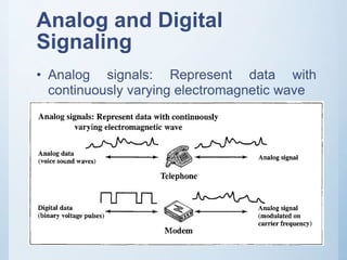
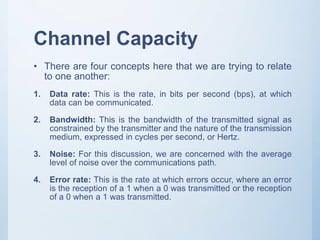
MOBILE
COMPUTING
&
WIRELESS
COMMUNICATION
Jay Nagar
+91-9601957620
www.jaynagarblog.wordpress.com
Introduction
• Wireless Comes of Age
• The Cellular Revolution
• The Global Cellular Network
• Broadband
• The Trouble With Wireless
Wireless Comes of Age
1. Transmission Fundamentals
• Transmission Fundamentals
• Provides a basic overview of transmission topics.
• Some data communications concepts
• Signaling techniques.
• Analog and Digital data transmission.
• Channel capacity,
• Transmission media, and the concept of multiplexing.
Outline
• Signals for Conveying Information
– Time Domain Concepts
– Frequency Domain Concepts
– Relationship between Data Rate and Bandwidth
• Analog and Digital Data Transmission
– Analog and Digital Data
– Analog and Digital Signaling
– Analog and Digital Transmission
• Channel Capacity
– Nyquist Bandwidth
– Shannon Capacity Formula
Outline
• Transmission Media
– Terrestrial Microwave
– Satellite Microwave
– Broadcast Radio
– Infrared
• Multiplexing
Signals for Conveying
Information
• We are concerned with electromagnetic signals.
• An electromagnetic signal is a function of time, but it can also
be expressed as a function of frequency;
• Time Domain Concepts:
• An electromagnetic signal can be either analog or digital.
• Analog signal is one in which the signal intensity varies in a
smooth fashion over time. In other words, there are no breaks
or discontinuities in the signal.
• Digital signal is one in which the signal intensity maintains a
constant level for some period of time and then changes to
another constant level.
Signals for Conveying
Information
Signals for Conveying
Information
• The effect of varying each of the three parameters.
In part (a) of the figure, the frequency is 1 Hz; thus
the period is T = 1 second
Signals for Conveying
Information
• Part (b) has the same frequency and phase but a
peak amplitude of 0.5. peak amplitude of 0.5.
Signals for Conveying
Information
• In part (c) we have f = 2, which is equivalent to T =
1/2.
Signals for Conveying
Information
• Part (d) shows the effect of a phase shift.
Signals for Conveying
Information
• There is a simple relationship between the two sine
waves, one in time and one in space.
• The wavelength of a signal is the distance
occupied by a single cycle, or, put another way,
the distance between two points of corresponding
phase of two consecutive cycles.
Signals for Conveying
Information
• Frequency Domain Concepts
• Relationship between Data Rate and
Bandwidth
– There is a direct relationship between the
information-carrying capacity of a signal and its
bandwidth: The greater the bandwidth, the higher
the information-carrying capacity.
Analog and Digital Data
Transmission
• The terms analog and digital correspond, roughly, to
continuous and discrete, respectively.
• These two terms are used frequently in data
communications in at least three contexts: data, signals,
and transmission.
• Data as entities that convey meaning, or information.
• Signals are electric or electromagnetic representations
of data.
• Transmission is the communication of data by the
propagation and processing of signals.
Analog and Digital Data
• Analog data take on continuous values in some
interval For example, voice and video are
continuously varying patterns of intensity.
• Digital data take on discrete values; examples are
text and integers.
• The most familiar example of analog data is audio,
which, in the form of sound waves, can be
perceived directly by human beings.
Analog and Digital
Signaling
• In communications system, data are propagated from one point to
another by means of electromagnetic signals.
• An analog signal is a continuously varying electromagnetic
wave that may be propagated over a variety of media, depending
on frequency; examples are copper wire media, such as twisted
pair and coaxial cable wireless media…
• A digital signal is a sequence of voltage pulses that may be
transmitted over a copper wire medium; for example, a constant
positive voltage level may represent binary 0 and a constant
negative voltage level may represent binary l.
Analog and Digital
Signaling
• Digital data can also be represented by analog
signals by use of a modem (modulator-
demodulator). The modem converts a series of
binary (two-valued) voltage pulses into an analog
signal by modulating a carrier frequency.
Analog and Digital
Signaling
• Analog signals: Represent data with
continuously varying electromagnetic wave
Analog and Digital
Signaling
• Digital signals: Represent data with
sequence of voltage pulses
Analog and Digital
Transmission
Analog and Digital
Transmission
• Analog transmission is a means of transmitting
analog signals without regard to their content; the
signals may represent analog data (e.g., voice) or
digital data (e.g., data that pass through a modem).
• To achieve longer distances, the analog
transmission system includes amplifiers that boost
the energy in the signal.
Analog and Digital
Transmission
• Digital transmission, in contrast, is concerned
with the content of the signal. We have
mentioned that a digital signal can be propagated
only a limited distance.
• To achieve greater distances, repeaters are used. A
repeater receives the digital signal, recovers the
pattern of ones and zeros, and retransmits a new
signal. Thus, the attenuation is overcome.
Channel Capacity
• A variety of impairments can distort or corrupt a
signal. A common impairment is noise.
• Noise is something that degrades signal quality.
• The maximum rate at which data can be transmitted
over a given communication path, or channel, under
given conditions is referred to as the channel
capacity.
Channel Capacity
• There are four concepts here that we are trying to relate
to one another:
1. Data rate: This is the rate, in bits per second (bps), at which
data can be communicated.
2. Bandwidth: This is the bandwidth of the transmitted signal as
constrained by the transmitter and the nature of the transmission
medium, expressed in cycles per second, or Hertz.
3. Noise: For this discussion, we are concerned with the average
level of noise over the communications path.
4. Error rate: This is the rate at which errors occur, where an error
is the reception of a 1 when a 0 was transmitted or the reception
of a 0 when a 1 was transmitted.
Channel Capacity - Nyquist
Bandwidth
• let us consider the case of a channel that is noise
free.
• Nyquist, states that if the rate of signal transmission is
2B, then a signal with frequencies no greater than B
is sufficient to carry the signal rate.
• C = 2B log2 M
– M is the number of discrete signal elements or voltage
levels.
– B is bandwidth
– For Example : M = 8, a value used with some modems, a
bandwidth of B = 3100 Hz yields
Shannon Capacity
• Nyquist's formula indicates that, all other things
being equal, doubling the bandwidth doubles the
data rate.
• Consider the relationship among data rate, noise,
and error rate.
Shannon Capacity
• The key parameter involved in this reasoning is the
signal-to-noise ratio (SNR, or S/N).
• This ratio is measured at a receiver.
• A high SNR will mean a high-quality signal.
• Shannon's result is that, the maximum channel capacity,
in bits per second, obeys the equation.
C = B log2(1 + SNR)
Transmission Media
• Physical path between transmitter and receiver.
• Can be classified as guided or unguided. In both cases,
communication is in the form of electromagnetic waves.
• In Guided media, the waves are guided along a solid
medium, such as copper twisted pair, copper coaxial
cable, or optical fiber.
• Unguided media, which provide a means of
transmitting electromagnetic signals but do not
guide them; The atmosphere and outer space are
examples
Transmission Media
• There are basically two types of configurations for
wireless transmission: directional and
omnidirectional.
• For the directional configuration, the transmitting
antenna puts out a focused electromagnetic beam;
the transmitting and receiving antennas must
therefore be carefully aligned.
• In the omnidirectional case, the transmitted signal
spreads out in all directions and can be received by
many antennas.
Transmission Media
• Three general ranges of frequencies are categories.
• Frequencies in the range of about 1 GHz (gigahertz =
109 Hz) to 100 GHz are referred to as microwave
frequencies. microwave is quite suitable for point-to-
point transmission.
• Frequencies in the range 30 MHz to 1 GHz are suitable
for omnidirectional applications. We refer to this range as
the radio range.
• Another important frequency range, for local
applications, is the infrared portion
• of the spectrum. This covers, roughly, from 3 X 10¹¹ to 2
X 1014 Hz.
Multiplexing
• To make efficient use of the transmission system, it
is desirable to carry multiple signals on a single
medium. This is referred to as multiplexing.
Multiplexing
• Two techniques for multiplexing in
telecommunications networks are in common use:
• Frequency division multiplexing (FDM)
• Time division multiplexing (TDM).
Multiplexing - FDM
• A number of signals can be carried simultaneously if
each signal is modulated onto a different carrier
frequency and the carrier frequencies are
sufficiently separated so that the bandwidths of
the signals do not overlap.
• the channels are separated by guard bands, which
are unused portions of the spectrum.
Multiplexing - TDM
• Multiple digital signals can be carried on a single
transmission path by interleaving portions of each
signal in time.
• The interleaving can be at the bit level or in blocks
of bytes or larger quantities.
Synchronous TDM System -
Transmitter
Synchronous TDM System -
Receiver

MOBILE COMPUTING and WIRELESS COMMUNICATION

  • 1.
  • 2.
    Introduction • Wireless Comesof Age • The Cellular Revolution • The Global Cellular Network • Broadband • The Trouble With Wireless
  • 4.
  • 5.
    1. Transmission Fundamentals •Transmission Fundamentals • Provides a basic overview of transmission topics. • Some data communications concepts • Signaling techniques. • Analog and Digital data transmission. • Channel capacity, • Transmission media, and the concept of multiplexing.
  • 6.
    Outline • Signals forConveying Information – Time Domain Concepts – Frequency Domain Concepts – Relationship between Data Rate and Bandwidth • Analog and Digital Data Transmission – Analog and Digital Data – Analog and Digital Signaling – Analog and Digital Transmission • Channel Capacity – Nyquist Bandwidth – Shannon Capacity Formula
  • 7.
    Outline • Transmission Media –Terrestrial Microwave – Satellite Microwave – Broadcast Radio – Infrared • Multiplexing
  • 8.
    Signals for Conveying Information •We are concerned with electromagnetic signals. • An electromagnetic signal is a function of time, but it can also be expressed as a function of frequency; • Time Domain Concepts: • An electromagnetic signal can be either analog or digital. • Analog signal is one in which the signal intensity varies in a smooth fashion over time. In other words, there are no breaks or discontinuities in the signal. • Digital signal is one in which the signal intensity maintains a constant level for some period of time and then changes to another constant level.
  • 9.
  • 10.
    Signals for Conveying Information •The effect of varying each of the three parameters. In part (a) of the figure, the frequency is 1 Hz; thus the period is T = 1 second
  • 11.
    Signals for Conveying Information •Part (b) has the same frequency and phase but a peak amplitude of 0.5. peak amplitude of 0.5.
  • 12.
    Signals for Conveying Information •In part (c) we have f = 2, which is equivalent to T = 1/2.
  • 13.
    Signals for Conveying Information •Part (d) shows the effect of a phase shift.
  • 14.
    Signals for Conveying Information •There is a simple relationship between the two sine waves, one in time and one in space. • The wavelength of a signal is the distance occupied by a single cycle, or, put another way, the distance between two points of corresponding phase of two consecutive cycles.
  • 15.
    Signals for Conveying Information •Frequency Domain Concepts • Relationship between Data Rate and Bandwidth – There is a direct relationship between the information-carrying capacity of a signal and its bandwidth: The greater the bandwidth, the higher the information-carrying capacity.
  • 16.
    Analog and DigitalData Transmission • The terms analog and digital correspond, roughly, to continuous and discrete, respectively. • These two terms are used frequently in data communications in at least three contexts: data, signals, and transmission. • Data as entities that convey meaning, or information. • Signals are electric or electromagnetic representations of data. • Transmission is the communication of data by the propagation and processing of signals.
  • 17.
    Analog and DigitalData • Analog data take on continuous values in some interval For example, voice and video are continuously varying patterns of intensity. • Digital data take on discrete values; examples are text and integers. • The most familiar example of analog data is audio, which, in the form of sound waves, can be perceived directly by human beings.
  • 18.
    Analog and Digital Signaling •In communications system, data are propagated from one point to another by means of electromagnetic signals. • An analog signal is a continuously varying electromagnetic wave that may be propagated over a variety of media, depending on frequency; examples are copper wire media, such as twisted pair and coaxial cable wireless media… • A digital signal is a sequence of voltage pulses that may be transmitted over a copper wire medium; for example, a constant positive voltage level may represent binary 0 and a constant negative voltage level may represent binary l.
  • 19.
    Analog and Digital Signaling •Digital data can also be represented by analog signals by use of a modem (modulator- demodulator). The modem converts a series of binary (two-valued) voltage pulses into an analog signal by modulating a carrier frequency.
  • 20.
    Analog and Digital Signaling •Analog signals: Represent data with continuously varying electromagnetic wave
  • 21.
    Analog and Digital Signaling •Digital signals: Represent data with sequence of voltage pulses
  • 22.
  • 23.
    Analog and Digital Transmission •Analog transmission is a means of transmitting analog signals without regard to their content; the signals may represent analog data (e.g., voice) or digital data (e.g., data that pass through a modem). • To achieve longer distances, the analog transmission system includes amplifiers that boost the energy in the signal.
  • 24.
    Analog and Digital Transmission •Digital transmission, in contrast, is concerned with the content of the signal. We have mentioned that a digital signal can be propagated only a limited distance. • To achieve greater distances, repeaters are used. A repeater receives the digital signal, recovers the pattern of ones and zeros, and retransmits a new signal. Thus, the attenuation is overcome.
  • 25.
    Channel Capacity • Avariety of impairments can distort or corrupt a signal. A common impairment is noise. • Noise is something that degrades signal quality. • The maximum rate at which data can be transmitted over a given communication path, or channel, under given conditions is referred to as the channel capacity.
  • 26.
    Channel Capacity • Thereare four concepts here that we are trying to relate to one another: 1. Data rate: This is the rate, in bits per second (bps), at which data can be communicated. 2. Bandwidth: This is the bandwidth of the transmitted signal as constrained by the transmitter and the nature of the transmission medium, expressed in cycles per second, or Hertz. 3. Noise: For this discussion, we are concerned with the average level of noise over the communications path. 4. Error rate: This is the rate at which errors occur, where an error is the reception of a 1 when a 0 was transmitted or the reception of a 0 when a 1 was transmitted.
  • 27.
    Channel Capacity -Nyquist Bandwidth • let us consider the case of a channel that is noise free. • Nyquist, states that if the rate of signal transmission is 2B, then a signal with frequencies no greater than B is sufficient to carry the signal rate. • C = 2B log2 M – M is the number of discrete signal elements or voltage levels. – B is bandwidth – For Example : M = 8, a value used with some modems, a bandwidth of B = 3100 Hz yields
  • 28.
    Shannon Capacity • Nyquist'sformula indicates that, all other things being equal, doubling the bandwidth doubles the data rate. • Consider the relationship among data rate, noise, and error rate.
  • 29.
    Shannon Capacity • Thekey parameter involved in this reasoning is the signal-to-noise ratio (SNR, or S/N). • This ratio is measured at a receiver. • A high SNR will mean a high-quality signal. • Shannon's result is that, the maximum channel capacity, in bits per second, obeys the equation. C = B log2(1 + SNR)
  • 30.
    Transmission Media • Physicalpath between transmitter and receiver. • Can be classified as guided or unguided. In both cases, communication is in the form of electromagnetic waves. • In Guided media, the waves are guided along a solid medium, such as copper twisted pair, copper coaxial cable, or optical fiber. • Unguided media, which provide a means of transmitting electromagnetic signals but do not guide them; The atmosphere and outer space are examples
  • 31.
    Transmission Media • Thereare basically two types of configurations for wireless transmission: directional and omnidirectional. • For the directional configuration, the transmitting antenna puts out a focused electromagnetic beam; the transmitting and receiving antennas must therefore be carefully aligned. • In the omnidirectional case, the transmitted signal spreads out in all directions and can be received by many antennas.
  • 32.
    Transmission Media • Threegeneral ranges of frequencies are categories. • Frequencies in the range of about 1 GHz (gigahertz = 109 Hz) to 100 GHz are referred to as microwave frequencies. microwave is quite suitable for point-to- point transmission. • Frequencies in the range 30 MHz to 1 GHz are suitable for omnidirectional applications. We refer to this range as the radio range. • Another important frequency range, for local applications, is the infrared portion • of the spectrum. This covers, roughly, from 3 X 10¹¹ to 2 X 10¹⁴ Hz.
  • 33.
    Multiplexing • To makeefficient use of the transmission system, it is desirable to carry multiple signals on a single medium. This is referred to as multiplexing.
  • 34.
    Multiplexing • Two techniquesfor multiplexing in telecommunications networks are in common use: • Frequency division multiplexing (FDM) • Time division multiplexing (TDM).
  • 35.
    Multiplexing - FDM •A number of signals can be carried simultaneously if each signal is modulated onto a different carrier frequency and the carrier frequencies are sufficiently separated so that the bandwidths of the signals do not overlap. • the channels are separated by guard bands, which are unused portions of the spectrum.
  • 36.
    Multiplexing - TDM •Multiple digital signals can be carried on a single transmission path by interleaving portions of each signal in time. • The interleaving can be at the bit level or in blocks of bytes or larger quantities.
  • 37.
  • 38.