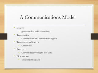
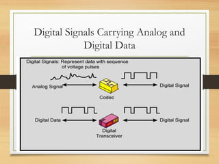
Data Communications
By : Ambesh Singh
s/w Er. MANTRA
A Communications Model
• Source
• generates data to be transmitted
• Transmitter
• Converts data into transmittable signals
• Transmission System
• Carries data
• Receiver
• Converts received signal into data
• Destination
• Takes incoming data
Simplified Communications Model -
Diagram
Simplified Data Communications
Model
• segments between entities on each connection
Key points
• All forms of information can be represented by
electromagnetic signals. Based on transmission medium
and the comm. environment, either analog or digital
signals can be used
• Any EM signal is made up of a # of constituent
frequencies -> bandwidth of the signal
• Transmission impairment: attenuation, delay distortion,
noise, etc.
• Design factors: signal bw, data rate of digital information,
noise level, error rate.
Terminology (1)
• Transmitter
• Receiver
• Medium
• Guided medium
• e.g. twisted pair, optical fiber, coaxial cable
• Unguided medium
• e.g. air, water, vacuum
Terminology (2)
• Direct link
• No intermediate devices
• Point-to-point
• Direct link
• Only 2 devices share link
• Multi-point
• More than two devices share the link
Terminology (3)
• Simplex
• One direction
• e.g. Television
• Half duplex
• Either direction, but only one way at a time
• e.g. police radio
• Full duplex
• Both directions at the same time
• e.g. telephone
Frequency, Spectrum and Bandwidth
• Time domain concepts
• Analog signal
• Various in a smooth way over time, e.g, speech
• Digital signal
• Maintains a constant level then changes to another constant
level, e.g., binary 1s and 0s
• Periodic signal
• Pattern repeated over time
• Aperiodic signal
• Pattern not repeated over time
Analogue & Digital Signals
Periodic
Signals
Sine Wave
• Peak Amplitude (A)
• maximum strength of signal
• volts
• Frequency (f)
• Rate of change of signal
• Hertz (Hz) or cycles per second
• Period = time for one repetition (T)
• T = 1/f
• Phase (φ)
• Relative position in time
• Sine waves are important building blocks for other signals.
Varying Sine Waves
s(t) = A sin(2πft +Φ)
Wavelength
• Distance occupied by one cycle
• Distance between two points of corresponding phase
in two consecutive cycles
• λ
• Assuming signal velocity v
• λ = vT
• λf = v =c in free space
• c = 3*108
ms-1
(speed of light in free space)
Frequency Domain Concepts
• Signal usually made up of many frequencies
• Components are sine waves
• Can be shown (Fourier analysis) that any signal is
made up of component sine waves
• Can plot frequency domain functions
Addition of
Frequency Components
(T=1/f)
This is a time-domain
illustration.
Frequency
Domain
Representations
Spectrum & Bandwidth
• Spectrum
• range of frequencies contained in signal
• Absolute bandwidth
• width of spectrum
• Effective bandwidth
• Often just bandwidth
• Narrow band of frequencies containing most of the energy
• DC Component
• Component of zero frequency
Signal with DC Component
Data Rate and Bandwidth
• Any transmission system has a limited band of
frequencies
• This limits the data rate that can be carried
• We will see two limits later
Analog and Digital Data
Transmission
• Data
• Entities that convey meaning
• Signals
• Electric or electromagnetic representations of data
• Transmission
• Communication of data by propagation and processing of
signals
Analog and Digital Data
• Analog
• Continuous values within some interval
• e.g. sound, video
• Digital
• Discrete values
• e.g. text, integers
Analog and Digital Signals
• Means by which data are propagated
• Analog
• Continuously variable
• Various media
• wire, fiber optic, space
• Speech bandwidth 100Hz to 7kHz
• Telephone bandwidth 300Hz to 3400Hz
• Video bandwidth 4MHz
• Digital
• Use two DC components
Advantages & Disadvantages
of Digital
• Cheaper
• Less susceptible to noise
• Greater attenuation
• Pulses become rounded and smaller
• Leads to loss of information
Attenuation of Digital Signals
Binary Digital Data
• From computer terminals etc.
• Two dc components
• Bandwidth depends on data rate
Data and Signals
• Usually use digital signals for digital data and analog
signals for analog data
• Can use analog signal to carry digital data
• Modem
• Can use digital signal to carry analog data
• Compact Disc audio
Analog Signals Carrying Analog and
Digital Data
Digital Signals Carrying Analog and
Digital Data
Analog Transmission
• Analog signal transmitted without regard to content
• May be analog or digital data
• Attenuated over distance
• Use amplifiers to boost signal
• Also amplifies noise
Digital Transmission
• Concerned with content
• Integrity endangered by noise, attenuation etc.
• Repeaters used
• Repeater receives signal
• Extracts bit pattern
• Retransmits
• Attenuation is overcome
• Noise is not amplified
Advantages of Digital Transmission
• Digital technology
• Low cost LSI/VLSI technology
• Data integrity
• Longer distances over lower quality lines
• Capacity utilization
• High bandwidth links economical
• High degree of multiplexing easier with digital techniques
• Security & Privacy
• Encryption
• Integration
• Can treat analog and digital data similarly
Transmission Impairments
• Signal received may differ from signal transmitted
• Analog - degradation of signal quality
• Digital - bit errors
• Caused by
• Attenuation and attenuation distortion
• Delay distortion
• Noise
Attenuation
• Signal strength falls off with distance
• Depends on medium
• Received signal strength:
• must be enough to be detected
• must be sufficiently higher than noise to be received without error
• Attenuation is an increasing function of frequency
Delay Distortion
• Only in guided media
• Propagation velocity varies with frequency
Noise (1)
• Additional signals inserted between transmitter and
receiver
• Thermal
• Due to thermal agitation of electrons
• Uniformly distributed
• White noise
• Intermodulation
• Signals that are the sum and difference of original frequencies
sharing a medium
Noise (2)
• Crosstalk
• A signal from one line is picked up by another
• Impulse
• Irregular pulses or spikes
• e.g. External electromagnetic interference
• Short duration
• High amplitude
Decibels
• Decibel is a measure of the ratio between two signal levels
• Reason to use decibels
• Signal strength often falls off exponentially, so loss is easily expressed in
terms of the decibel
• Net gain/loss in a cascaded transmission path can be calculated with
simple addition and subtraction.
in
out
dB
P
P
G 10log10=
Channel Capacity
• Data rate
• In bits per second
• Rate at which data can be communicated
• Bandwidth
• In cycles per second of Hertz
• Constrained by transmitter and medium
Nyquist Bandwidth
• If rate of signal transmission is 2B then signal with
frequencies no greater than B is sufficient to carry signal
rate
• Given bandwidth B, highest signal rate is 2B
• Given binary signal, data rate supported by B Hz is 2B
bps
• Can be increased by using M signal levels
• C= 2B log2M
• Noise-free channel
Shannon Capacity Formula
• Consider data rate, noise and error rate
• Faster data rate shortens each bit so burst of noise affects
more bits
• At given noise level, high data rate means higher error rate
• Signal to noise ratio (SNR) (in decibels)
• SNRdb
=
10 log10(signal/noise)
• Capacity C=B log2(1+SNR)
• This is error free capacity
Transmission Media: Overview
• Guided - wire
• Unguided - wireless
• Characteristics and quality determined by medium and
signal
• For guided, the medium is more important
• For unguided, the bandwidth produced by the antenna is
more important
• Key concerns are data rate and distance
Design Factors
• Bandwidth
• Higher bandwidth gives higher data rate
• Transmission impairments
• Attenuation
• Interference
• Number of receivers
• In guided media
• More receivers (multi-point) introduce more attenuation
Guided Transmission Media
• Twisted Pair
• Coaxial cable
• Optical fiber
Transmission Characteristics of Guided
Media
  Frequenc
y Range
Typical
Attenuati
on
Typical
Delay
Repeater
Spacing
Twisted
pair (with
loading)
0 to 3.5
kHz
0.2 dB/km
@ 1 kHz
50 µs/km 2 km
Twisted
pairs
(multi-pair
cables)
0 to 1 MHz 0.7 dB/km
@ 1 kHz
5 µs/km 2 km
Coaxial
cable
0 to 500
MHz
7 dB/km @
10 MHz
4 µs/km 1 to 9 km
Optical
fiber
186 to 370
THz
0.2 to 0.5
dB/km
5 µs/km 40 km
Twisted Pair
Twisted Pair - Applications
• Most common medium
• Telephone network
• Between house and local exchange (subscriber loop)
• Within buildings
• To private branch exchange (PBX)
• For local area networks (LAN)
• 10Mbps or 100Mbps
Twisted Pair - Pros and Cons
• Cheap
• Easy to work with
• Low data rate
• Short range
Twisted Pair - Transmission
Characteristics
• Analog
• Amplifiers every 5km to 6km
• Digital
• Use either analog or digital signals
• repeater every 2km or 3km
• Limited distance
• Limited bandwidth (1MHz)
• Limited data rate (100MHz)
• Susceptible to interference and noise
Unshielded and Shielded TP
• Unshielded Twisted Pair (UTP)
• Ordinary telephone wire
• Cheapest
• Easiest to install
• Suffers from external EM interference
• Shielded Twisted Pair (STP)
• Metal braid or sheathing that reduces interference
• More expensive
• Harder to handle (thick, heavy)
UTP Categories
• Cat 3
• up to 16MHz
• Voice grade found in most offices
• Twist length of 7.5 cm to 10 cm
• Cat 4
• up to 20 MHz
• Cat 5
• up to 100MHz
• Commonly pre-installed in new office buildings
• Twist length 0.6 cm to 0.85 cm
Coaxial Cable
Coaxial Cable Applications
• Most versatile medium
• Television distribution
• Ariel to TV
• Cable TV
• Long distance telephone transmission
• Can carry 10,000 voice calls simultaneously
• Being replaced by fiber optic
• Short distance computer systems links
• Local area networks
Coaxial Cable - Transmission
Characteristics
• Analog
• Amplifiers every few km
• Closer if higher frequency
• Up to 500MHz
• Digital
• Repeater every 1km
• Closer for higher data rates
Optical Fiber
Optical Fiber - Benefits
• Greater capacity
• Data rates of hundreds of Gbps
• Smaller size & weight
• Lower attenuation
• Electromagnetic isolation
• Greater repeater spacing
• 10s of km at least
Optical Fiber - Applications
• Long-haul trunks
• Metropolitan trunks
• Rural exchange trunks
• Subscriber loops
• LANs
Optical Fiber - Transmission
Characteristics
• Act as wave guide for 1014
to 1015
Hz
• Portions of infrared and visible spectrum
• Light Emitting Diode (LED)
• Cheaper
• Wider operating temp range
• Last longer
• Injection Laser Diode (ILD)
• More efficient
• Greater data rate
• Wavelength Division Multiplexing
Wireless Transmission Frequencies
• 2GHz to 40GHz
• Microwave
• Highly directional
• Point to point
• Satellite
• 30MHz to 1GHz
• Omnidirectional
• Broadcast radio
• 3 x 10¹¹
Hz to 2 x 10¹⁴
Hz
• Infrared
• Local
Antennas
• Electrical conductor (or system of..) used to radiate electromagnetic energy
or collect electromagnetic energy
• Transmission
• Radio frequency energy from transmitter
• Converted to electromagnetic energy
• By antenna
• Radiated into surrounding environment
• Reception
• Electromagnetic energy impinging on antenna
• Converted to radio frequency electrical energy
• Fed to receiver
• Same antenna often used for both
Radiation Pattern
• Power radiated in all directions
• Not same performance in all directions
• Isotropic antenna is (theoretical) point in space
• Radiates in all directions equally
• Gives spherical radiation pattern
Terrestrial Microwave
• Parabolic dish
• Focused beam
• Line of sight
• Long haul telecommunications
• Higher frequencies give higher data rates
Satellite Microwave
• Satellite is relay station
• Satellite receives on one frequency, amplifies or repeats
signal and transmits on another frequency
• Requires geo-stationary orbit
• Height of 35,784km
• Television
• Long distance telephone
• Private business networks
Satellite Point to Point Link
Satellite Broadcast Link
Broadcast Radio
• Omnidirectional
• FM radio
• UHF and VHF television
• Line of sight
• Suffers from multipath interference
• Reflections
Infrared
• Modulate noncoherent infrared light
• Line of sight (or reflection)
• Blocked by walls
• e.g. TV remote control, IRD port

Data communication

  • 1.
    Data Communications By :Ambesh Singh s/w Er. MANTRA
  • 2.
    A Communications Model •Source • generates data to be transmitted • Transmitter • Converts data into transmittable signals • Transmission System • Carries data • Receiver • Converts received signal into data • Destination • Takes incoming data
  • 3.
  • 4.
    Simplified Data Communications Model •segments between entities on each connection
  • 5.
    Key points • Allforms of information can be represented by electromagnetic signals. Based on transmission medium and the comm. environment, either analog or digital signals can be used • Any EM signal is made up of a # of constituent frequencies -> bandwidth of the signal • Transmission impairment: attenuation, delay distortion, noise, etc. • Design factors: signal bw, data rate of digital information, noise level, error rate.
  • 6.
    Terminology (1) • Transmitter •Receiver • Medium • Guided medium • e.g. twisted pair, optical fiber, coaxial cable • Unguided medium • e.g. air, water, vacuum
  • 7.
    Terminology (2) • Directlink • No intermediate devices • Point-to-point • Direct link • Only 2 devices share link • Multi-point • More than two devices share the link
  • 8.
    Terminology (3) • Simplex •One direction • e.g. Television • Half duplex • Either direction, but only one way at a time • e.g. police radio • Full duplex • Both directions at the same time • e.g. telephone
  • 9.
    Frequency, Spectrum andBandwidth • Time domain concepts • Analog signal • Various in a smooth way over time, e.g, speech • Digital signal • Maintains a constant level then changes to another constant level, e.g., binary 1s and 0s • Periodic signal • Pattern repeated over time • Aperiodic signal • Pattern not repeated over time
  • 10.
  • 11.
  • 12.
    Sine Wave • PeakAmplitude (A) • maximum strength of signal • volts • Frequency (f) • Rate of change of signal • Hertz (Hz) or cycles per second • Period = time for one repetition (T) • T = 1/f • Phase (φ) • Relative position in time • Sine waves are important building blocks for other signals.
  • 13.
    Varying Sine Waves s(t)= A sin(2πft +Φ)
  • 14.
    Wavelength • Distance occupiedby one cycle • Distance between two points of corresponding phase in two consecutive cycles • λ • Assuming signal velocity v • λ = vT • λf = v =c in free space • c = 3*108 ms-1 (speed of light in free space)
  • 15.
    Frequency Domain Concepts •Signal usually made up of many frequencies • Components are sine waves • Can be shown (Fourier analysis) that any signal is made up of component sine waves • Can plot frequency domain functions
  • 16.
    Addition of Frequency Components (T=1/f) Thisis a time-domain illustration.
  • 17.
  • 18.
    Spectrum & Bandwidth •Spectrum • range of frequencies contained in signal • Absolute bandwidth • width of spectrum • Effective bandwidth • Often just bandwidth • Narrow band of frequencies containing most of the energy • DC Component • Component of zero frequency
  • 19.
    Signal with DCComponent
  • 20.
    Data Rate andBandwidth • Any transmission system has a limited band of frequencies • This limits the data rate that can be carried • We will see two limits later
  • 21.
    Analog and DigitalData Transmission • Data • Entities that convey meaning • Signals • Electric or electromagnetic representations of data • Transmission • Communication of data by propagation and processing of signals
  • 22.
    Analog and DigitalData • Analog • Continuous values within some interval • e.g. sound, video • Digital • Discrete values • e.g. text, integers
  • 23.
    Analog and DigitalSignals • Means by which data are propagated • Analog • Continuously variable • Various media • wire, fiber optic, space • Speech bandwidth 100Hz to 7kHz • Telephone bandwidth 300Hz to 3400Hz • Video bandwidth 4MHz • Digital • Use two DC components
  • 24.
    Advantages & Disadvantages ofDigital • Cheaper • Less susceptible to noise • Greater attenuation • Pulses become rounded and smaller • Leads to loss of information
  • 25.
  • 26.
    Binary Digital Data •From computer terminals etc. • Two dc components • Bandwidth depends on data rate
  • 27.
    Data and Signals •Usually use digital signals for digital data and analog signals for analog data • Can use analog signal to carry digital data • Modem • Can use digital signal to carry analog data • Compact Disc audio
  • 28.
    Analog Signals CarryingAnalog and Digital Data
  • 29.
    Digital Signals CarryingAnalog and Digital Data
  • 30.
    Analog Transmission • Analogsignal transmitted without regard to content • May be analog or digital data • Attenuated over distance • Use amplifiers to boost signal • Also amplifies noise
  • 31.
    Digital Transmission • Concernedwith content • Integrity endangered by noise, attenuation etc. • Repeaters used • Repeater receives signal • Extracts bit pattern • Retransmits • Attenuation is overcome • Noise is not amplified
  • 32.
    Advantages of DigitalTransmission • Digital technology • Low cost LSI/VLSI technology • Data integrity • Longer distances over lower quality lines • Capacity utilization • High bandwidth links economical • High degree of multiplexing easier with digital techniques • Security & Privacy • Encryption • Integration • Can treat analog and digital data similarly
  • 33.
    Transmission Impairments • Signalreceived may differ from signal transmitted • Analog - degradation of signal quality • Digital - bit errors • Caused by • Attenuation and attenuation distortion • Delay distortion • Noise
  • 34.
    Attenuation • Signal strengthfalls off with distance • Depends on medium • Received signal strength: • must be enough to be detected • must be sufficiently higher than noise to be received without error • Attenuation is an increasing function of frequency
  • 35.
    Delay Distortion • Onlyin guided media • Propagation velocity varies with frequency
  • 36.
    Noise (1) • Additionalsignals inserted between transmitter and receiver • Thermal • Due to thermal agitation of electrons • Uniformly distributed • White noise • Intermodulation • Signals that are the sum and difference of original frequencies sharing a medium
  • 37.
    Noise (2) • Crosstalk •A signal from one line is picked up by another • Impulse • Irregular pulses or spikes • e.g. External electromagnetic interference • Short duration • High amplitude
  • 38.
    Decibels • Decibel isa measure of the ratio between two signal levels • Reason to use decibels • Signal strength often falls off exponentially, so loss is easily expressed in terms of the decibel • Net gain/loss in a cascaded transmission path can be calculated with simple addition and subtraction. in out dB P P G 10log10=
  • 39.
    Channel Capacity • Datarate • In bits per second • Rate at which data can be communicated • Bandwidth • In cycles per second of Hertz • Constrained by transmitter and medium
  • 40.
    Nyquist Bandwidth • Ifrate of signal transmission is 2B then signal with frequencies no greater than B is sufficient to carry signal rate • Given bandwidth B, highest signal rate is 2B • Given binary signal, data rate supported by B Hz is 2B bps • Can be increased by using M signal levels • C= 2B log2M • Noise-free channel
  • 41.
    Shannon Capacity Formula •Consider data rate, noise and error rate • Faster data rate shortens each bit so burst of noise affects more bits • At given noise level, high data rate means higher error rate • Signal to noise ratio (SNR) (in decibels) • SNRdb = 10 log10(signal/noise) • Capacity C=B log2(1+SNR) • This is error free capacity
  • 42.
    Transmission Media: Overview •Guided - wire • Unguided - wireless • Characteristics and quality determined by medium and signal • For guided, the medium is more important • For unguided, the bandwidth produced by the antenna is more important • Key concerns are data rate and distance
  • 43.
    Design Factors • Bandwidth •Higher bandwidth gives higher data rate • Transmission impairments • Attenuation • Interference • Number of receivers • In guided media • More receivers (multi-point) introduce more attenuation
  • 44.
    Guided Transmission Media •Twisted Pair • Coaxial cable • Optical fiber
  • 45.
    Transmission Characteristics ofGuided Media   Frequenc y Range Typical Attenuati on Typical Delay Repeater Spacing Twisted pair (with loading) 0 to 3.5 kHz 0.2 dB/km @ 1 kHz 50 µs/km 2 km Twisted pairs (multi-pair cables) 0 to 1 MHz 0.7 dB/km @ 1 kHz 5 µs/km 2 km Coaxial cable 0 to 500 MHz 7 dB/km @ 10 MHz 4 µs/km 1 to 9 km Optical fiber 186 to 370 THz 0.2 to 0.5 dB/km 5 µs/km 40 km
  • 46.
  • 47.
    Twisted Pair -Applications • Most common medium • Telephone network • Between house and local exchange (subscriber loop) • Within buildings • To private branch exchange (PBX) • For local area networks (LAN) • 10Mbps or 100Mbps
  • 48.
    Twisted Pair -Pros and Cons • Cheap • Easy to work with • Low data rate • Short range
  • 49.
    Twisted Pair -Transmission Characteristics • Analog • Amplifiers every 5km to 6km • Digital • Use either analog or digital signals • repeater every 2km or 3km • Limited distance • Limited bandwidth (1MHz) • Limited data rate (100MHz) • Susceptible to interference and noise
  • 50.
    Unshielded and ShieldedTP • Unshielded Twisted Pair (UTP) • Ordinary telephone wire • Cheapest • Easiest to install • Suffers from external EM interference • Shielded Twisted Pair (STP) • Metal braid or sheathing that reduces interference • More expensive • Harder to handle (thick, heavy)
  • 51.
    UTP Categories • Cat3 • up to 16MHz • Voice grade found in most offices • Twist length of 7.5 cm to 10 cm • Cat 4 • up to 20 MHz • Cat 5 • up to 100MHz • Commonly pre-installed in new office buildings • Twist length 0.6 cm to 0.85 cm
  • 52.
  • 53.
    Coaxial Cable Applications •Most versatile medium • Television distribution • Ariel to TV • Cable TV • Long distance telephone transmission • Can carry 10,000 voice calls simultaneously • Being replaced by fiber optic • Short distance computer systems links • Local area networks
  • 54.
    Coaxial Cable -Transmission Characteristics • Analog • Amplifiers every few km • Closer if higher frequency • Up to 500MHz • Digital • Repeater every 1km • Closer for higher data rates
  • 55.
  • 56.
    Optical Fiber -Benefits • Greater capacity • Data rates of hundreds of Gbps • Smaller size & weight • Lower attenuation • Electromagnetic isolation • Greater repeater spacing • 10s of km at least
  • 57.
    Optical Fiber -Applications • Long-haul trunks • Metropolitan trunks • Rural exchange trunks • Subscriber loops • LANs
  • 58.
    Optical Fiber -Transmission Characteristics • Act as wave guide for 1014 to 1015 Hz • Portions of infrared and visible spectrum • Light Emitting Diode (LED) • Cheaper • Wider operating temp range • Last longer • Injection Laser Diode (ILD) • More efficient • Greater data rate • Wavelength Division Multiplexing
  • 59.
    Wireless Transmission Frequencies •2GHz to 40GHz • Microwave • Highly directional • Point to point • Satellite • 30MHz to 1GHz • Omnidirectional • Broadcast radio • 3 x 10¹¹ Hz to 2 x 10¹⁴ Hz • Infrared • Local
  • 60.
    Antennas • Electrical conductor(or system of..) used to radiate electromagnetic energy or collect electromagnetic energy • Transmission • Radio frequency energy from transmitter • Converted to electromagnetic energy • By antenna • Radiated into surrounding environment • Reception • Electromagnetic energy impinging on antenna • Converted to radio frequency electrical energy • Fed to receiver • Same antenna often used for both
  • 61.
    Radiation Pattern • Powerradiated in all directions • Not same performance in all directions • Isotropic antenna is (theoretical) point in space • Radiates in all directions equally • Gives spherical radiation pattern
  • 62.
    Terrestrial Microwave • Parabolicdish • Focused beam • Line of sight • Long haul telecommunications • Higher frequencies give higher data rates
  • 63.
    Satellite Microwave • Satelliteis relay station • Satellite receives on one frequency, amplifies or repeats signal and transmits on another frequency • Requires geo-stationary orbit • Height of 35,784km • Television • Long distance telephone • Private business networks
  • 64.
  • 65.
  • 66.
    Broadcast Radio • Omnidirectional •FM radio • UHF and VHF television • Line of sight • Suffers from multipath interference • Reflections
  • 67.
    Infrared • Modulate noncoherentinfrared light • Line of sight (or reflection) • Blocked by walls • e.g. TV remote control, IRD port

Editor's Notes

  • #41 Some intuition: imagine sending a sequence of alternating 1's and 0's. We draw it in waveform diagrams as a perfect a square wave, but if you think about real hardware, the corners must be ``rounded off''. a single cycle has two parts -- one that encodes a 0 bit and another encoding a 1 bit.