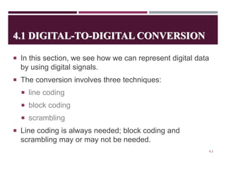
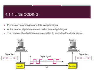
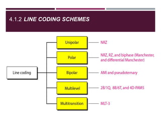
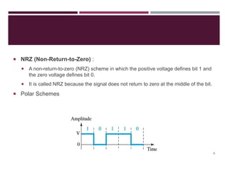
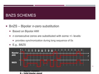
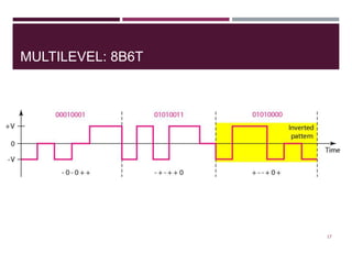
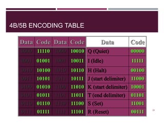
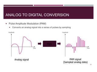
DIGITAL TRANSMISSION
CHAPTER- 04
- MEENAKSHI PAUL
OUTLINE
4.1 DIGITAL-TO-DIGITAL CONVERSION
4.1.1 Line Coding
4.1.2 Line Coding Schemes
4.1.3 Block Coding
4.1.4 Scrambling
4.2 ANALOG-TO-DIGITAL CONVERSION
4.2.1 Pulse Code Modulation (PCM)
4.2.2 Delta Modulation (DM)
4.3 TRANSMISSION MODES
4.3.1 Parallel Transmission
4.3.2 Serial Transmission
2
4.1 DIGITAL-TO-DIGITAL CONVERSION
 In this section, we see how we can represent digital data
by using digital signals.
 The conversion involves three techniques:
 line coding
 block coding
 scrambling
 Line coding is always needed; block coding and
scrambling may or may not be needed.
4.3
4.1.1 LINE CODING
 Process of converting binary data to digital signal
 At the sender, digital data are encoded into a digital signal.
 The receiver, the digital data are recreated by decoding the digital signal.
4
4.1.2 LINE CODING SCHEMES
4.5
 NRZ (Non-Return-to-Zero) :
 A non-return-to-zero (NRZ) scheme in which the positive voltage defines bit 1 and
the zero voltage defines bit 0.
 It is called NRZ because the signal does not return to zero at the middle of the bit.
 Polar Schemes
6
LINE CODING METHODS
 Unipolar
 Uses only one voltage level (one side of time axis)
 Polar
 Uses two voltage levels (negative and positive)
 E.g., NRZ, RZ, Manchester, Differential Manchester
 Bipolar
 Uses three voltage levels (+, 0, and –) for data bits
 Multilevel
7
UNIPOLAR
 Simplest form of digital encoding
Rarely used
 Only one polarity of voltage is used
 E.g., polarity assigned to 1
8
t
0 1 0 0 1 1 0 0
POLAR ENCODING
 Two voltage levels (+,-) represent data bits
 Most popular four
 Nonreturn-to-Zero (NRZ)
 Return-to-Zero (RZ)
 Manchester
 Differential Manchester
9
NRZ ENCODING
 Nonreturn to Zero
 NRZ-L (NRZ-Level): Signal level depends on bit value
 NRZ-I (NRZ-Invert): Signal is inverted if 1 is encountered
10
t
0 1 0 0 1 1 1 0
t
0 1 0 0 1 1 1 0
N = Bit rate
Save = Average signal rate
RZ ENCODING
 Return to Zero
 Uses three voltage levels: +, - and 0, but only + and - represent data bits
 Half way thru each bit, signal returns to zero
11
t
0 1 0 0 1 1 0 0 ?
MANCHESTER ENCODING
 Uses an inversion at the middle of each bit
 For bit representation
 For synchronization
12
t
0 1 0 0 1 1 0 1 = 0
= 1
DIFFERENTIAL MANCHESTER
ENCODING
 The inversion on the middle of each bit is only for synchronization
 Transition at the beginning of each bit tells the value
13
t
0 1 0 0 1 1 0 1
BIPOLAR ENCODING
 Bipolar encoding uses three voltage levels: +, -
and 0
 Each of all three levels represents a bit
 E.g., Bipolar AMI (Alternate Mark Inversion)
 0V always represents binary 0
 Binary 1s are represented by alternating + and -
14t
0 1 0 0 1 1 0 1
BNZS SCHEMES
 BnZS – Bipolar n-zero substitution
 Based on Bipolar AMI
 n consecutive zeros are substituted with some +/- levels
 provides synchronization during long sequence of 0s
 E.g., B8ZS
15
t
1 1 0 0 0 0 0 0 0 0 1 1 0 0 0 0 0 1 0
Bipolar
AMI
B8ZS
V B 0 V000 B
V – Bipolar violation
B – Valid bipolar signal
OTHER SCHEMES
 mBnL
 m data elements are substituted with n signal elements
 E.g., 2B1Q (two binary, 1 quaternary)
16
t
00 11 01 10 01 10 11 00
-3
-1
+1
+3 Bit sequence Voltage level
00 -3
01 -1
10 +3
11 +1
MULTILEVEL: 8B6T
 Eight binary, six ternary
17
BLOCK CODING
 Improves the performance of line coding
 Provides
 Synchronization
 Error detection
18
Division Substitution
Line
Coding
:
0010
1101
0001
:
…01011010001… :
10110
01011
01010
:
t
4B/5B ENCODING TABLE
19
Data Code Data Code
0000 11110 1000 10010
0001 01001 1001 10011
0010 10100 1010 10110
0011 10101 1011 10111
0100 01010 1100 11010
0101 01011 1101 11011
0110 01110 1110 11100
0111 01111 1111 11101
Data Code
Q (Quiet) 00000
I (Idle) 11111
H (Halt) 00100
J (start delimiter) 11000
K (start delimiter) 10001
T (end delimiter) 01101
S (Set) 11001
R (Reset) 00111
ANALOG TO DIGITAL CONVERSION
 Pulse Amplitude Modulation (PAM)
 Converts an analog signal into a series of pulses by sampling
20
PAM
Analog signal PAM signal
(Sampled analog data)
4.2.1PULSE CODE MODULATION (PCM)
 Converts an analog signal into a digital signal
 PAM
 Quantization
 Binary encoding
 Line coding
21
PCM: QUANTIZATION
 Converts continuous values of data to a finite number of
discrete values
22
1 2 3 4 5 6 70
Input
2
4
6
Output
PCM: QUANTIZATION
23
Quantization
QUANTIZATION ERROR
 Assume sine-wave input and uniform quantization
 Known as the 6 dB/bit approximation
24
See also: http://en.wikipedia.org/wiki/Quantization_error#Quantization_noise_model
EXAMPLE: QUANTIZATION ERROR
 A telephone subscriber line must have an SNRdB above 40. What is the
minimum number of bits per sample?
25
Solution
We can calculate the number of bits as
Telephone companies usually assign 7 or 8 bits per sample.
PCM: BINARY ENCODING
 Maps discrete values to binary digits
26
PCM: THE WHOLE PROCESS
27
MINIMUM SAMPLING RATE
 Nyquist Theorem:
28
Sampling rate must be greater than
twice the highest frequency
t
sampling interval
Ex. Find the maximum sampling
interval for recording human voice
(freq. range 300Hz – 3000Hz)
SAMPLING AND BIT RATE
 Ex. Calculate the minimum bit rate for recording
human voice, if each sample requires 60 levels
of precision
29
TRANSMISSION MODES
 The transmission of binary data across a link can be
accomplished in either parallel or serial mode.
 In parallel mode, multiple bits are sent with each clock
tick.
 In serial mode, 1 bit is sent with each clock tick.
 While there is only one way to send parallel data, there
are three subclasses of serial transmission:
asynchronous, synchronous, and isochronous.
 Topics discussed in this section:
 Parallel Transmission
 Serial Transmission
4.30
DATA TRANSMISSION AND MODES
4.31
4.32
Figure 4.32 Parallel transmission
4.33
Figure 4.33 Serial transmission
4.34
In asynchronous transmission, we send 1 start bit (0) at the beginning and 1
or more stop bits (1s) at the end of each byte. There may be a gap between
each byte.
Note
4.35
Asynchronous here means “asynchronous at the byte level,”
but the bits are still synchronized;
their durations are the same.
Note
4.36
Figure 4.34 Asynchronous transmission
4.37
In synchronous transmission, we send bits one after another without start or
stop bits or gaps. It is the responsibility of the receiver to group the bits.
Note
4.38
Figure 4.35 Synchronous transmission

04 digital transmission

  • 1.
  • 2.
    OUTLINE 4.1 DIGITAL-TO-DIGITAL CONVERSION 4.1.1Line Coding 4.1.2 Line Coding Schemes 4.1.3 Block Coding 4.1.4 Scrambling 4.2 ANALOG-TO-DIGITAL CONVERSION 4.2.1 Pulse Code Modulation (PCM) 4.2.2 Delta Modulation (DM) 4.3 TRANSMISSION MODES 4.3.1 Parallel Transmission 4.3.2 Serial Transmission 2
  • 3.
    4.1 DIGITAL-TO-DIGITAL CONVERSION In this section, we see how we can represent digital data by using digital signals.  The conversion involves three techniques:  line coding  block coding  scrambling  Line coding is always needed; block coding and scrambling may or may not be needed. 4.3
  • 4.
    4.1.1 LINE CODING Process of converting binary data to digital signal  At the sender, digital data are encoded into a digital signal.  The receiver, the digital data are recreated by decoding the digital signal. 4
  • 5.
    4.1.2 LINE CODINGSCHEMES 4.5
  • 6.
     NRZ (Non-Return-to-Zero):  A non-return-to-zero (NRZ) scheme in which the positive voltage defines bit 1 and the zero voltage defines bit 0.  It is called NRZ because the signal does not return to zero at the middle of the bit.  Polar Schemes 6
  • 7.
    LINE CODING METHODS Unipolar  Uses only one voltage level (one side of time axis)  Polar  Uses two voltage levels (negative and positive)  E.g., NRZ, RZ, Manchester, Differential Manchester  Bipolar  Uses three voltage levels (+, 0, and –) for data bits  Multilevel 7
  • 8.
    UNIPOLAR  Simplest formof digital encoding Rarely used  Only one polarity of voltage is used  E.g., polarity assigned to 1 8 t 0 1 0 0 1 1 0 0
  • 9.
    POLAR ENCODING  Twovoltage levels (+,-) represent data bits  Most popular four  Nonreturn-to-Zero (NRZ)  Return-to-Zero (RZ)  Manchester  Differential Manchester 9
  • 10.
    NRZ ENCODING  Nonreturnto Zero  NRZ-L (NRZ-Level): Signal level depends on bit value  NRZ-I (NRZ-Invert): Signal is inverted if 1 is encountered 10 t 0 1 0 0 1 1 1 0 t 0 1 0 0 1 1 1 0 N = Bit rate Save = Average signal rate
  • 11.
    RZ ENCODING  Returnto Zero  Uses three voltage levels: +, - and 0, but only + and - represent data bits  Half way thru each bit, signal returns to zero 11 t 0 1 0 0 1 1 0 0 ?
  • 12.
    MANCHESTER ENCODING  Usesan inversion at the middle of each bit  For bit representation  For synchronization 12 t 0 1 0 0 1 1 0 1 = 0 = 1
  • 13.
    DIFFERENTIAL MANCHESTER ENCODING  Theinversion on the middle of each bit is only for synchronization  Transition at the beginning of each bit tells the value 13 t 0 1 0 0 1 1 0 1
  • 14.
    BIPOLAR ENCODING  Bipolarencoding uses three voltage levels: +, - and 0  Each of all three levels represents a bit  E.g., Bipolar AMI (Alternate Mark Inversion)  0V always represents binary 0  Binary 1s are represented by alternating + and - 14t 0 1 0 0 1 1 0 1
  • 15.
    BNZS SCHEMES  BnZS– Bipolar n-zero substitution  Based on Bipolar AMI  n consecutive zeros are substituted with some +/- levels  provides synchronization during long sequence of 0s  E.g., B8ZS 15 t 1 1 0 0 0 0 0 0 0 0 1 1 0 0 0 0 0 1 0 Bipolar AMI B8ZS V B 0 V000 B V – Bipolar violation B – Valid bipolar signal
  • 16.
    OTHER SCHEMES  mBnL m data elements are substituted with n signal elements  E.g., 2B1Q (two binary, 1 quaternary) 16 t 00 11 01 10 01 10 11 00 -3 -1 +1 +3 Bit sequence Voltage level 00 -3 01 -1 10 +3 11 +1
  • 17.
    MULTILEVEL: 8B6T  Eightbinary, six ternary 17
  • 18.
    BLOCK CODING  Improvesthe performance of line coding  Provides  Synchronization  Error detection 18 Division Substitution Line Coding : 0010 1101 0001 : …01011010001… : 10110 01011 01010 : t
  • 19.
    4B/5B ENCODING TABLE 19 DataCode Data Code 0000 11110 1000 10010 0001 01001 1001 10011 0010 10100 1010 10110 0011 10101 1011 10111 0100 01010 1100 11010 0101 01011 1101 11011 0110 01110 1110 11100 0111 01111 1111 11101 Data Code Q (Quiet) 00000 I (Idle) 11111 H (Halt) 00100 J (start delimiter) 11000 K (start delimiter) 10001 T (end delimiter) 01101 S (Set) 11001 R (Reset) 00111
  • 20.
    ANALOG TO DIGITALCONVERSION  Pulse Amplitude Modulation (PAM)  Converts an analog signal into a series of pulses by sampling 20 PAM Analog signal PAM signal (Sampled analog data)
  • 21.
    4.2.1PULSE CODE MODULATION(PCM)  Converts an analog signal into a digital signal  PAM  Quantization  Binary encoding  Line coding 21
  • 22.
    PCM: QUANTIZATION  Convertscontinuous values of data to a finite number of discrete values 22 1 2 3 4 5 6 70 Input 2 4 6 Output
  • 23.
  • 24.
    QUANTIZATION ERROR  Assumesine-wave input and uniform quantization  Known as the 6 dB/bit approximation 24 See also: http://en.wikipedia.org/wiki/Quantization_error#Quantization_noise_model
  • 25.
    EXAMPLE: QUANTIZATION ERROR A telephone subscriber line must have an SNRdB above 40. What is the minimum number of bits per sample? 25 Solution We can calculate the number of bits as Telephone companies usually assign 7 or 8 bits per sample.
  • 26.
    PCM: BINARY ENCODING Maps discrete values to binary digits 26
  • 27.
    PCM: THE WHOLEPROCESS 27
  • 28.
    MINIMUM SAMPLING RATE Nyquist Theorem: 28 Sampling rate must be greater than twice the highest frequency t sampling interval Ex. Find the maximum sampling interval for recording human voice (freq. range 300Hz – 3000Hz)
  • 29.
    SAMPLING AND BITRATE  Ex. Calculate the minimum bit rate for recording human voice, if each sample requires 60 levels of precision 29
  • 30.
    TRANSMISSION MODES  Thetransmission of binary data across a link can be accomplished in either parallel or serial mode.  In parallel mode, multiple bits are sent with each clock tick.  In serial mode, 1 bit is sent with each clock tick.  While there is only one way to send parallel data, there are three subclasses of serial transmission: asynchronous, synchronous, and isochronous.  Topics discussed in this section:  Parallel Transmission  Serial Transmission 4.30
  • 31.
  • 32.
  • 33.
  • 34.
    4.34 In asynchronous transmission,we send 1 start bit (0) at the beginning and 1 or more stop bits (1s) at the end of each byte. There may be a gap between each byte. Note
  • 35.
    4.35 Asynchronous here means“asynchronous at the byte level,” but the bits are still synchronized; their durations are the same. Note
  • 36.
  • 37.
    4.37 In synchronous transmission,we send bits one after another without start or stop bits or gaps. It is the responsibility of the receiver to group the bits. Note
  • 38.