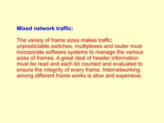
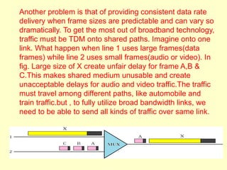
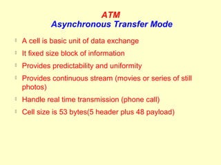
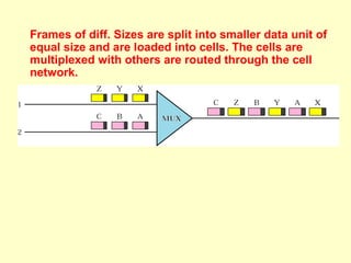
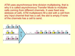
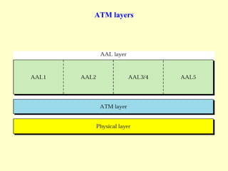
ATM
Asynchronous Transfer Mode
ATM
    Asynchronous Transfer Mode

Cell relay protocols



Designed by ATM forum (formed in Oct. 1991 )and


adopted by ITU-T
Combination of ATM and SONET allows high                 speed
interconnection of the world network.
Also thought as “High way”



Signaling (connection setup) Protocol: Q.2931–


Discovering routes and allocating resources at switches
Design Goals
   Optimize use of high data rate transmission media e.g
    fiber optics and new equipments are less susceptible to
    noise degradation. A technology is needed to take
    advantage of both factors.
   The system must interface with existing systems and
    provide wide area interconnectivity B/W them without
    lowering their effectiveness.
   The design must be implemented inexpensively so that
    cost would not be a barrier to adopt.
   The new system must be able to work with existing
    telecom hierarchies(local loop, local provider, long haul
    and so on).
Design Goals

   The new system should be connection oriented to
    ensure accurate and predictable delivery.
   One objective is to move as many of functions to
    hardware as possible (for speed) and eliminate as many
    software functions as possible (again for speed).
Problems

Problems associated with existing systems;
Frame networks:
Before ATM,DC at DDL based on frame switching and
frame networks. Different protocols use frames of varying
size. As network become more complex, the information
that must be carried in header become more expensive.
The result larger and larger headers relative to the size of
data unit. In response, some protocols have enlarged the
size of the data unit to make header use more efficient.
Unfortunately, large data fields create waste if there is not
much information to transmit. To improve utilization, some
protocols provide variable frame size to users.
Mixed network traffic:

The variety of frame sizes makes traffic
unpredictable.switches, multiplexes and router must
incorporate software systems to manage the various
sizes of frames. A great deal of header information
must be read and each bit counted and evaluated to
ensure the integrity of every frame. Internetworking
among different frame works is slow and expensive.
Another problem is that of providing consistent data rate
delivery when frame sizes are predictable and can vary so
dramatically. To get the most out of broadband technology,
traffic must be TDM onto shared paths. Imagine onto one
link. What happen when line 1 uses large frames(data
frames) while line 2 uses small frames(audio or video). In
fig. Large size of X create unfair delay for frame A,B &
C.This makes shared medium unusable and create
unacceptable delays for audio and video traffic.The traffic
must travel among different paths, like automobile and
train traffic.but , to fully utilize broad bandwidth links, we
need to be able to send all kinds of traffic over same link.
ATM
             Asynchronous Transfer Mode
   A cell is basic unit of data exchange
   It fixed size block of information
   Provides predictability and uniformity
   Provides continuous stream (movies or series of still
    photos)
   Handle real time transmission (phone call)
   Cell size is 53 bytes(5 header plus 48 payload)
Frames of diff. Sizes are split into smaller data unit of
equal size and are loaded into cells. The cells are
multiplexed with others are routed through the cell
network.
ATM uses asynchronous time division multiplexing, that is
why it is called asynchronous Transfer Mode to multiplex
cells coming from different channels. It uses fixed size
slot(size of cell). ATM multiplexers fill a slot with a cell from
any input channel that has a cell; the slot is empty if none
of the channels has a cell to send.
Architecture of an ATM network


UNI- user to network interface
NNI- network to network interface
TP, VPs, and VCs


TP- transmission path
VPs- virtual paths
VCs- virtual paths
Example of VPs and VCs
a virtual connection is defined by a pair
of numbers: the VPI and the VCI.
Connection identifier:
Virtual connection identifiers in UNIs and NNIs
An ATM cell
Routing with a switch
ATM layers
Physical layer
ATM cells can be carried by any physical layer carrier like


Ethernet& wireless LAN.
   SONET is original design on which ATM based
   Reason for using SONET
                High data rate & boundaries of cell can be clearly
defined by pointer

Other physical technologies can also be used
                 The receiver is used to guess the end of cell and
apply CRC to 5 byte of header, if there is no error then count 52
bytes back to find begging of cell.
Transmission Convergence (TC) handles error detection,
framing & Physical medium dependent (PMD) sublayer
handles encoding
ATM layers in end points & switches
ATM layer
   It provides routing, traffic management, switching &
    multiplexing services. Also Handles virtual circuits, cell
    header generation, flow control
   It process outgoing traffic by accepting 48 bytes
    segment from AAL sub layer & transform them into 53
    byte cell by addition of a 5 bytes header.
ATM headers
GFC(4 bit provides flow control at UNI,no need in NNI),VPI(8 bit in UNI& 12
bit in NNI), VCI(16 bit in both frame headers),PT(3 bit, define user data/
managerial info.)CLP(1 bit),HEC(1 byte)
Application Adaptation layer AAL
   AAL was designed to accept any types of payload, both
    data frames and streams of bits.
   It has two sub layers:
    CS(convergence sub layer)& SAR(segmentation & Reassembly)
   These two layers break the data into chunks that are
    encapsulated into a cell at ATM layer.
   CS checks the integrity of data and SAR segmented the
    data at source & reassembly the data at the designation
   There many version of AAL:AAL1,AAL2,AAL3/4,AAL5
AAL1
   Support Apps. That transfer info. At constant bit rate
    such as video and voice
   It allows ATM to connect existing digital telephone
    network such as voice channels and T lines.
   In this CS divides bit stream into 47 bytes segments and
    pass them to SAR. CS adds no header here but SAR
    adds 1 byte header and passes the 48 bytes segment to
    ATM layer.
   SN(sequence number)- 4 bit used to order the bits
   SNP(sequence number protection)-4bit protect the first
    field
AAL1
AAL2
   Original design was to support a variable data rate bit
    stream
   But it has been redesigned for low bit rate traffic and
    short frame such as audio, video or fax.
   It is also uses in mobile telephony.
   The process of encapsulating short frames from the
    same source(the same user of mobile phone) or from
    several sources(several users of mobile telephones)
    into one cell is shown.
AAL2
AAL3/4
   AAL3 support connection oriented data services
   AAL4 support connection less data services
   The fundamental issues of the two were same therefore
    they have been combined into single format AAL3/4.
   It provides compressive sequencing and error control
    mechanism.
   The encapsulation process is shown.
AAL3/4
AAL5
   AAL 5 designed as replacement for AAL3/4
   No PDU information in ATM header
   Only uses 1 bit of ATM header to mark end of PDU
   Does not require additional per-cell headers/trailers
   CS-PDU contains data with only 8-byte trailer
   Uses stronger error correction at PDU level (CRC- 32)
   Protection against lost, corrupt and misordered cells is provided by
    CS-PDU
AAL5
Applications

• Government
• Long distance provider
• Bell telephone company
• ISP
• Large banks
• Frame relay
• Large universities
ATM support many interfaces

   FDDI100 Mbps
   SONETOC-3—155 Mbps, OC-12—622 Mbps
   DS-11.544 MBPS
   DS-344.736 Mbps
   E12.048 Mbps
   E334.368 Mbps
   UTP &STP25.6 Mbps
QoS in ATM


   CBR: Designed for real-time audio or video services
   VBR: Variable-bit-rate
     – VBR-RT [Real-time]
         » For real time services
         » Uses compression techniques to create a variable bit rate.
     – VBR-NRT [Non-real-time]
         » Uses compression but for non real time.
   ABR: Available bit rate
     – Delivers cells at a minimum rate.
     – If more network capacity is available, this minimum rate can be exceeded.
     – Suitable for applications that are bursty.
   UBR: Unspecified bit rate; Best effort delivery that does not guarantee
    anything.
Figure 23.28   Relationship of service classes to the total capacity


   User-Related attributes: Defines how fast the user
    want to send data.
     – Sustained cell rate: Average cell rate over a long time interval.
       Actual cell rate can be higher or lower but average should be
       equal or less than SCR
     – Peak cell rate: Sender’s maximum cell rate.
     – Minimum cell rate: Sender’s minimum cell rate.
     – Cell Variation delay tolerance: Measure of variation in cell
       transmission times. This is the difference between the
       minimum and maximum delays in delivering the cells.
ATM Network


   Network related attributes are those that define
    characteristics of the network.
     – Cell loss ratio (CLR): Fraction of cells lost (or delivered so
       late that they are considered lost) during transmission.
     – Cell transfer delay (CTD): average time needed for a cell to
       travel from source to destination.
     – Cell delay variation (CDV): difference between CTD
       maximum and CTD minimum
     – Cell error ratio (CER): Fraction of the cells delivered in
       error.
Quality of Service: Flow Demands
   Reliability: Lack of reliability means losing a packet or
    acknowledgement, which entails retransmission. Different application
    programs need different levels of reliability.
   Delay: Source-to-destination delay. Delay tolerance varies between
    applications.
   Jitter: Variation in delay for packets belonging to the same flow. Real-
    time audio and video applications cannot tolerate high jitter.
   Bandwidth: bits per second
   Flow classes: Depend on flow characteristics, we can classify flow into
    groups e.g., CBR, UBR, etc.

Atm( Asynchronous Transfer mode )

  • 1.
  • 2.
    ATM Asynchronous Transfer Mode Cell relay protocols  Designed by ATM forum (formed in Oct. 1991 )and  adopted by ITU-T Combination of ATM and SONET allows high speed interconnection of the world network. Also thought as “High way”  Signaling (connection setup) Protocol: Q.2931–  Discovering routes and allocating resources at switches
  • 3.
    Design Goals  Optimize use of high data rate transmission media e.g fiber optics and new equipments are less susceptible to noise degradation. A technology is needed to take advantage of both factors.  The system must interface with existing systems and provide wide area interconnectivity B/W them without lowering their effectiveness.  The design must be implemented inexpensively so that cost would not be a barrier to adopt.  The new system must be able to work with existing telecom hierarchies(local loop, local provider, long haul and so on).
  • 4.
    Design Goals  The new system should be connection oriented to ensure accurate and predictable delivery.  One objective is to move as many of functions to hardware as possible (for speed) and eliminate as many software functions as possible (again for speed).
  • 5.
    Problems Problems associated withexisting systems; Frame networks: Before ATM,DC at DDL based on frame switching and frame networks. Different protocols use frames of varying size. As network become more complex, the information that must be carried in header become more expensive. The result larger and larger headers relative to the size of data unit. In response, some protocols have enlarged the size of the data unit to make header use more efficient. Unfortunately, large data fields create waste if there is not much information to transmit. To improve utilization, some protocols provide variable frame size to users.
  • 6.
    Mixed network traffic: Thevariety of frame sizes makes traffic unpredictable.switches, multiplexes and router must incorporate software systems to manage the various sizes of frames. A great deal of header information must be read and each bit counted and evaluated to ensure the integrity of every frame. Internetworking among different frame works is slow and expensive.
  • 7.
    Another problem isthat of providing consistent data rate delivery when frame sizes are predictable and can vary so dramatically. To get the most out of broadband technology, traffic must be TDM onto shared paths. Imagine onto one link. What happen when line 1 uses large frames(data frames) while line 2 uses small frames(audio or video). In fig. Large size of X create unfair delay for frame A,B & C.This makes shared medium unusable and create unacceptable delays for audio and video traffic.The traffic must travel among different paths, like automobile and train traffic.but , to fully utilize broad bandwidth links, we need to be able to send all kinds of traffic over same link.
  • 8.
    ATM Asynchronous Transfer Mode  A cell is basic unit of data exchange  It fixed size block of information  Provides predictability and uniformity  Provides continuous stream (movies or series of still photos)  Handle real time transmission (phone call)  Cell size is 53 bytes(5 header plus 48 payload)
  • 9.
    Frames of diff.Sizes are split into smaller data unit of equal size and are loaded into cells. The cells are multiplexed with others are routed through the cell network.
  • 10.
    ATM uses asynchronoustime division multiplexing, that is why it is called asynchronous Transfer Mode to multiplex cells coming from different channels. It uses fixed size slot(size of cell). ATM multiplexers fill a slot with a cell from any input channel that has a cell; the slot is empty if none of the channels has a cell to send.
  • 11.
    Architecture of anATM network UNI- user to network interface NNI- network to network interface
  • 12.
    TP, VPs, andVCs TP- transmission path VPs- virtual paths VCs- virtual paths
  • 13.
  • 14.
    a virtual connectionis defined by a pair of numbers: the VPI and the VCI. Connection identifier:
  • 15.
  • 16.
  • 17.
  • 18.
  • 19.
    Physical layer ATM cellscan be carried by any physical layer carrier like  Ethernet& wireless LAN.  SONET is original design on which ATM based  Reason for using SONET High data rate & boundaries of cell can be clearly defined by pointer Other physical technologies can also be used The receiver is used to guess the end of cell and apply CRC to 5 byte of header, if there is no error then count 52 bytes back to find begging of cell. Transmission Convergence (TC) handles error detection, framing & Physical medium dependent (PMD) sublayer handles encoding
  • 20.
    ATM layers inend points & switches
  • 21.
    ATM layer  It provides routing, traffic management, switching & multiplexing services. Also Handles virtual circuits, cell header generation, flow control  It process outgoing traffic by accepting 48 bytes segment from AAL sub layer & transform them into 53 byte cell by addition of a 5 bytes header.
  • 22.
    ATM headers GFC(4 bitprovides flow control at UNI,no need in NNI),VPI(8 bit in UNI& 12 bit in NNI), VCI(16 bit in both frame headers),PT(3 bit, define user data/ managerial info.)CLP(1 bit),HEC(1 byte)
  • 23.
    Application Adaptation layerAAL  AAL was designed to accept any types of payload, both data frames and streams of bits.  It has two sub layers: CS(convergence sub layer)& SAR(segmentation & Reassembly)  These two layers break the data into chunks that are encapsulated into a cell at ATM layer.  CS checks the integrity of data and SAR segmented the data at source & reassembly the data at the designation  There many version of AAL:AAL1,AAL2,AAL3/4,AAL5
  • 24.
    AAL1  Support Apps. That transfer info. At constant bit rate such as video and voice  It allows ATM to connect existing digital telephone network such as voice channels and T lines.  In this CS divides bit stream into 47 bytes segments and pass them to SAR. CS adds no header here but SAR adds 1 byte header and passes the 48 bytes segment to ATM layer.  SN(sequence number)- 4 bit used to order the bits  SNP(sequence number protection)-4bit protect the first field
  • 25.
  • 26.
    AAL2  Original design was to support a variable data rate bit stream  But it has been redesigned for low bit rate traffic and short frame such as audio, video or fax.  It is also uses in mobile telephony.  The process of encapsulating short frames from the same source(the same user of mobile phone) or from several sources(several users of mobile telephones) into one cell is shown.
  • 27.
  • 28.
    AAL3/4  AAL3 support connection oriented data services  AAL4 support connection less data services  The fundamental issues of the two were same therefore they have been combined into single format AAL3/4.  It provides compressive sequencing and error control mechanism.  The encapsulation process is shown.
  • 29.
  • 30.
    AAL5  AAL 5 designed as replacement for AAL3/4  No PDU information in ATM header  Only uses 1 bit of ATM header to mark end of PDU  Does not require additional per-cell headers/trailers  CS-PDU contains data with only 8-byte trailer  Uses stronger error correction at PDU level (CRC- 32)  Protection against lost, corrupt and misordered cells is provided by CS-PDU
  • 31.
  • 32.
    Applications • Government • Longdistance provider • Bell telephone company • ISP • Large banks • Frame relay • Large universities
  • 33.
    ATM support manyinterfaces  FDDI100 Mbps  SONETOC-3—155 Mbps, OC-12—622 Mbps  DS-11.544 MBPS  DS-344.736 Mbps  E12.048 Mbps  E334.368 Mbps  UTP &STP25.6 Mbps
  • 34.
    QoS in ATM  CBR: Designed for real-time audio or video services  VBR: Variable-bit-rate – VBR-RT [Real-time] » For real time services » Uses compression techniques to create a variable bit rate. – VBR-NRT [Non-real-time] » Uses compression but for non real time.  ABR: Available bit rate – Delivers cells at a minimum rate. – If more network capacity is available, this minimum rate can be exceeded. – Suitable for applications that are bursty.  UBR: Unspecified bit rate; Best effort delivery that does not guarantee anything.
  • 35.
    Figure 23.28 Relationship of service classes to the total capacity  User-Related attributes: Defines how fast the user want to send data. – Sustained cell rate: Average cell rate over a long time interval. Actual cell rate can be higher or lower but average should be equal or less than SCR – Peak cell rate: Sender’s maximum cell rate. – Minimum cell rate: Sender’s minimum cell rate. – Cell Variation delay tolerance: Measure of variation in cell transmission times. This is the difference between the minimum and maximum delays in delivering the cells.
  • 36.
    ATM Network  Network related attributes are those that define characteristics of the network. – Cell loss ratio (CLR): Fraction of cells lost (or delivered so late that they are considered lost) during transmission. – Cell transfer delay (CTD): average time needed for a cell to travel from source to destination. – Cell delay variation (CDV): difference between CTD maximum and CTD minimum – Cell error ratio (CER): Fraction of the cells delivered in error.
  • 37.
    Quality of Service:Flow Demands  Reliability: Lack of reliability means losing a packet or acknowledgement, which entails retransmission. Different application programs need different levels of reliability.  Delay: Source-to-destination delay. Delay tolerance varies between applications.  Jitter: Variation in delay for packets belonging to the same flow. Real- time audio and video applications cannot tolerate high jitter.  Bandwidth: bits per second  Flow classes: Depend on flow characteristics, we can classify flow into groups e.g., CBR, UBR, etc.