Answer three basicQuestions :
2
What? – what is ATM
How ? – how it works.
Why? -- why it’s used (benefits)
Presentation Objectives
3.
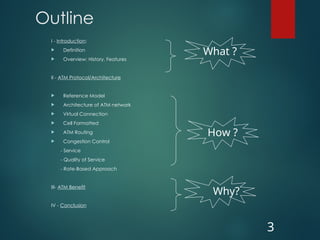
Outline
I - Introduction:
Definition
Overview: History, Features
II - ATM Protocol/Architecture
Reference Model
Architecture of ATM network
Virtual Connection
Cell Formatted
ATM Routing
Congestion Control
- Service
- Quality of Service
- Rate-Based Approach
III- ATM Benefit
IV - Conclusion
3
What ?
How ?
Why?
4.
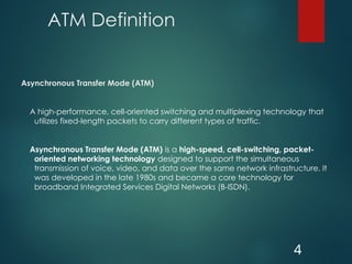
ATM Definition
Asynchronous TransferMode (ATM)
A high-performance, cell-oriented switching and multiplexing technology that
utilizes fixed-length packets to carry different types of traffic.
Asynchronous Transfer Mode (ATM) is a high-speed, cell-switching, packet-
oriented networking technology designed to support the simultaneous
transmission of voice, video, and data over the same network infrastructure. It
was developed in the late 1980s and became a core technology for
broadband Integrated Services Digital Networks (B-ISDN).
4
5.
ATM Overview
ATM:
ATMwas designed in early 1990s
ATM aim is to expedite the process of integrating AMT into the
market.
It is designed for high-performance multimedia networking.
It enables carriers to transmit voice, video, and future media
applications.
It’s suitable for bursty traffic.
It allows communication between devices that operate at different
speeds.
It can be offered as an end-user service by service providers, or as
a networking infrastructure
It is a set of international interface and signaling standards defined
by ITU-T Standards Sector.
5
6.
ATM Overview
So far,ATM has been implemented in :
PC, workstation, and server network interface cards
Switched-Ethernet and token-ring workgroup hubs
ATM enterprise network switches
ATM multiplexers
ATM-edge switches
ATM-backbone switches
6
7.
ATM Features
Main featuresof ATM
Service is connection oriented, with data transferred over a VC
A cell-switched network (architecture).
Fixed-size cell (53-Bytes)
Uses Asynchronous time-division multiplexing (Asynchronous TDM)
The Quantity of Service (QofS) enable carriers to transmit voice,
data, and video.
ATM is independent of the transmission medium. ATM cells can be
sent on a wire or fiber, and can also be packaged inside the
payload of other carrier system.
7
8.
Fixed and SmallSize Cell
Advantage:
Transmitted with predictability and uniformity.
Easy to be multiplexed with other cells, and routed through the cell network.
With high speed of the links, small and fixed-size cells seem to arrive their
respective destinations in an approximation of continuous stream, despite
interleaving. E.g. phone call.
Simpler buffer hardware, avoiding memory fragmentation problem
Simpler cells scheduling:
- Easier to allocate different bandwidths and delays to different VCs.
- Easier to implement priority
- Fixed sized can be switched in parallel in synchronous fashion.
It’s suitable for time-critical information such as voice or video
Quicker recovery in case of circuit failure.
8
9.
Fixed-Size and SmallCell
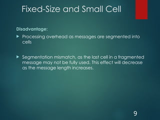
Disadvantage:
Processing overhead as messages are segmented into
cells
Segmentation mismatch, as the last cell in a fragmented
message may not be fully used. This effect will decrease
as the message length increases.
9
10.
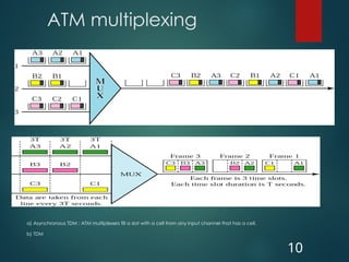
ATM multiplexing
a) AsynchronousTDM : ATM multiplexers fill a slot with a cell from any input channel that has a cell.
b) TDM
10
ATM Technology
Reference Model
12
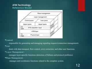
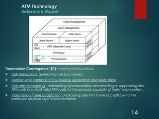
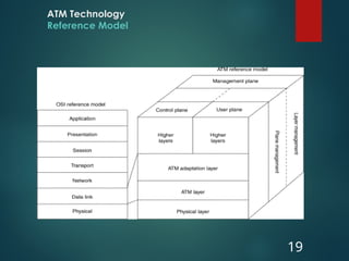
Control
responsiblefor generating and managing signaling request (connection management).
User
deals with data transport, flow control, error correction, and other user functions.
Layer Management :
manages layer-specific functions (detection of failures and protocol problems)
Plane Management:
manages and coordinates functions related to the complete system.
13.
ATM Technology
Reference Model
13
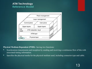
PhysicalMedium-Dependent (PMD)– having two functions:
Synchronizes transmission and reception by sending and receiving a continuous flow of bits with
associated timing information.
Specifies the physical media for the physical medium used, including connector type and cable.
14.
ATM Technology
Reference Model
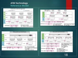
TransmissionConvergence (TC) – having four functions:
Cell delineation, generating cell boundaries.
Header error control (HEC) sequence generation and verification
Cell-rate decoupling, maintaining synchronization and inserting or suppressing idle
ATM cells to rate of valid ATM cells to the payload capacity of transmission system.
Transmission frame adaptation, packaging cells into frame acceptable to the
particular physical layer implementation.
14
ATM Technology
Reference Model
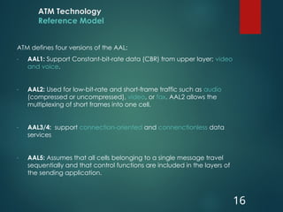
ATMdefines four versions of the AAL:
- AAL1: Support Constant-bit-rate data (CBR) from upper layer; video
and voice.
- AAL2: Used for low-bit-rate and short-frame traffic such as audio
(compressed or uncompressed), video, or fax. AAL2 allows the
multiplexing of short frames into one cell.
- AAL3/4: support connection-oriented and connenctionless data
services
- AAL5: Assumes that all cells belonging to a single message travel
sequentially and that control functions are included in the layers of
the sending application.
16
17.
ATM Technology
Reference Model
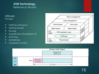
ATMAdaptation Layer (AAL)
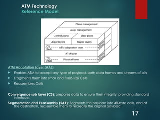
Enables ATM to accept any type of payload, both data frames and streams of bits
Fragments them into small and fixed-size Cells
Reassembles Cells
Convergence sub layer (CS): prepares data to ensure their integrity, providing standard
interface.
Segmentation and Reassembly (SAR): Segments the payload into 48-byte cells, and at
the destination, reassemble them to recreate the original payload.
17
ATM Technology
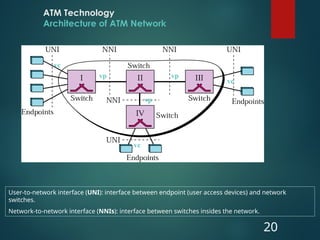
Architecture ofATM Network
20
User-to-network interface (UNI): interface between endpoint (user access devices) and network
switches.
Network-to-network interface (NNIs): interface between switches insides the network.
vc
vc
vc
vp vp
vp
21.
ATM Technology
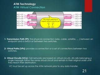
ATM VirtualConnection
1- Transmission Path (TP): the physical connection (wire, cable, satellite, … ) between an
endpoint and a switch or between two switches.
2- Virtual Paths (VPs): provides a connection or a set of connections between two
switches.
3- Virtual Circuits (VCs): Cell networks are based on virtual circuits. All cells belonging a
single message follow the same virtual circuit and remain in their original order until
they reach their destination.
VC must be set up across the ATM network prior to any data transfer.
21
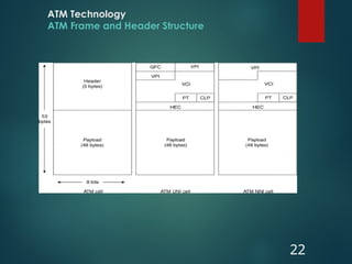
ATM Technology
ATM Frameand Header Structure
23
Generic Flow Control (GFC)
provides flow control at the UNI level
Virtual Path Identifier (VPI)
identifies the cell’s next VP to pass through a series of network.
Virtual Channel Identifier (VCI)
Identifies the cell’s next VC inside the VP.
Payload Type (PT)
The first bit indicates whether the cell contains user data (bit 0) or control data (bit 1).
The second bit indicates congestion (0 = no congestion, 1 = congestion), and
The third bit indicates whether the cell is the last in a series of cells (1 = last cells for the frame)
Cell Loss Priority (CLP)
Indication if the cell should be discarded if it encounters extreme congestions as it moves through
the network (bit 1 = discarded in referenced to cells with CLP equal to 0)
Header Error Control (HEC)
Calculates checksum only on the first 4 bytes of the header. HEC can detect error and correct a single
bit error in these bytes—thus preserving the cell rather than discarding it.
24.
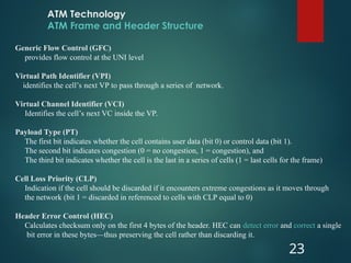
ATM Routing
Acell of 53 bytes is used as a data unit for transfer.
ATM uses two types of connections: a permanent virtual circuit (PVC) and a
Switch Virtual Circuit (SVC).
ATM uses switches to route the cell from one source endpoint to the
destination
A switch routes the cell using both the VPIs and the VCIs.
24
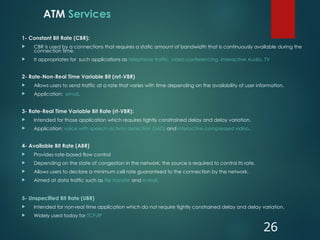
ATM Services
1- ConstantBit Rate (CBR):
CBR is used by a connections that requires a static amount of bandwidth that is continuously available during the
connection time.
It appropriates for such applications as telephone traffic, video conferencing, interactive Audio, TV
2- Rate-Non-Real Time Variable Bit (nrt-VBR)
Allows users to send traffic at a rate that varies with time depending on the availability of user information.
Application: email.
3- Rate-Real Time Variable Bit Rate (rt-VBR):
Intended for those application which requires tightly constrained delay and delay variation.
Application: voice with speech activity detection (SAD) and interactive compressed video.
4- Available Bit Rate (ABR)
Provides rate-based flow control
Depending on the state of congestion in the network, the source is required to control its rate.
Allows users to declare a minimum cell rate guaranteed to the connection by the network.
Aimed at data traffic such as file transfer and e-mail.
5- Unspecified Bit Rate (UBR)
Intended for non-real time application which do not require tightly constrained delay and delay variation.
Widely used today for TCP/IP
26
27.
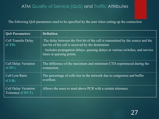
ATM Quality ofService (QoS) and Traffic Attributes
27
The following QoS parameters need to be specified by the user when setting up the connection
QoS Parameters Definition
Cell Transfer Delay
(CTD)
-The delay between the first bit of the cell is transmitted by the source and the
last bit of the cell is received by the destination
- Includes propagation delays, queuing delays at various switches, and service
times at queuing points.
Cell Delay Variation
(CDV)
The difference of the maximum and minimum CTD experienced during the
connection.
Cell Lost Ratio
(CLR)
The percentage of cells lost in the network due to congestion and buffer
overflow.
Cell Delay Variation
Tolerance (CDVT)
Allows the users to send above PCR with a certain tolerance.
28.
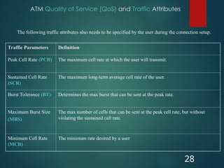
ATM Quality ofService (QoS) and Traffic Attributes
28
Traffic Parameters Definition
Peak Cell Rate (PCR) The maximum cell rate at which the user will transmit.
Sustained Cell Rate
(SCR)
The maximum long-term average cell rate of the user.
Burst Tolerance (BT) Determines the max burst that can be sent at the peak rate.
Maximum Burst Size
(MBS)
The max number of cells that can be sent at the peak cell rate, but without
violating the sustained cell rate.
Minimum Cell Rate
(MCR)
The minimum rate desired by a user
The following traffic attributes also needs to be specified by the user during the connection setup.
29.
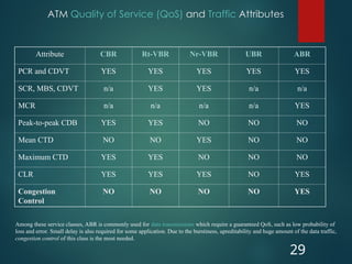
ATM Quality ofService (QoS) and Traffic Attributes
29
Attribute CBR Rt-VBR Nr-VBR UBR ABR
PCR and CDVT YES YES YES YES YES
SCR, MBS, CDVT n/a YES YES n/a n/a
MCR n/a n/a n/a n/a YES
Peak-to-peak CDB YES YES NO NO NO
Mean CTD NO NO YES NO NO
Maximum CTD YES YES NO NO NO
CLR YES YES YES NO YES
Congestion
Control
NO NO NO NO YES
Among these service classes, ABR is commonly used for data transmissions which require a guaranteed QoS, such as low probability of
loss and error. Small delay is also required for some application. Due to the burstiness, upreditability and huge amount of the data traffic,
congestion control of this class is the most needed.
30.
ATM Congestion Control
Support a set of QoS parameters and classes for all ATM services
Minimize network and en-system complexity while maximizing the network
utilization.
30
Objectives of Congestion Control ?
31.
ATM Congestion Control
Congestionhappens whenever the input rate is more that the available link capacity:
Sum (input rate) > Available Link Capacity
The traffic management working group was started in the Forum in May 1993– with
main duties to establish a mechanism for congestion control.
There were a number of congestion schemes were presented– these are
1. Fast Resource Management,
2. Delay-Based Rate Control,
3. Backward Explicit Congestion Notification (BECN),
4. Early Packet Discard,
5. Link Window with End-to-End Binary Rate,
6. Fair Queuing with Rate and Buffer feedback,
7. Credit-Based Approach and
8. Rate-Based Approach.
However, the working group selected two key proposals – Credit-Based Approach and
Rate-Based Approach– for the forum to make decision.
After a considerable debate which lasts for over a year, ATM Form adopted the Rate-
Based Approach and rejected the credit-based approach.
31
32.
ATM Congestion Control
Thefollowing is the main selection criteria used to sort out the above proposal:
1- Scalability:
The scheme should not be limited to a particular range of speed, distance, number of
switches, or number of VCs. The scheme should be applicable for both LAN and
WAN.
2- Optimality
A fair share of bandwidth among sources, which is based on such fairness criteria as
Max-Min
3- Fairness Index
The share of bandwidth for each source should be equal to or converge to the
optimal value according to some optimality criterion.
4- Robustness
The scheme should be insensitive to minor deviations such as slight mistuning of
parameters or loss of control messages. It should also isolate misbehaving users and
protect other users from them.
5- Implementability
The scheme should not dictate a particular switch architecture. It also should not be
too complex both in term of time and space it uses.
32
33.
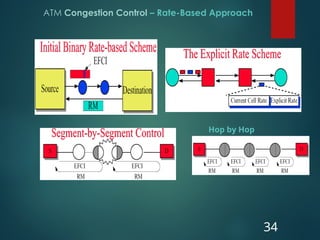
ATM Congestion Control– Rate-Based Approach
Rate-Based Approach’ basic concept:
This approach controls the rate by which the source can transmit.
If the network is light loaded, the source are allowed to increase its cell rate.
If the network is congested, the source should decrease its rate.
Switches monitor their queue lengths and if congested set Explicit Forward
Congestion Indicator (EFCI) to 1.
The destination monitors these indications for a periodic interval and sends a RM cell
back the source.
The sources use an additive increase and multiplicative decrease algorithm to adjust
their rates.
33
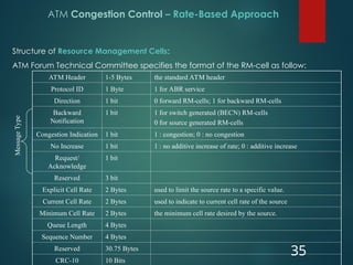
ATM Congestion Control– Rate-Based Approach
Structure of Resource Management Cells:
ATM Forum Technical Committee specifies the format of the RM-cell as follow:
35
ATM Header 1-5 Bytes the standard ATM header
Protocol ID 1 Byte 1 for ABR service
Direction 1 bit 0 forward RM-cells; 1 for backward RM-cells
Backward
Notification
1 bit 1 for switch generated (BECN) RM-cells
0 for source generated RM-cells
Congestion Indication 1 bit 1 : congestion; 0 : no congestion
No Increase 1 bit 1 : no additive increase of rate; 0 : additive increase
Request/
Acknowledge
1 bit
Reserved 3 bit
Explicit Cell Rate 2 Bytes used to limit the source rate to a specific value.
Current Cell Rate 2 Bytes used to indicate to current cell rate of the source
Minimum Cell Rate 2 Bytes the minimum cell rate desired by the source.
Queue Length 4 Bytes
Sequence Number 4 Bytes
Reserved 30.75 Bytes
CRC-10 10 Bits
Message
Type
ATM Benefits
Revenueopportunities
Reduces infrastructure costs through efficient bandwidth management,
operational simplicity, and the consolidation of overlay networks.
High performance via hardware switching
Dynamic bandwidth for bursty traffic
37
38.
Conclusion
ATM is aflexible and powerful technology which integrates the cell-switching and
multiplexing functions, and enables transmissions over a variety of carrier system.
It’s designed for high performance multimedia networking, and suitable for bursty
traffic.
ATM technology is a powerful common platform for LAN and WAN to increase
productivity, to reduce costs and to implement new applications and service.
Thus, the potential demand for ATM is a direct result of the widespread of LANs and
WANs, massive demand for file transfers, and growing interest in “paperless
office” technologies.
The growing in multimedia market is another huge potentiality of ATM.
However, the success of ATM will be determined by two sequential events: first how
fast the
standard is finalized and then how fast can vendors bring ATM products to the
market.
38
39.
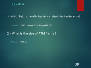
Question
1 - Whichfield in the ATM header can check the header error?
39
Answer : HEC – Header Error Control (HEC)
2 – What is the size of ATM frame ?
Answer : 53 Bytes
Editor's Notes
#7 Cell-based Transmission:
ATM divides all transmitted information into fixed-size packets called cells.
Each ATM cell is 53 bytes long — 5 bytes for the header and 48 bytes for the payload (data).
The fixed size allows for predictable transmission delay and efficient switching.
Asynchronous Operation
Unlike synchronous systems, ATM does not transmit data at regular intervals.
Cells are sent only when data is available, making bandwidth usage more efficient.
Connection-Oriented Service
A virtual circuit (either Permanent Virtual Circuit – PVC or Switched Virtual Circuit – SVC) must be set up before communication.
Ensures Quality of Service (QoS) and reliable delivery.
Scalability and Flexibility
Can handle speeds from a few Mbps to multiple Gbps.
Suitable for Local Area Networks (LANs), Wide Area Networks (WANs), and metropolitan networks.