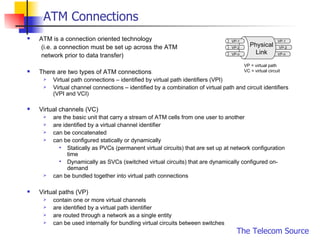
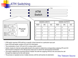
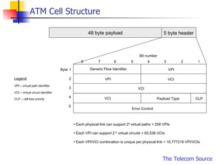
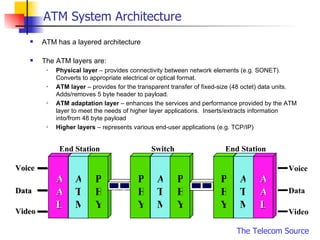
ATM The Telecom Source 10 Slide Technology Series
Introduction ATM stands for  A synchronous  T ransfer  M ode ATM is a flexible high bandwidth, low delay network technology that is: Capable of handling voice, video and data on a single network; and Generally used in the backbone  ATM has been evolving for over two decades Significant work for ATM begun in the early 1980’s Work culminated in 1988 as a series of standards forming part of the B-ISDN (Broadband Integrated Services Digital Network) Major advantages of ATM include: Bandwidth management capabilities; and Support for Quality of Service (QoS) features SONET/SDH was defined for the transport of ATM cells
ATM Connections ATM is a connection oriented technology (i.e. a connection must be set up across the ATM  network prior to data transfer) There are two types of ATM connections Virtual path connections – identified by virtual path identifiers (VPI) Virtual channel connections – identified by a combination of virtual path and circuit identifiers (VPI and VCI) Virtual channels (VC) are the basic unit that carry a stream of ATM cells from one user to another are identified by a virtual channel identifier can be concatenated can be configured statically or dynamically Statically as PVCs (permanent virtual circuits) that are set up at network configuration time Dynamically as SVCs (switched virtual circuits) that are dynamically configured on-demand can be bundled together into virtual path connections Virtual paths (VP) contain one or more virtual channels are identified by a virtual path identifier are routed through a network as a single entity can be used internally for bundling virtual circuits between switches VP-1 VP-2 VP-n VP-1 VP-2 VP-n Physical Link VP = virtual path VC = virtual circuit
ATM Switching ATM  Switch VP-1 VP-2 VP-n Physical  Link VC-1 VC-2 VC-n VC-1 VC-2 VC-n Port ATM switch receives ATM cell from a specific virtual channel on a particular input port Each ATM cell header contains VPI and VCI information The combination of port, VPI and VCI is unique within a switch Switch checks its internal routing table (local to the switch) to determine corresponding outgoing VPI and VCI that should be assigned to the cell and the output port on which the cell should be forwarded. The switch replaces the incoming VPI/VCI header info with the outgoing VPI/VCI info and sends the cell through the output port to the next device The process is repeated across multiple devices until the cell reaches its destination 10 2 2 2 1 1 1 2 2 1 1 1 … … … … … … 1 1 3 1 1 2 1 1 2 1 2 1 VCI VPI PORT VCI VPI PORT EGRESS (OUTPUT) INGRESS (INPUT)
ATM Cell Structure 48 byte payload 5 byte header Byte 1 2 3 4 5 1 2 3 4 5 6 7 8 Error Control VCI Generic Flow Identifier VPI VPI VCI VCI CLP Payload Type VPI – virtual path identifier VCI – virtual circuit identifier CLP – cell loss priority Legend Each physical link can support 2 8  virtual paths = 256 VPIs Each VPI can support 2 16  virtual circuits = 65,536 VCIs Each VPI/VCI combination is unique per physical link = 16,777216 VPI/VCIs Bit number
ATM System Architecture ATM has a layered architecture The ATM layers are: Physical layer  – provides connectivity between network elements (e.g. SONET).  Converts to appropriate electrical or optical format. ATM layer  – provides for the transparent transfer of fixed-size (48 octet) data units. Adds/removes 5 byte header to payload. ATM adaptation layer  – enhances the services and performance provided by the ATM layer to meet the needs of higher layer applications.  Inserts/extracts information into/from 48 byte payload Higher layers  – represents various end-user applications (e.g. TCP/IP) End Station End Station Switch Voice Data Video AAL PHY PHY ATM PHY ATM PHY ATM AAL Voice Data Video
ATM Adaptation Layer (AAL) The AAL maps higher-level data (e.g. legacy technologies) onto ATM cells making the data suitable for transport through the ATM network and isolates higher layers from the ATM layer.  These functions are performed on the user side. The concept of  Service Classes  is used to define traffic corresponding to specific combinations of:  timing relations between source and destination (required/not required) constant vs. variable bit rate connection mode (connection oriented vs. connectionless oriented) Defined service classes are: Class A – synchronous, connection oriented, constant bit rate (e.g. DS, DS3 circuit emulation) Class B – synchronous, connection oriented variable bit rate (e.g. packet video) Class C – asynchronous, connection oriented, variable bit rate (e.g. frame relay) Class D – asynchronous, connectionless, variable bit rate (e.g. SMDS) AAL protocols are defined to handle one of more of the above service classes and create properly formatted ATM cells.  There is no stipulation that rigidly binds an AAL protocol to a service class. AAL type 1  – meets the needs of class A services Provides for the acceptance of user info at a fixed rate and delivery of this info at the destination at the same fixed rate and indication of loss or errored information AAL type 2  – meets the needs of class B services Designed to carry low bit rate, variable-length, delay-sensitive packets  AAL type 3/4  - meets the needs of class C and D services Designed to carry variable bit rates with no timing relationship AAL type 5  – meets the needs of class C services Simplified and more efficient than 3/4 - simple and efficient data protocol
ATM Layer The ATM layer: provides services to higher layers (e.g. multiplexing ATM connections on to a single connection) and facilitates the forwarding of ATM cells through the network by the setting parameters in the ATM cell header (e.g. prioritization, traffic management).  delivers ATM cells to the physical layer for transport A number of parameters are set at the ATM layer that determine  quality of service  and  traffic management Quality of Service  (QoS) refers to a collection of performance parameters whose values have to do with the speed and accuracy/reliability characteristics of the ATM connection.  Negotiable parameters   ppCDV – peak to peak cell transfer delay variation Max CTD – maximum cell transfer delay  CLR – cell loss ratio Non-negotiable parameters CER – cell error ratio CMR – cell mis-insertion rate SECBR – severely errored cell block ratio Traffic parameters  define characteristics of the traffic to be offered over the ATM connection.  PCR – peak cell rate SCR – sustainable cell rate MBS – maximum burst rate MCR – minimum cell rate ICR – initial cell rate
ATM Layer …cont’d Service categories  represent particular combinations of traffic parameters and QoS parameters.  These parameters are negotiated by users for a connection to meet the needs of higher-level applications. CBR  (constant bit rate) is intended to support real-time applications requiring tightly constrained delay variation (e.g. voice, video) RT-VBR  (real-time variable bit rate) is intended for real-time applications with bursty traffic NRT-VBR  (non-real-time variable bit rate) is intended for non-real-time applications with bursty traffic  UBR  (unspecified bit rate) represents a “best-effort service intended for non-real-time applications that do not require tightly constrained delay or delay variation and are tolerant to cell loss ABR  (available bit rate) is similar to UBR but enhanced to handle applications that require a minimum bandwidth requirement Service Category Matrix      PCR UBR    ABR     NRT-VBR       RT-VBR    CBR ICR MBS MBS SCR CLR maxCTD ppCDV Traffic Parameters QoS Parameters Service Categories
Physical Layer The physical layer is responsible for placing and removing cells from the physical transport medium.  Standards for physical interfaces to various media exist and are discussed later. SONET/SDH based transmission media are the most common for transmission of ATM.  The physical layer performs two types of functions: Functions associated with the structure or format of the info to be transmitted and other specific functions (e.g. multiplexing).  These functions are independent of the transmission medium. Functions associated with the transmission of signals over a particular medium (e.g. line coding for a particular medium).  These functions are dependent on the transmission medium.
ATM Interfaces The following ATM interfaces have been defined and standardized Private UNI  (user-network interface) – specification of the interface between a user’s device (e.g. a workstation) and a private ATM switch Private NNI  (network-network interface) – e.g. between private ATM switches needed to support the ATM infrastructure Public UNI  – specification of the interface between the user’s device and a provider of a public ATM service Public NNI  – interface between ATM switches in public carrier networks.   Also referred to as  B-ISSI  (broadband inter-switching system interface) when applied to the connection between two public switches of the same carrier Also referred to as  B-ICI  (broadband inter-carrier interface) when applied to the connection between two carriers networks Specifications exist that describe the details of these interface standards
The Telecom Source www. thetelecomsource .com Info@ thetelecomsource .com

10 Slides to ATM

  • 1.
    ATM The TelecomSource 10 Slide Technology Series
  • 2.
    Introduction ATM standsfor A synchronous T ransfer M ode ATM is a flexible high bandwidth, low delay network technology that is: Capable of handling voice, video and data on a single network; and Generally used in the backbone ATM has been evolving for over two decades Significant work for ATM begun in the early 1980’s Work culminated in 1988 as a series of standards forming part of the B-ISDN (Broadband Integrated Services Digital Network) Major advantages of ATM include: Bandwidth management capabilities; and Support for Quality of Service (QoS) features SONET/SDH was defined for the transport of ATM cells
  • 3.
    ATM Connections ATMis a connection oriented technology (i.e. a connection must be set up across the ATM network prior to data transfer) There are two types of ATM connections Virtual path connections – identified by virtual path identifiers (VPI) Virtual channel connections – identified by a combination of virtual path and circuit identifiers (VPI and VCI) Virtual channels (VC) are the basic unit that carry a stream of ATM cells from one user to another are identified by a virtual channel identifier can be concatenated can be configured statically or dynamically Statically as PVCs (permanent virtual circuits) that are set up at network configuration time Dynamically as SVCs (switched virtual circuits) that are dynamically configured on-demand can be bundled together into virtual path connections Virtual paths (VP) contain one or more virtual channels are identified by a virtual path identifier are routed through a network as a single entity can be used internally for bundling virtual circuits between switches VP-1 VP-2 VP-n VP-1 VP-2 VP-n Physical Link VP = virtual path VC = virtual circuit
  • 4.
    ATM Switching ATM Switch VP-1 VP-2 VP-n Physical Link VC-1 VC-2 VC-n VC-1 VC-2 VC-n Port ATM switch receives ATM cell from a specific virtual channel on a particular input port Each ATM cell header contains VPI and VCI information The combination of port, VPI and VCI is unique within a switch Switch checks its internal routing table (local to the switch) to determine corresponding outgoing VPI and VCI that should be assigned to the cell and the output port on which the cell should be forwarded. The switch replaces the incoming VPI/VCI header info with the outgoing VPI/VCI info and sends the cell through the output port to the next device The process is repeated across multiple devices until the cell reaches its destination 10 2 2 2 1 1 1 2 2 1 1 1 … … … … … … 1 1 3 1 1 2 1 1 2 1 2 1 VCI VPI PORT VCI VPI PORT EGRESS (OUTPUT) INGRESS (INPUT)
  • 5.
    ATM Cell Structure48 byte payload 5 byte header Byte 1 2 3 4 5 1 2 3 4 5 6 7 8 Error Control VCI Generic Flow Identifier VPI VPI VCI VCI CLP Payload Type VPI – virtual path identifier VCI – virtual circuit identifier CLP – cell loss priority Legend Each physical link can support 2 8 virtual paths = 256 VPIs Each VPI can support 2 16 virtual circuits = 65,536 VCIs Each VPI/VCI combination is unique per physical link = 16,777216 VPI/VCIs Bit number
  • 6.
    ATM System ArchitectureATM has a layered architecture The ATM layers are: Physical layer – provides connectivity between network elements (e.g. SONET). Converts to appropriate electrical or optical format. ATM layer – provides for the transparent transfer of fixed-size (48 octet) data units. Adds/removes 5 byte header to payload. ATM adaptation layer – enhances the services and performance provided by the ATM layer to meet the needs of higher layer applications. Inserts/extracts information into/from 48 byte payload Higher layers – represents various end-user applications (e.g. TCP/IP) End Station End Station Switch Voice Data Video AAL PHY PHY ATM PHY ATM PHY ATM AAL Voice Data Video
  • 7.
    ATM Adaptation Layer(AAL) The AAL maps higher-level data (e.g. legacy technologies) onto ATM cells making the data suitable for transport through the ATM network and isolates higher layers from the ATM layer. These functions are performed on the user side. The concept of Service Classes is used to define traffic corresponding to specific combinations of: timing relations between source and destination (required/not required) constant vs. variable bit rate connection mode (connection oriented vs. connectionless oriented) Defined service classes are: Class A – synchronous, connection oriented, constant bit rate (e.g. DS, DS3 circuit emulation) Class B – synchronous, connection oriented variable bit rate (e.g. packet video) Class C – asynchronous, connection oriented, variable bit rate (e.g. frame relay) Class D – asynchronous, connectionless, variable bit rate (e.g. SMDS) AAL protocols are defined to handle one of more of the above service classes and create properly formatted ATM cells. There is no stipulation that rigidly binds an AAL protocol to a service class. AAL type 1 – meets the needs of class A services Provides for the acceptance of user info at a fixed rate and delivery of this info at the destination at the same fixed rate and indication of loss or errored information AAL type 2 – meets the needs of class B services Designed to carry low bit rate, variable-length, delay-sensitive packets AAL type 3/4 - meets the needs of class C and D services Designed to carry variable bit rates with no timing relationship AAL type 5 – meets the needs of class C services Simplified and more efficient than 3/4 - simple and efficient data protocol
  • 8.
    ATM Layer TheATM layer: provides services to higher layers (e.g. multiplexing ATM connections on to a single connection) and facilitates the forwarding of ATM cells through the network by the setting parameters in the ATM cell header (e.g. prioritization, traffic management). delivers ATM cells to the physical layer for transport A number of parameters are set at the ATM layer that determine quality of service and traffic management Quality of Service (QoS) refers to a collection of performance parameters whose values have to do with the speed and accuracy/reliability characteristics of the ATM connection. Negotiable parameters ppCDV – peak to peak cell transfer delay variation Max CTD – maximum cell transfer delay CLR – cell loss ratio Non-negotiable parameters CER – cell error ratio CMR – cell mis-insertion rate SECBR – severely errored cell block ratio Traffic parameters define characteristics of the traffic to be offered over the ATM connection. PCR – peak cell rate SCR – sustainable cell rate MBS – maximum burst rate MCR – minimum cell rate ICR – initial cell rate
  • 9.
    ATM Layer …cont’dService categories represent particular combinations of traffic parameters and QoS parameters. These parameters are negotiated by users for a connection to meet the needs of higher-level applications. CBR (constant bit rate) is intended to support real-time applications requiring tightly constrained delay variation (e.g. voice, video) RT-VBR (real-time variable bit rate) is intended for real-time applications with bursty traffic NRT-VBR (non-real-time variable bit rate) is intended for non-real-time applications with bursty traffic UBR (unspecified bit rate) represents a “best-effort service intended for non-real-time applications that do not require tightly constrained delay or delay variation and are tolerant to cell loss ABR (available bit rate) is similar to UBR but enhanced to handle applications that require a minimum bandwidth requirement Service Category Matrix      PCR UBR    ABR     NRT-VBR       RT-VBR    CBR ICR MBS MBS SCR CLR maxCTD ppCDV Traffic Parameters QoS Parameters Service Categories
  • 10.
    Physical Layer Thephysical layer is responsible for placing and removing cells from the physical transport medium. Standards for physical interfaces to various media exist and are discussed later. SONET/SDH based transmission media are the most common for transmission of ATM. The physical layer performs two types of functions: Functions associated with the structure or format of the info to be transmitted and other specific functions (e.g. multiplexing). These functions are independent of the transmission medium. Functions associated with the transmission of signals over a particular medium (e.g. line coding for a particular medium). These functions are dependent on the transmission medium.
  • 11.
    ATM Interfaces Thefollowing ATM interfaces have been defined and standardized Private UNI (user-network interface) – specification of the interface between a user’s device (e.g. a workstation) and a private ATM switch Private NNI (network-network interface) – e.g. between private ATM switches needed to support the ATM infrastructure Public UNI – specification of the interface between the user’s device and a provider of a public ATM service Public NNI – interface between ATM switches in public carrier networks. Also referred to as B-ISSI (broadband inter-switching system interface) when applied to the connection between two public switches of the same carrier Also referred to as B-ICI (broadband inter-carrier interface) when applied to the connection between two carriers networks Specifications exist that describe the details of these interface standards
  • 12.
    The Telecom Sourcewww. thetelecomsource .com Info@ thetelecomsource .com