Downloaded 138 times


A local area network (LAN) uses wired connections to connect devices within a limited geographic area like a building or campus. Ethernet became the dominant wired LAN technology using carrier sense multiple access with collision detection (CSMA/CD) to regulate shared access to the transmission medium. Ethernet has evolved from 10 Mbps to 100 Mbps to 1 Gbps standards to meet increasing bandwidth demands. Key components of wired LANs include network adapters, cabling, connectors, switches/hubs, and software protocols. Other historical wired LAN technologies like Token Ring and Token Bus used token passing for medium access but have been largely replaced by Ethernet.
Introduction to LANs describing their geographical scope and historical methods like Ethernet using CSMA/CD.
Describes the six key components of wired LAN including network adapters, media, connectors, power supplies, hubs, switches, routers, and essential network software like TCP/IP.
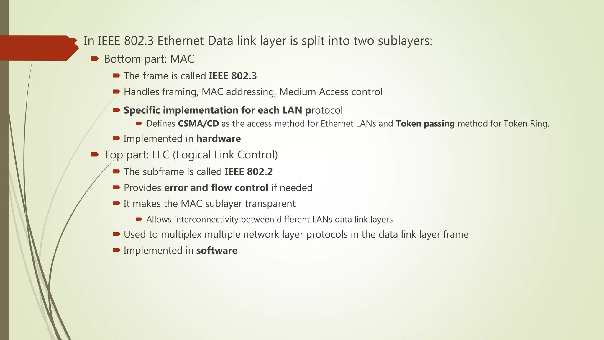
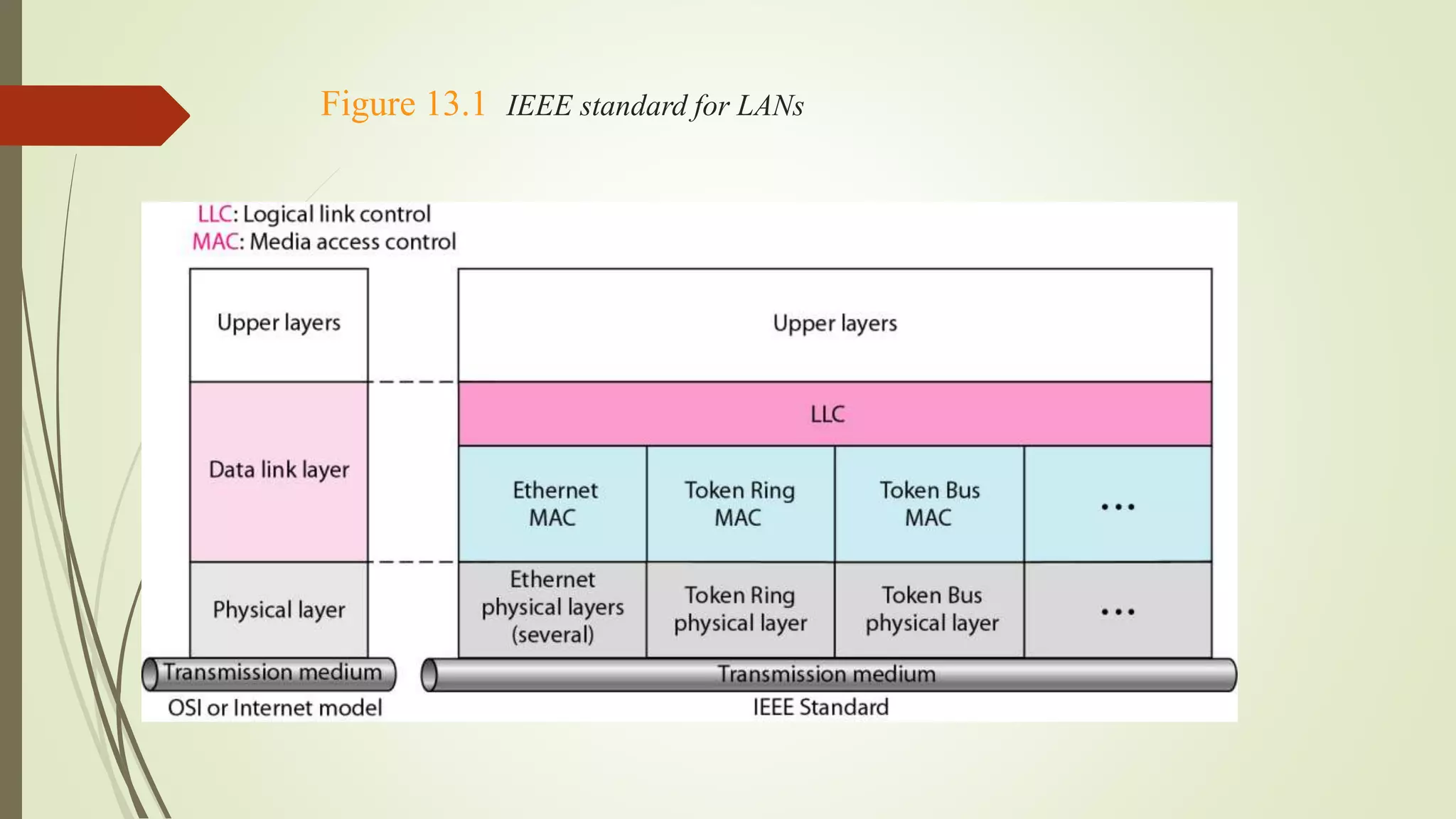
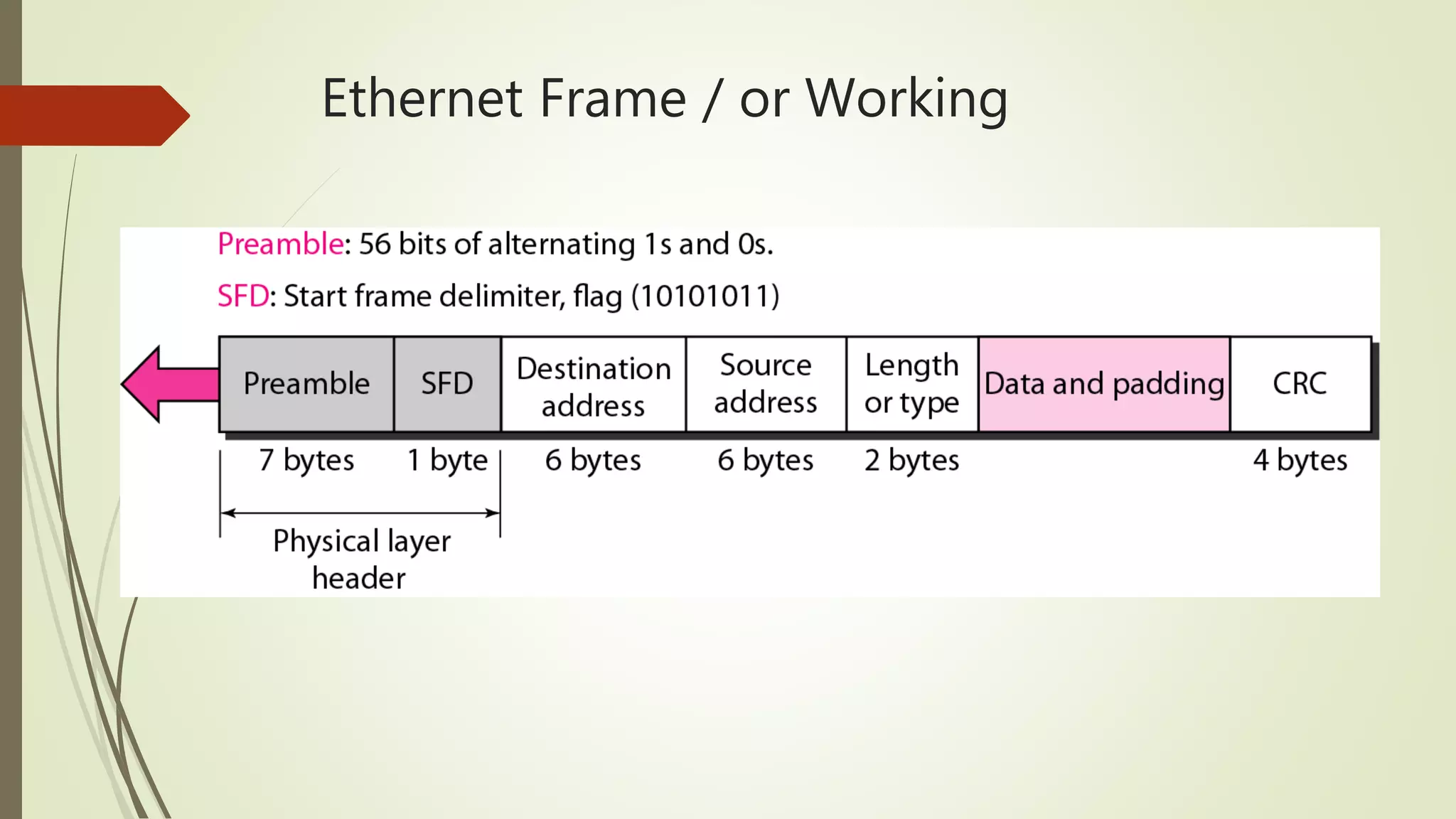
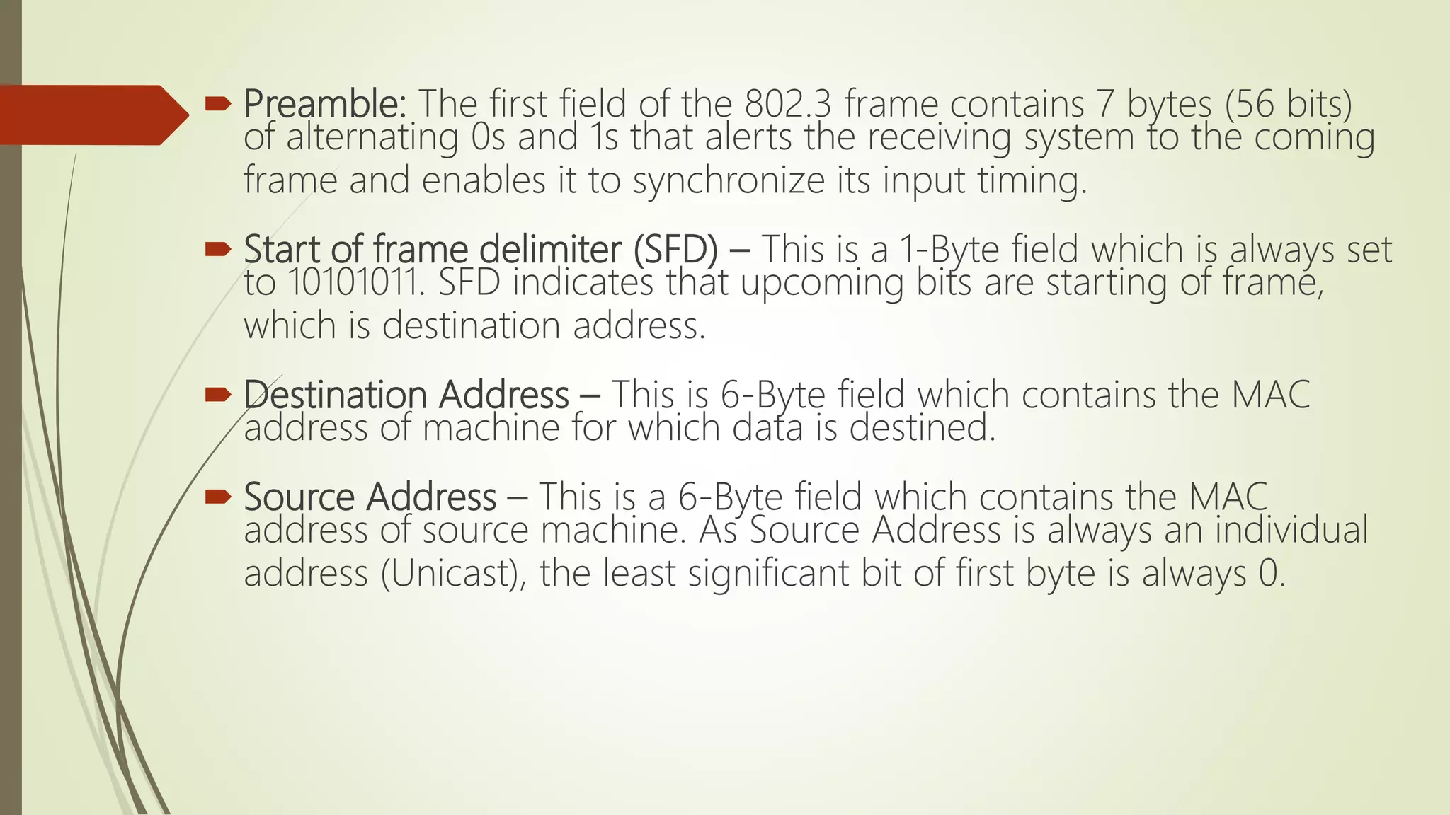
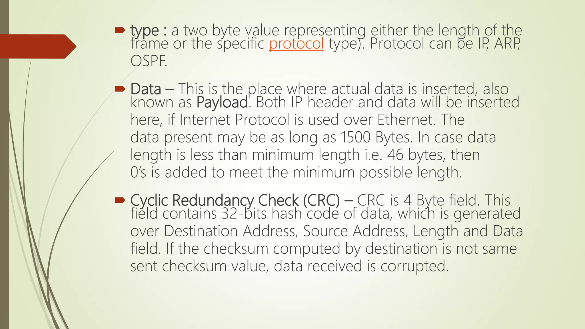
Overview of Ethernet technology, its IEEE standards, benefits, and the division between physical and data link layers.
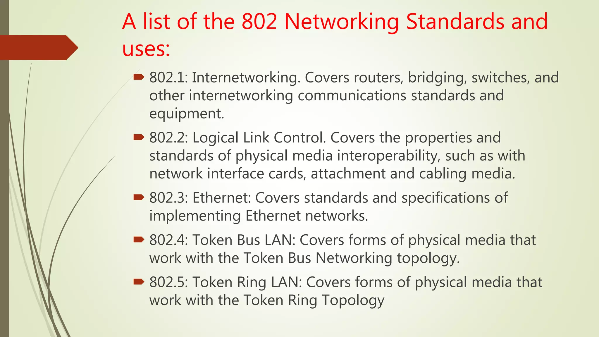
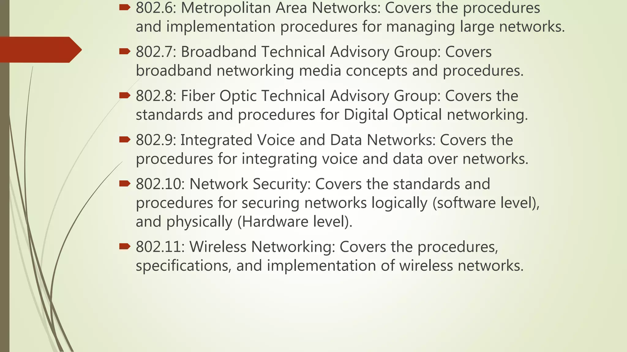
Details on Project 802 networking standards, highlighting various IEEE 802 standards relevant to different networking technologies.
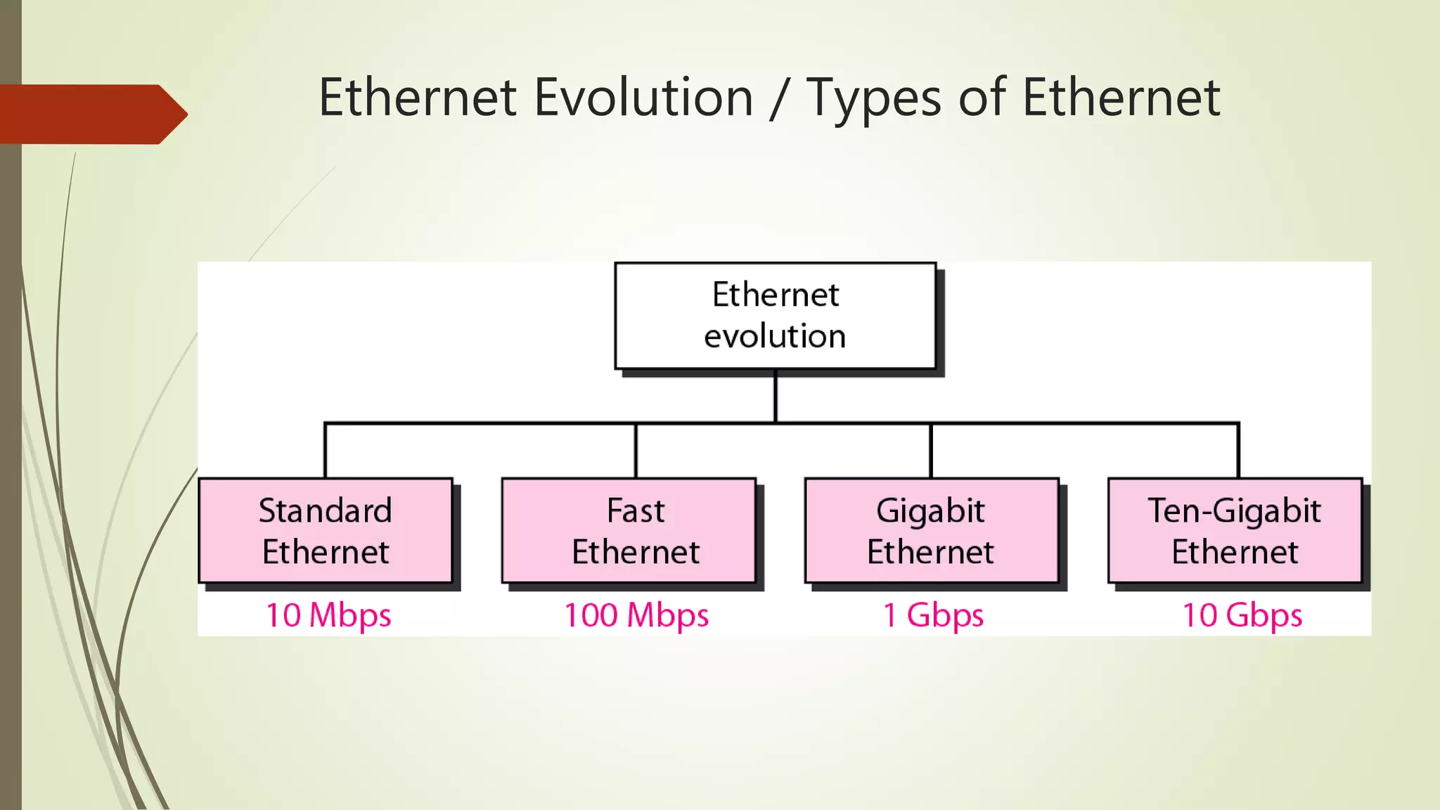
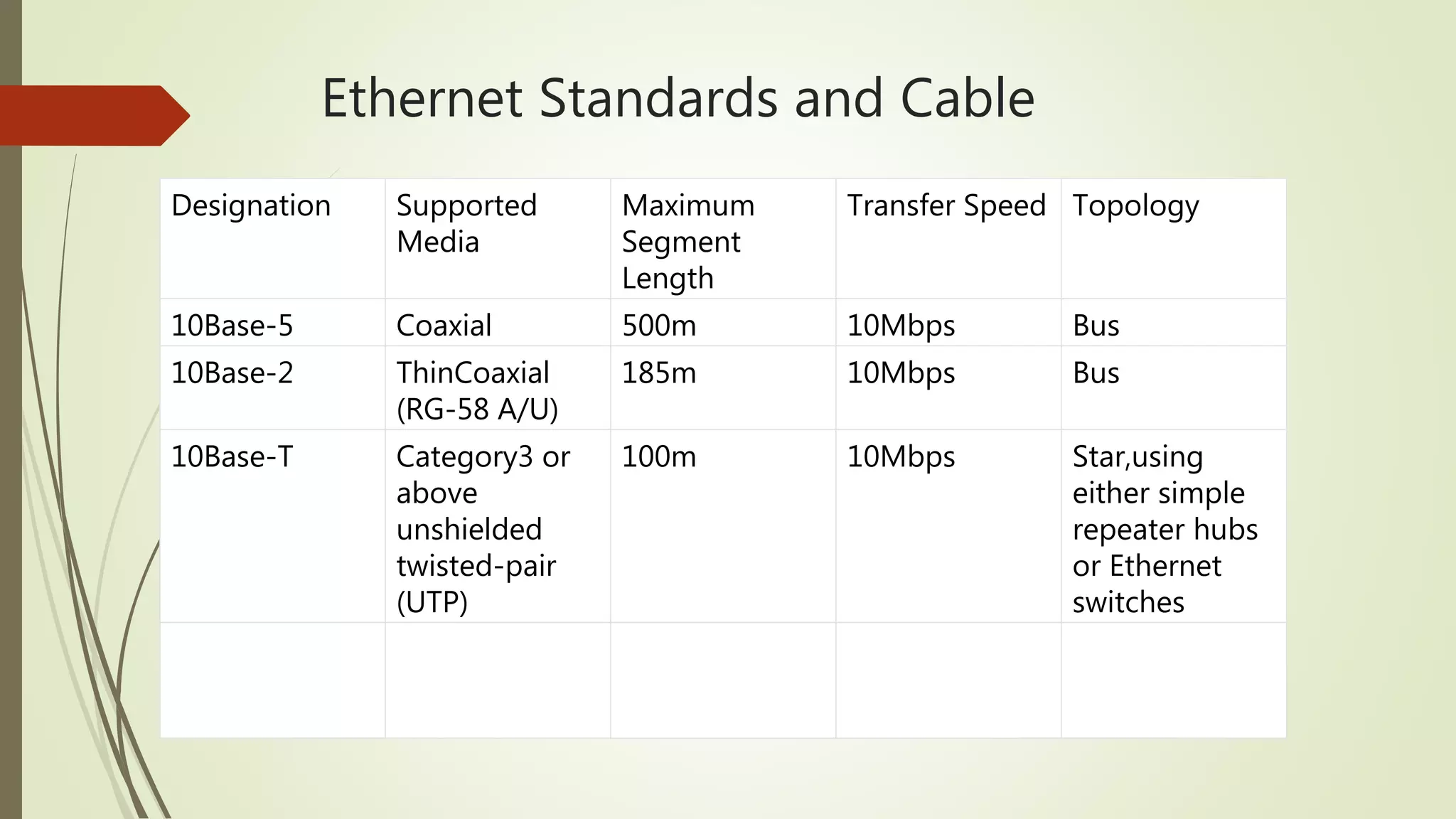
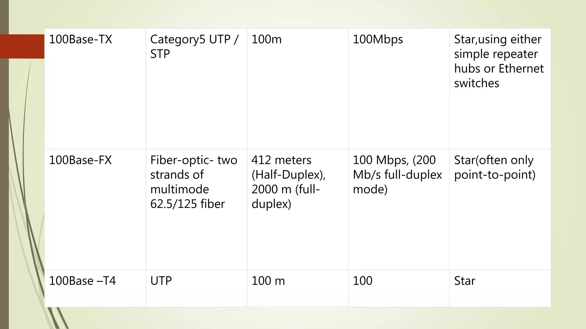
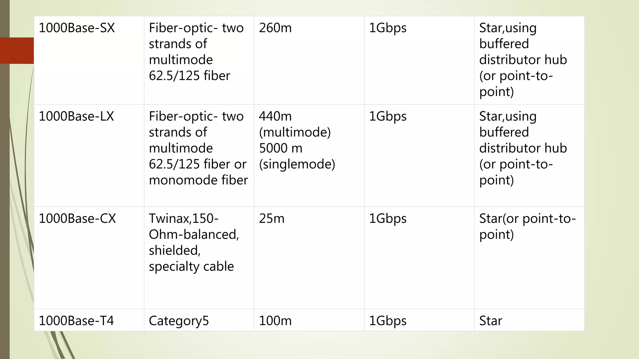
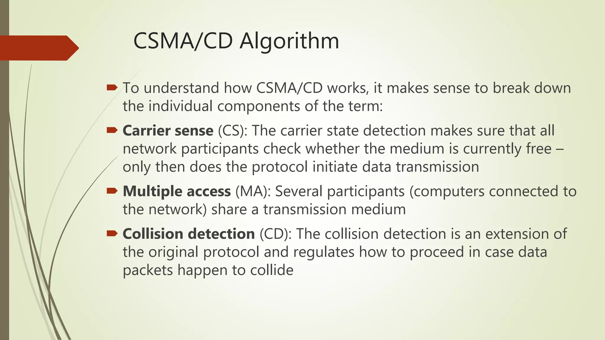
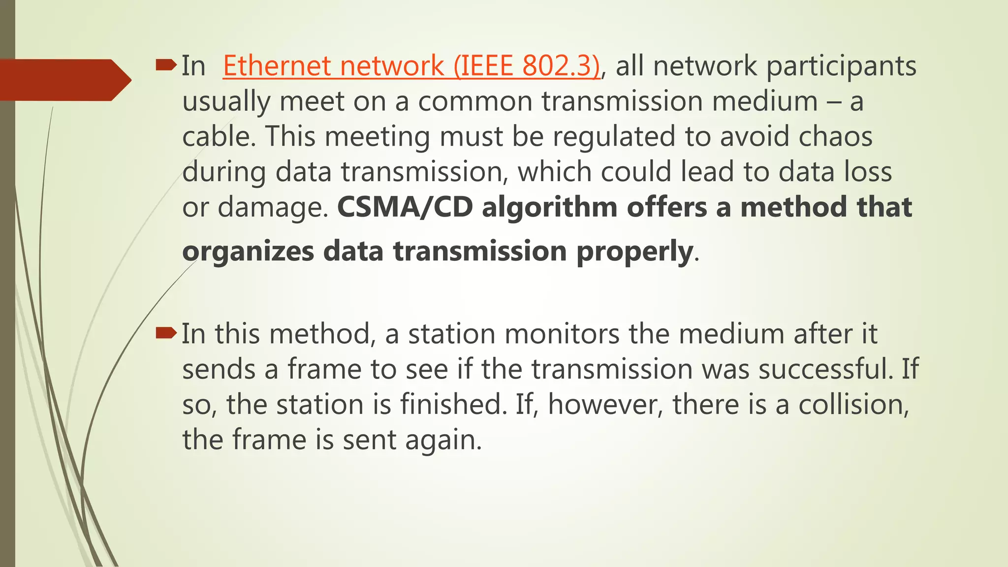
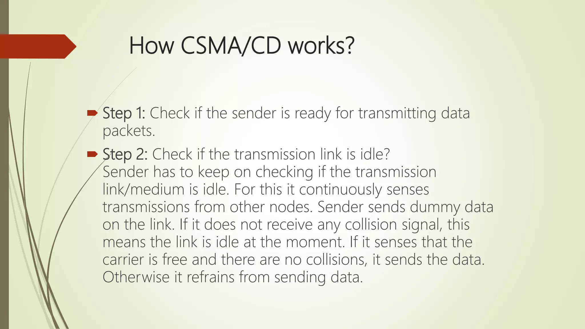
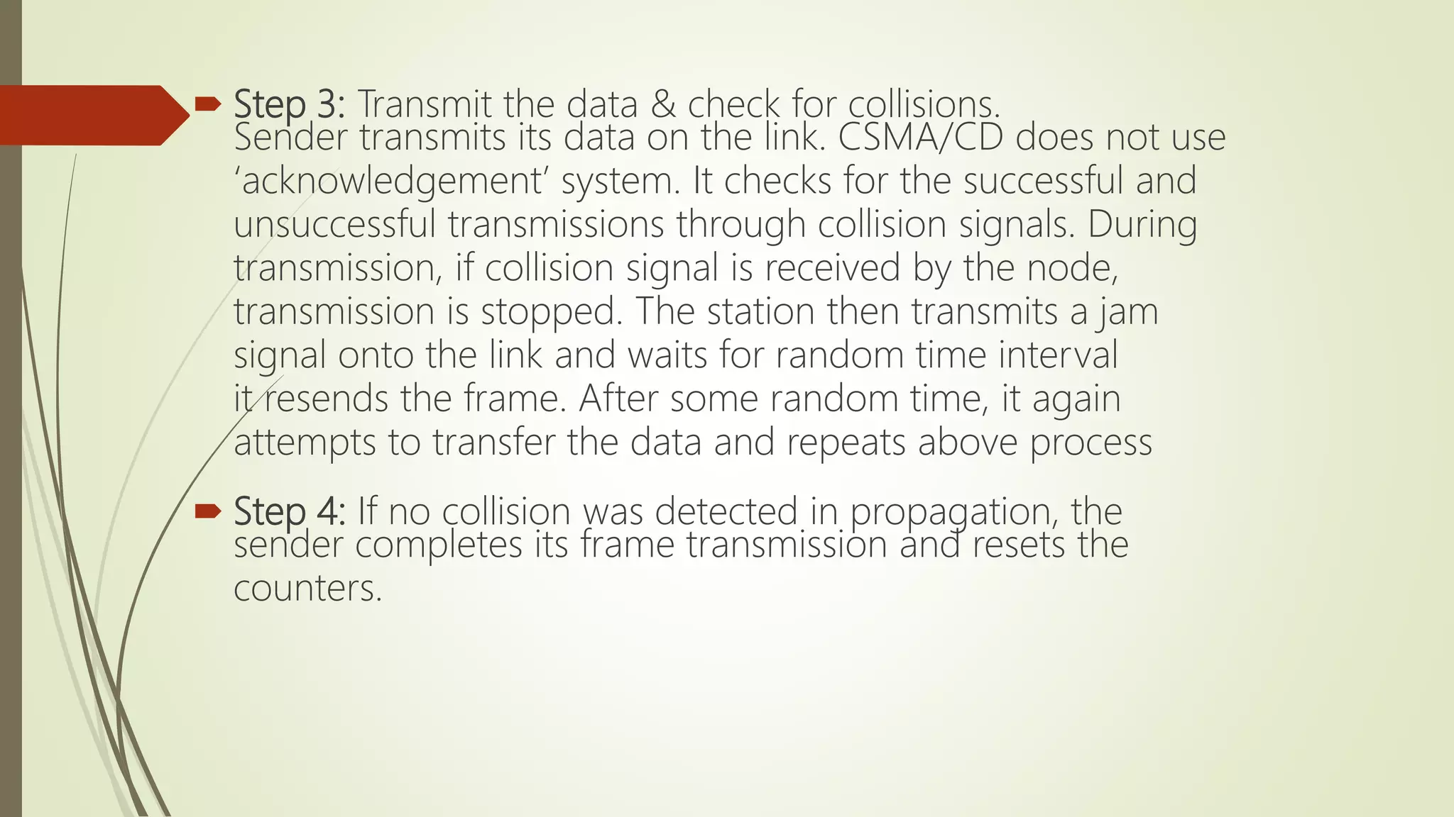
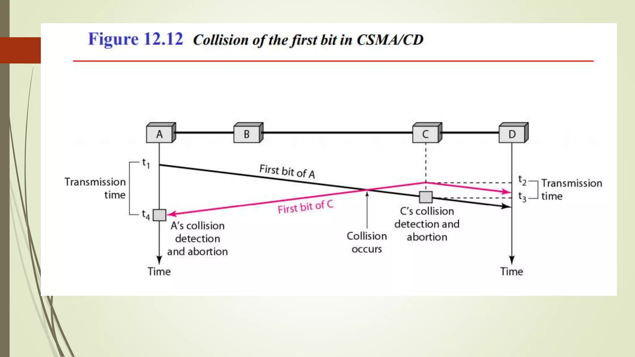
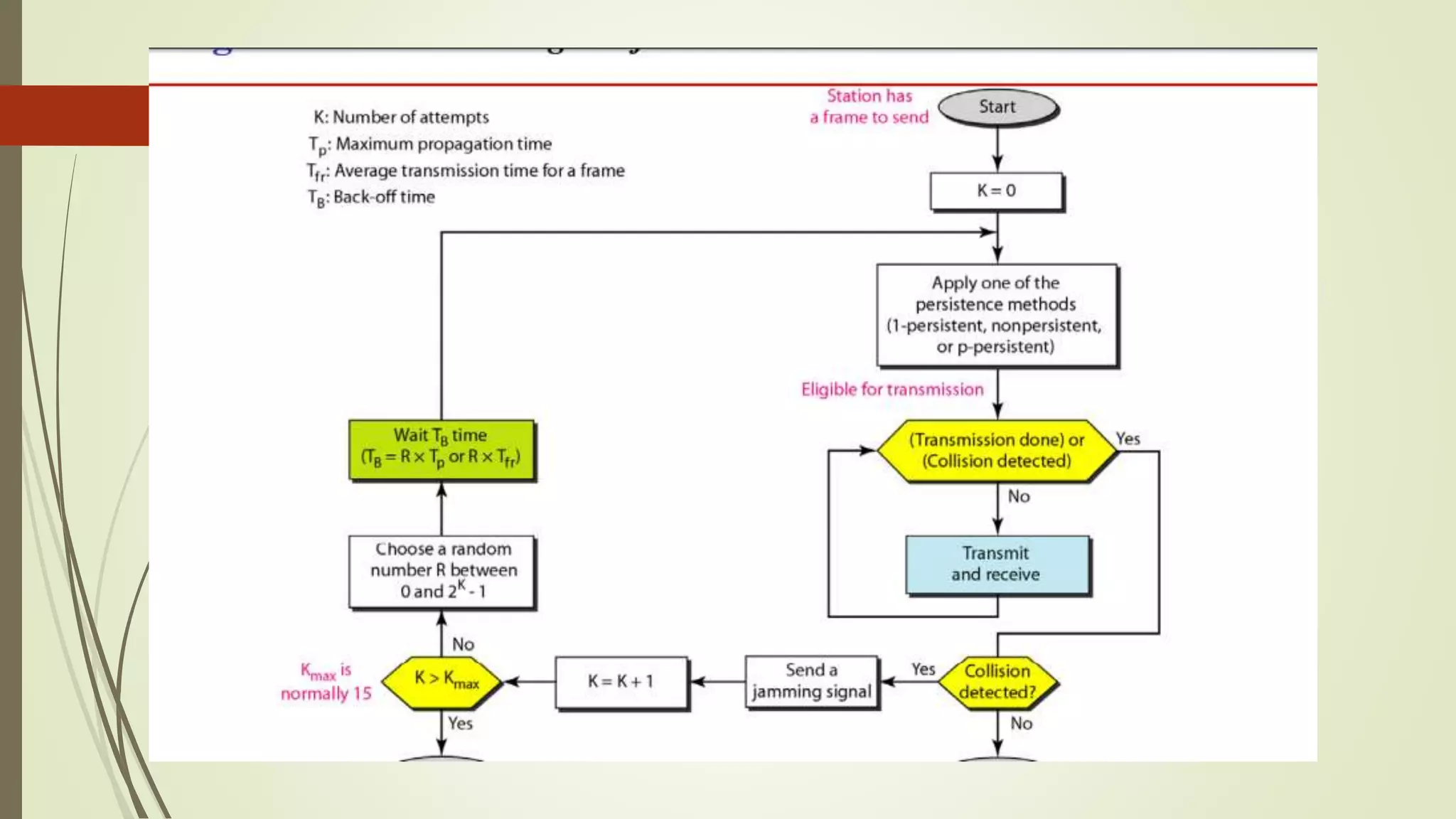
Discussion of the evolution of Ethernet including standard, fast, and gigabit Ethernet specifications and the CSMA/CD algorithm for data transmission.
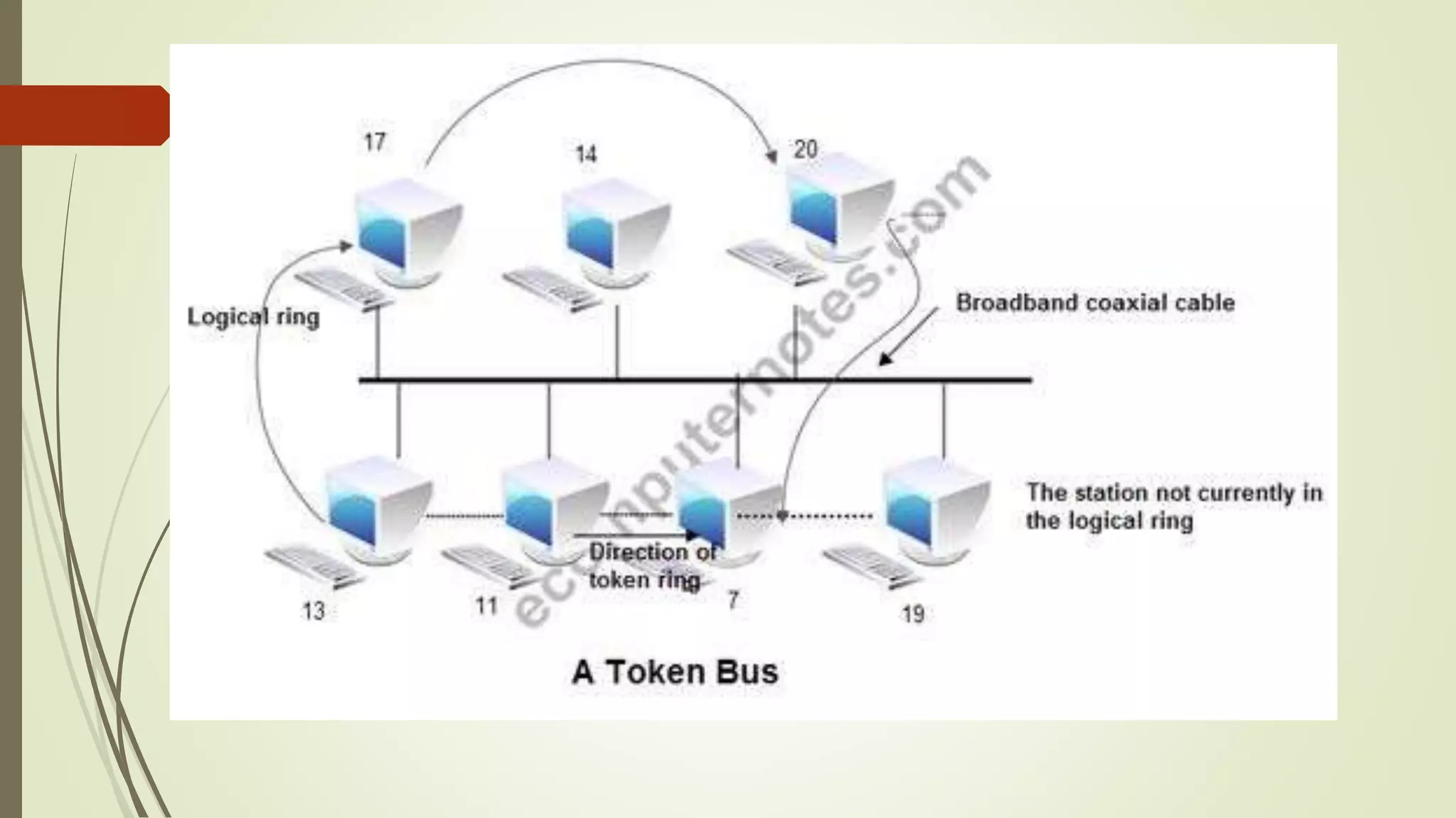
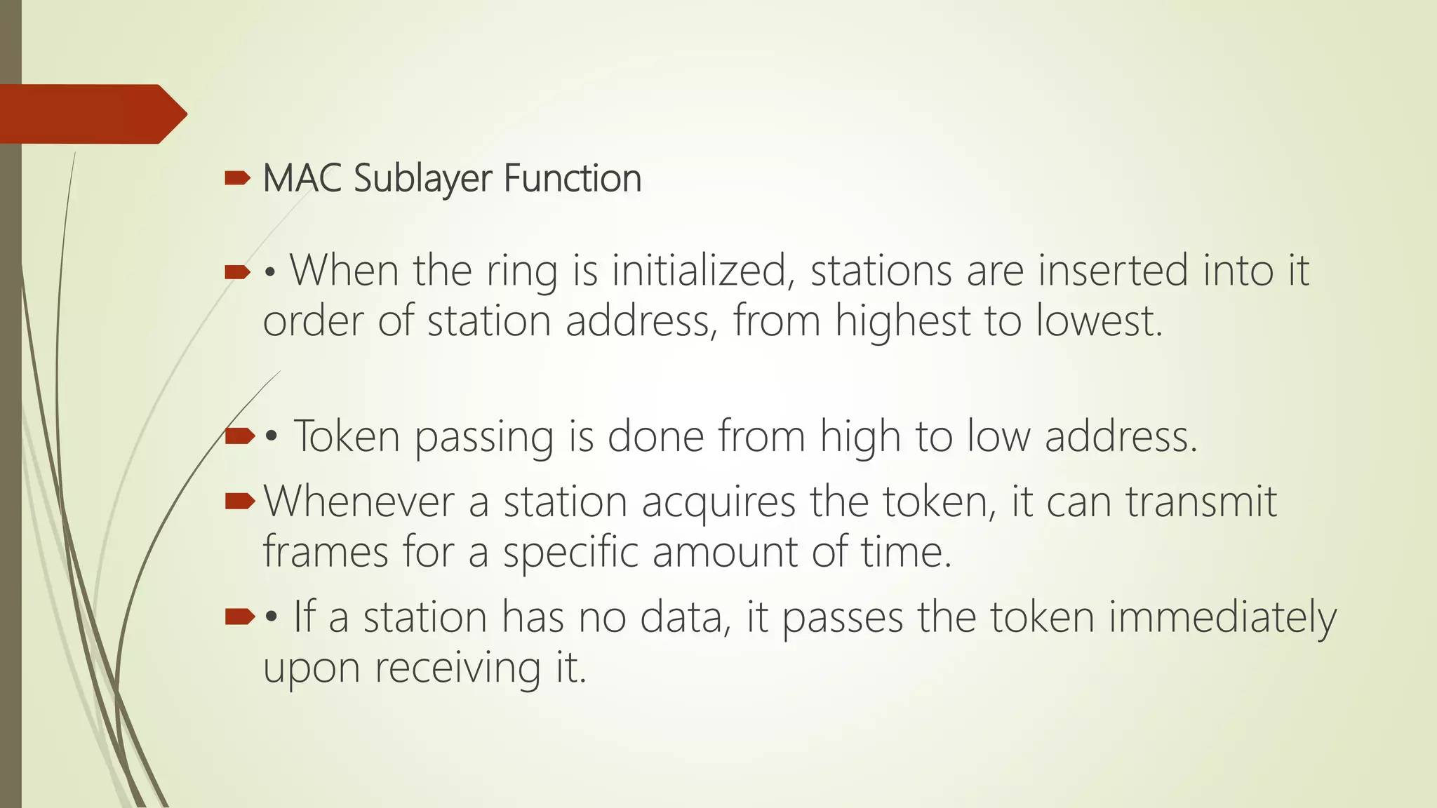
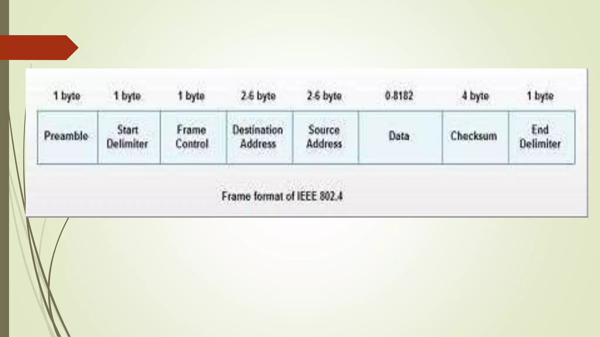
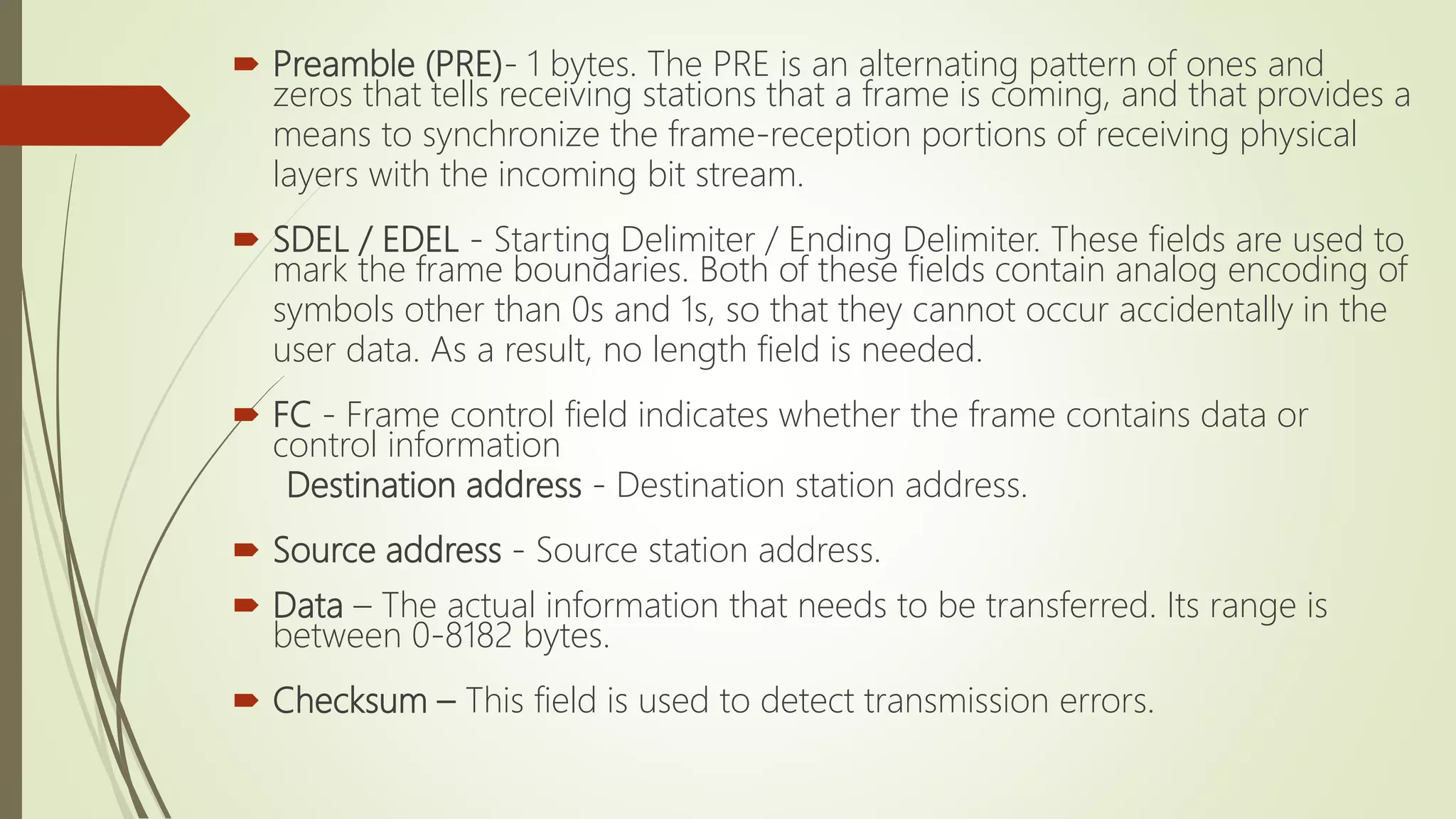
Description of the Token Bus LAN technology, its origins, operational principles, and how token passing facilitates data transmission.
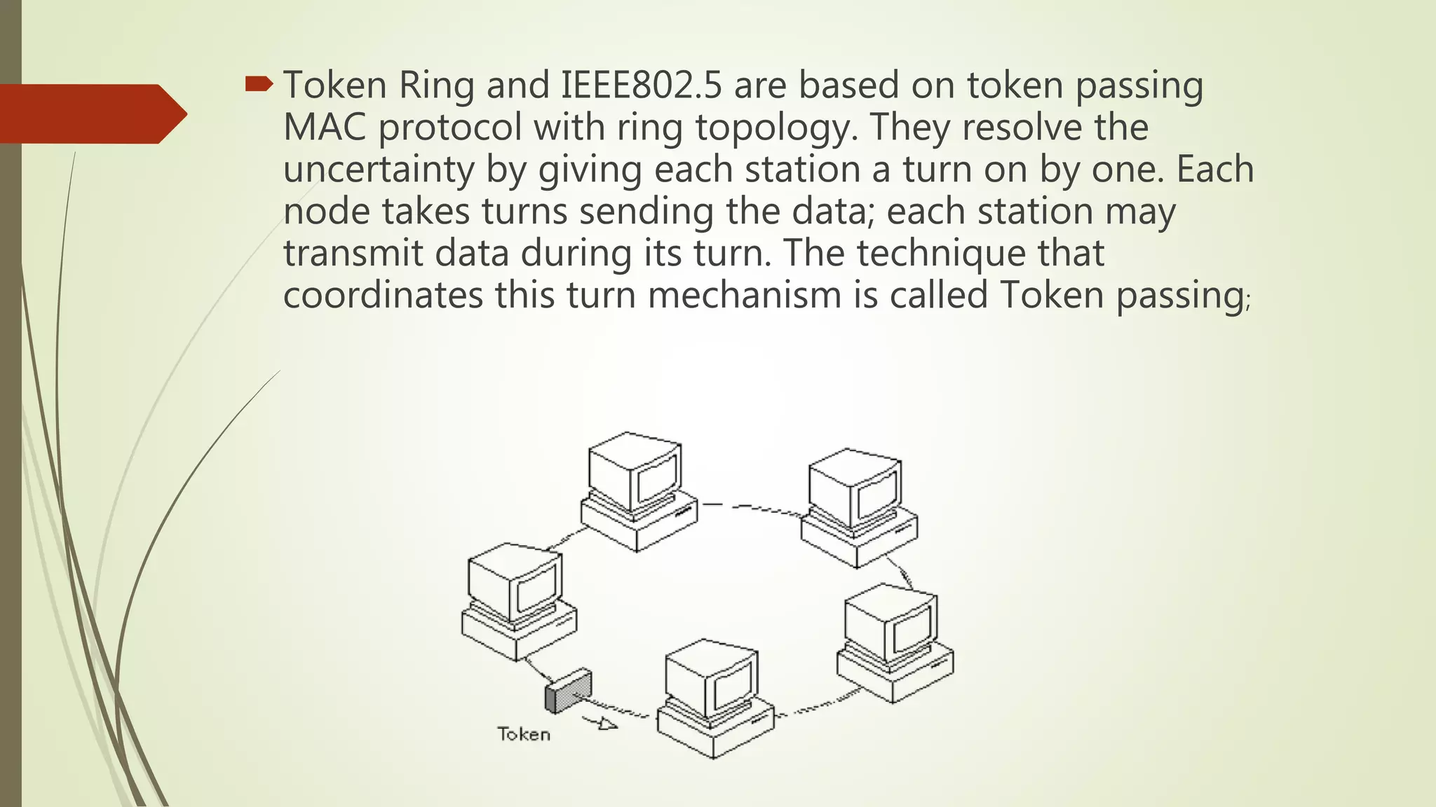
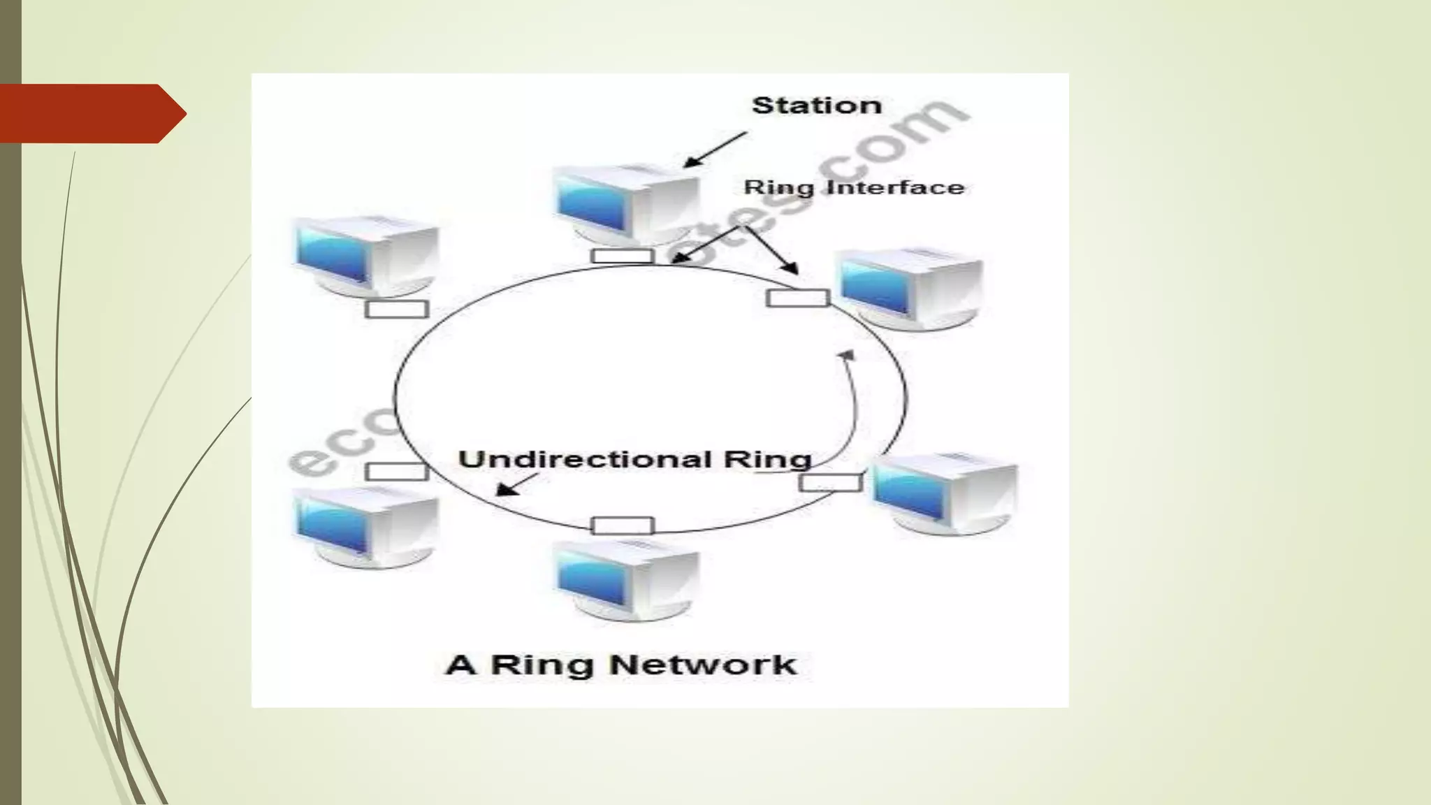
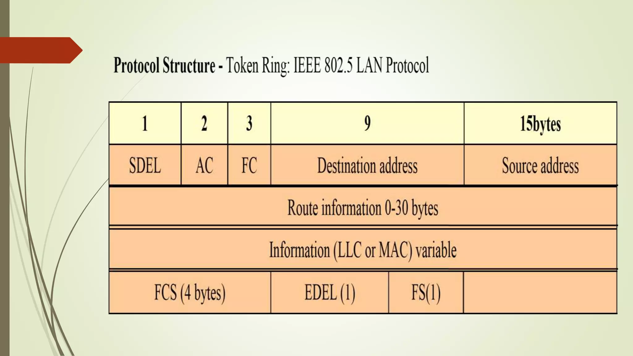
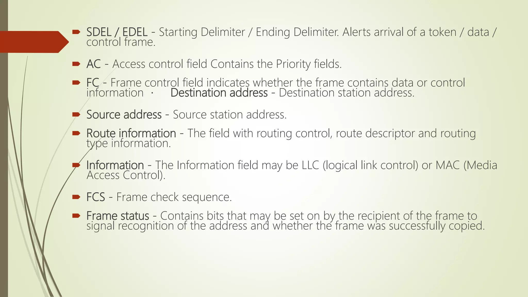
Explains the Token Ring LAN protocol, its token passing methodology, frame structure, and node management to avoid data transmission conflicts.