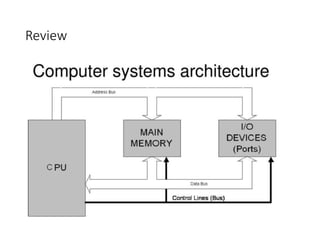
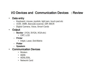
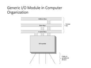
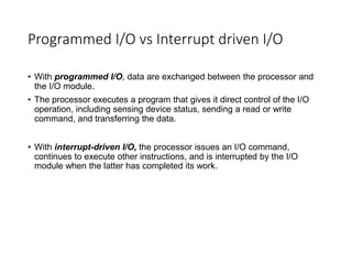
SlideShare a Scribd company logo
COMPUTER ARCHITECTURE
Data movement
& Logical Instructions
Lecture 09
Chap 7
Topics
I/O Devices
I/O Module Programmed I/O
Interrupt Driven I/O
Direct Memory Access
I/O Interface
I/O channels
Review
Computer Architecture
Generic I/O Module in Computer
Organization
Block Diagram of I/O Module
Module Functioning
THE I/O MODULE
FUNCTION
INVOLVES
CONTROL AND
TIMING
PROCESSOR
COMMUNICATION
DEVICE
COMMUNICATION
DATA BUFFERING ERROR DETECTION
Processor Communication
DECODING DATA STATUS
REPORTING
ADDRESS
RECOGNITION
Three Techniques of I/O Module
Programmed I/O Interrupt Driven
I/O
Direct Memory
Access
Commands of all three techniques
Programmed I/O vs Interrupt driven I/O
• With programmed I/O, data are exchanged between the processor and
the I/O module.
• The processor executes a program that gives it direct control of the I/O
operation, including sensing device status, sending a read or write
command, and transferring the data.
• With interrupt-driven I/O, the processor issues an I/O command,
continues to execute other instructions, and is interrupted by the I/O
module when the latter has completed its work.
Multiple I/O devices
• Typically, there will be many I/O devices connected through I/O modules
• Each device is given a unique identifier or address
• When the processor issues an I/O command, the command contains the
address of the desired device.
• When the processor, main memory, and I/O share a common bus, two
modes of addressing are possible: memory mapped and isolated
Memory Mapped I/O vs Isolated I/O
• With memory-mapped I/O, there is a single address space for memory
locations and I/O devices.
• The processor treats the status and data registers of I/O modules as
memory locations and uses the same machine instructions to access both
memory and I/O devices.
• With Isolated I/O, the bus may be equipped with memory read and write
plus input and output command lines.
• Now, the command line specifies whether the address refers to a memory
location or an I/O device.
Interrupt driven I/O
• The problem with
programmed I/O is that the
processor has to wait a
long time for the I/O
module of concern to be
ready for either reception
or transmission of data
• An alternative is for the
processor to issue an I/O
command to a module and
then go on to do some
other useful work, known
as Interrupt Driven I/O
operation
Design issues
• Two design issues occur in Interrupt Driven I/O operation
• First, because there will almost invariably be multiple I/O modules, how
does the processor determine which device issued the interrupt?
• second, if multiple interrupts have occurred, how does the processor
decide which one to process?
• To over come these issue interrupt controller is added to the processor
Interrupt controller (Intel 82C59A)
• The Intel 80386 provides a
single Interrupt Request
(INTR) and a single
Interrupt Acknowledge
(INTA) line
Drawbacks of Programmed and Interrupt-Driven I/O
1. The I/O transfer rate is limited by the speed with which the processor can
test and service a device.
2. The processor is tied up in managing an I/O transfer; a number of
instructions must be executed for each I/O transfer
Tradeoff between Programmed and Interrupt driven I/O
• When large volumes of data are to be moved, a more efficient technique is
required: direct memory access (DMA).
Direct Memory Access (DMA)
• Direct memory access (DMA) is a feature of computer systems that allows certain hardware
subsystems to access main system memory (random-access memory), independent of the central
processing unit (CPU).
• Direct Memory Access (DMA) is a capability provided by some computer bus architectures that allows
data to be sent directly from an attached device (such as a disk drive) to the memory on the
computer's motherboard.
• Without DMA, when the CPU is using Programmed Input/Output, it is typically fully occupied for the
entire duration of the read or write operation, and is thus unavailable to perform other work.
• With DMA, the CPU first initiates the transfer, then it does other operations while the transfer is in
progress, and it finally receives an interrupt from the DMA controller when the operation is done.
• This feature is useful when the CPU needs to perform work while waiting for a relatively slow I/O data
transfer.
• Many hardware systems use DMA, including disk drive controllers, graphics cards, network
cards and sound cards.
DMA
Basic DMA Technology
• DMA channel: system pathway used by a device to transfer
information directly to and from memory. There are usually 8 in a
computer system
• DMA controller: dedicated hardware used for controlling the DMA
operation
• Single-cycle mode: DMA data transfer is done one byte at a time
• Burst-mode: DMA transfer is finished when all data has been moved
Intel 8237 DMA Controller
• Intel 8237 is a direct memory access (DMA) controller, a part of the Intel
8085 microprocessor family.
• The Intel 8085 is an 8-bit microprocessor produced by Intel and introduced in 1976.
• It enables data transfer between memory and the I/O with reduced load on the system's
main processor during the DMA transfer.
• The 8237 is capable of DMA transfers at rates of up to 1.6 megabyte per second.
• A single 8237 was used as the DMA controller in the original IBM PC and IBM XT.
• Later IBM-compatible personal computers may have chip sets that emulate the functions of
the 8237 for backward compatibility.
• The 8237 is a four-channel device and each channel is capable of addressing a full 64k-byte
section of memory.
Intel 8237 DMA Operating Modes
• The 8237 operates in four different modes:
• Single mode
• In single mode, only one byte is transferred per request. For every transfer, the counting
register is decremented and address is incremented or decremented depending on
programming. When the counting register reaches zero, the terminal count TC signal is sent
to the card.
• The DMA request DREQ must be raised by the card and held active until it is acknowledged
by the DMA acknowledge DACK.
• Block transfer mode
• The transfer is activated by the DREQ which can be deactivated once acknowledged
by DACK. The transfer continues until end of process EOP (either internal or external) is
activated which will trigger terminal count TC to the card.
Intel 8237 DMA Operating Modes
• Demand transfer mode
• The transfer is activated by DREQ and acknowledged by DACK and continues until
either TC, external EOP or DREQ goes inactive.
• Cascade
• Used to cascade additional DMA controllers. DREQ and DACK is matched with HRQ and
HLDA from the next chip to establish a priority chain. Actual bus signals is executed by
cascaded chip.
• Cascade means to pass something onto others.
MEMORY-TO-MEMORY
• Memory-to-memory transfer can be performed. This means data can be transferred from
one memory device to another memory device.
I/O Interface (Interrupt and DMA Mode)
I/O Interface:
• The method that is used to transfer information between internal storage and external I/O devices is
known as I/O interface.
• Peripherals connected to a computer need special communication links for interfacing them with the
central processing unit.
• The purpose of communication link is to resolve the differences that exist between the central
computer and each peripheral.
• There exists special hardware components between CPU and peripherals to supervise and synchronize
all the input and output transfers that are called interface units.
• The Major Differences between External Devices and CPU and Memory are:-
• 1. Peripherals are electromechanical and electromagnetic devices and CPU and memory are electronic
devices. Therefore, a conversion of signal values may be needed.
• 2. The data transfer rate of peripherals is usually slower than the transfer rate of CPU and consequently,
a synchronization mechanism may be needed.
• 3. Data codes and formats in the peripherals differ from the word format in the CPU and memory.
• 4. The operating modes of peripherals are different from each other and must be controlled so as not to
disturb the operation of other peripherals connected to the CPU.
Interface Unit
• To Resolve these differences, computer systems include special hardware components between the CPU
and Peripherals to supervise and synchronize all input and output transfers.
• These components are called Interface Units because they interface between the processor bus and the
peripheral devices.
I/O Bus and Interface Unit
• It defines the typical link between the processor and several peripherals.
• The I/O Bus consists of data lines, address lines and control lines.
• The I/O bus from the processor is attached to interface module.
• To communicate with a particular device, the processor places a device address on address lines.
• Each Interface module decodes the address and control received from the I/O bus, interprets them for
peripherals and provides signals for the peripheral Controller.
• Interface Module also synchronizes the data flow and supervises the transfer between peripheral and
processor.
• Each peripheral has its own controller.
• EXAMPLE: the printer controller controls the paper motion, the print timing.
I/O Interface
Asynchronous Data Transfer: Strobe
• Asynchronous Data Transfer :
• This Scheme is used when speed of I/O devices do not match with microprocessor, and timing characteristics of I/O devices is not
predictable. In this method, process initiates the device and checks its status. As a result, CPU has to wait till I/O device is ready
to transfer data. When device is ready, CPU issues instruction for I/O transfer.
• In this method two types of techniques are used based on signals before data transfer.
• 1. Strobe Control
• 2. Handshaking
• Strobe Signal:
• The strobe control method of Asynchronous data transfer employs a single control line to time each transfer. The strobe may be
activated by either the source or the destination unit.
Source Initiated Strobe for Data Transfer:
• In the block diagram fig. (a), the data bus carries the binary information from source to destination unit. Typically, the bus has
multiple lines to transfer an entire byte or word. The strobe is a single line that informs the destination unit when a valid data
word is available.
• The timing diagram fig. (b) the source unit first places the data on the data bus. The information on the data bus and strobe signal
remain in the active state to allow the destination unit to receive the data.
Asynchronous Data Transfer: Strobe
Data Transfer Initiated by Destination Unit:
• In this method, the destination unit activates the strobe pulse, to inform the source to provide the data. The
source will respond by placing the requested binary information on the data bus.
• The data must be valid and remain in the bus long enough for the destination unit to accept it. When accepted,
the destination unit then disables the strobe and the source unit removes the data from the bus.
• Disadvantage of Strobe Signal:
• The disadvantage of the strobe method is that, the source unit that initiates the transfer (Part A on Previous
Slide) has no way of knowing whether the destination unit has actually received the data item that was placed
in the bus.
• Similarly, a destination unit that initiates the transfer (Part B on this Slide) has no way of knowing whether the
source unit has actually placed the data on bus.
• The Handshaking method solves this problem.
Asynchronous Data Transfer: Handshaking
• Handshaking:
• The handshaking method solves the problem of strobe method by introducing a second control signal
that provides a reply to the unit that initiates the transfer.
• Principle of Handshaking:
• One control line is in the same direction as the data flows in the bus from the source to destination. It is
used by source unit to inform the destination unit whether there is a valid data on the bus.
• The other control line is in the other direction from the destination to the source. It is used by the
destination unit to inform the source whether it can accept the data.
• The sequence of control during the transfer depends on the unit that initiates the transfer.
Asynchronous Data Transfer: Handshaking
• Source Initiated Transfer using Handshaking:
• The Fig (b) sequence of events shows four possible states that the system can be in at any given time.
• The source unit initiates the transfer by placing the data on the bus and enabling its data valid signal.
The data accepted signal is activated by the destination unit after it accepts the data from the bus. The
source unit then disables its data accepted signal and the system goes into its initial state.
Asynchronous Data Transfer: Handshaking
• Destination Initiated Transfer Using Handshaking:
• The name of the signal generated by the destination unit has been changed to ready for data in Fig (b) Sequence of events to
reflects its new meaning. The source unit in this case does not place data on the bus until after it receives the ready for data signal
from the destination unit. From there on, the handshaking procedure follows the same pattern as in the source initiated case.
• The only difference between the Source Initiated and the Destination Initiated transfer is in their choice of Initial state.
• Advantage of the Handshaking method:
• The Handshaking scheme provides degree of flexibility and reliability because the successful completion of data transfer relies on
active participation by both units.
• If any of one unit is faulty, the data transfer will not be completed. Such an error can be detected by means of a Timeout mechanism
which provides an alarm if the data is not completed within time.
Asynchronous Serial Transmission
• Asynchronous Serial Transmission:
• The transfer of data between two units is either serial or parallel. In parallel data transmission, n bits in
the message must be transmitted through n separate paths. In serial transmission, each bit in the
message is sent in sequence one at a time.
• Parallel transmission is faster but it requires many wires. It is used for short distances and where speed
is important. Serial transmission is slower but is less expensive.
• In Asynchronous serial transfer, each bit of message is sent in a sequence, and binary information is
transferred only when it is available. When there is no information to be transferred, line remains idle.
• In this technique each character consists of three points:
• i. Start bit
• ii. Character bit
• iii. Stop bit
Asynchronous Serial Transmission
• i. Start Bit- First bit, called start bit is always zero and used to indicate the beginning character.
• ii. Stop Bit- Last bit, called stop bit is always one and used to indicate end of characters. Stop bit is
always in the 1- state and represents the end of the characters to signify the idle or wait state.
• iii. Character Bit- Bits in between the start bit and the stop bit are known as character bits. The
character bits always follow the start bit.
• Serial Transmission of Asynchronous is done by two ways:
• a) Asynchronous Communication Interface
• b) First In First out Buffer
Asynchronous Serial Transmission Methods
• Asynchronous Communication Interface:
It works as both a receiver and a transmitter. Its operation is initialized by CPU by sending a byte to the
control register.
• The control register accepts a data byte from CPU through the data bus and transfer it to a shift register
for serial transmission.
• The receive portion receives data into another shift register, and when a complete data byte is received
it is transferred to receiver register.
• CPU can select the receiver register to read the byte through the data bus.
• First In First Out Buffer (FIFO):
• A First In First Out (FIFO) Buffer is a memory unit that stores information in such a manner that the first
item is in the item first out. A FIFO buffer comes with separate input and output terminals. The
important feature of this buffer is that it can input data and output data at two different rates.
• When placed between two units, the FIFO can accept data from the source unit at one rate, rate of
transfer and deliver the data to the destination unit at another rate.
• If the source is faster than the destination, the FIFO is useful for source data as it fills the buffer.
• FIFO is useful in some applications when data are transferred asynchronously.
Modes of Transfer (summary)
• Mode of Transfer:
• The binary information that is received from an external device is usually
stored in the memory unit. The information that is transferred from the CPU
to the external device is originated from the memory unit. CPU merely
processes the information but the source and target is always the memory
unit. Data transfer between CPU and the I/O devices may be done in
different modes.
• Data transfer to and from the peripherals may be done in any of the three
possible ways:
• Programmed I/O.
• Interrupt- initiated I/O.
• Direct memory access( DMA).

More Related Content

Similar to Lecture 9.pptx

Chapter 4
Chapter 4Chapter 4
Io techniques & its types
Io techniques & its typesIo techniques & its types
Io techniques & its typesNehal Naik
 
Hardware I/O organization
Hardware  I/O organization Hardware  I/O organization
Hardware I/O organization faria_khan
 
Input_Output_Organization.pptx
Input_Output_Organization.pptxInput_Output_Organization.pptx
Input_Output_Organization.pptx
SherinRappai
 
chapter7-input-output-COMPUTER organization.pdf
chapter7-input-output-COMPUTER organization.pdfchapter7-input-output-COMPUTER organization.pdf
chapter7-input-output-COMPUTER organization.pdf
SangitaBose2
 
comporgppt.pptx
comporgppt.pptxcomporgppt.pptx
comporgppt.pptx
FaisalAijaz1
 
Computer architecture input output organization
Computer architecture input output organizationComputer architecture input output organization
Computer architecture input output organization
Mazin Alwaaly
 
DMA Controller Presentation
DMA Controller PresentationDMA Controller Presentation
DMA Controller Presentation
WaddaMalik
 
ghgfjfhgdjfdhgdhgfdgfdhgdhgfdhgzeka.pptx
ghgfjfhgdjfdhgdhgfdgfdhgdhgfdhgzeka.pptxghgfjfhgdjfdhgdhgfdgfdhgdhgfdhgzeka.pptx
ghgfjfhgdjfdhgdhgfdgfdhgdhgfdhgzeka.pptx
EliasPetros
 
IO_ORGANIZATION.pdf
IO_ORGANIZATION.pdfIO_ORGANIZATION.pdf
IO_ORGANIZATION.pdf
GaganaPurshothama
 
COMPUTER ORGANIZATION NOTES Unit 3 4
COMPUTER ORGANIZATION NOTES  Unit 3 4COMPUTER ORGANIZATION NOTES  Unit 3 4
COMPUTER ORGANIZATION NOTES Unit 3 4
Dr.MAYA NAYAK
 
UNIT 2 8086 System Bus Structure.pptx
UNIT 2 8086 System Bus Structure.pptxUNIT 2 8086 System Bus Structure.pptx
UNIT 2 8086 System Bus Structure.pptx
Gowrishankar C
 
Chapter 1.pdf
Chapter 1.pdfChapter 1.pdf
Chapter 1.pdf
AnisZahirahAzman
 
discuss the drawbacks of programmed and interrupt driven io and des.pdf
discuss the drawbacks of programmed and interrupt driven io and des.pdfdiscuss the drawbacks of programmed and interrupt driven io and des.pdf
discuss the drawbacks of programmed and interrupt driven io and des.pdf
info998421
 
UNIT 2.pptx
UNIT 2.pptxUNIT 2.pptx
UNIT 2.pptx
BASKARS53
 
A transfer from I/O device to memory requires the execution of several instru...
A transfer from I/O device to memory requires the execution of several instru...A transfer from I/O device to memory requires the execution of several instru...
A transfer from I/O device to memory requires the execution of several instru...
rsaravanakumar13
 

Similar to Lecture 9.pptx (20)

Chapter 4
Chapter 4Chapter 4
Chapter 4
 
Cao u1
Cao u1Cao u1
Cao u1
 
Io techniques & its types
Io techniques & its typesIo techniques & its types
Io techniques & its types
 
Hardware I/O organization
Hardware  I/O organization Hardware  I/O organization
Hardware I/O organization
 
Input_Output_Organization.pptx
Input_Output_Organization.pptxInput_Output_Organization.pptx
Input_Output_Organization.pptx
 
chapter7-input-output-COMPUTER organization.pdf
chapter7-input-output-COMPUTER organization.pdfchapter7-input-output-COMPUTER organization.pdf
chapter7-input-output-COMPUTER organization.pdf
 
07 input output
07 input output07 input output
07 input output
 
comporgppt.pptx
comporgppt.pptxcomporgppt.pptx
comporgppt.pptx
 
Computer architecture input output organization
Computer architecture input output organizationComputer architecture input output organization
Computer architecture input output organization
 
DMA Controller Presentation
DMA Controller PresentationDMA Controller Presentation
DMA Controller Presentation
 
ghgfjfhgdjfdhgdhgfdgfdhgdhgfdhgzeka.pptx
ghgfjfhgdjfdhgdhgfdgfdhgdhgfdhgzeka.pptxghgfjfhgdjfdhgdhgfdgfdhgdhgfdhgzeka.pptx
ghgfjfhgdjfdhgdhgfdgfdhgdhgfdhgzeka.pptx
 
IO_ORGANIZATION.pdf
IO_ORGANIZATION.pdfIO_ORGANIZATION.pdf
IO_ORGANIZATION.pdf
 
COMPUTER ORGANIZATION NOTES Unit 3 4
COMPUTER ORGANIZATION NOTES  Unit 3 4COMPUTER ORGANIZATION NOTES  Unit 3 4
COMPUTER ORGANIZATION NOTES Unit 3 4
 
UNIT 2 8086 System Bus Structure.pptx
UNIT 2 8086 System Bus Structure.pptxUNIT 2 8086 System Bus Structure.pptx
UNIT 2 8086 System Bus Structure.pptx
 
Coa presentation4
Coa presentation4Coa presentation4
Coa presentation4
 
Chapter 1.pdf
Chapter 1.pdfChapter 1.pdf
Chapter 1.pdf
 
discuss the drawbacks of programmed and interrupt driven io and des.pdf
discuss the drawbacks of programmed and interrupt driven io and des.pdfdiscuss the drawbacks of programmed and interrupt driven io and des.pdf
discuss the drawbacks of programmed and interrupt driven io and des.pdf
 
UNIT 2.pptx
UNIT 2.pptxUNIT 2.pptx
UNIT 2.pptx
 
A transfer from I/O device to memory requires the execution of several instru...
A transfer from I/O device to memory requires the execution of several instru...A transfer from I/O device to memory requires the execution of several instru...
A transfer from I/O device to memory requires the execution of several instru...
 
E.s unit 4 and 5
E.s unit 4 and 5E.s unit 4 and 5
E.s unit 4 and 5
 

Recently uploaded

一比一原版(IIT毕业证)伊利诺伊理工大学毕业证成绩单专业办理
一比一原版(IIT毕业证)伊利诺伊理工大学毕业证成绩单专业办理一比一原版(IIT毕业证)伊利诺伊理工大学毕业证成绩单专业办理
一比一原版(IIT毕业证)伊利诺伊理工大学毕业证成绩单专业办理
zwunae
 
Standard Reomte Control Interface - Neometrix
Standard Reomte Control Interface - NeometrixStandard Reomte Control Interface - Neometrix
Standard Reomte Control Interface - Neometrix
Neometrix_Engineering_Pvt_Ltd
 
MCQ Soil mechanics questions (Soil shear strength).pdf
MCQ Soil mechanics questions (Soil shear strength).pdfMCQ Soil mechanics questions (Soil shear strength).pdf
MCQ Soil mechanics questions (Soil shear strength).pdf
Osamah Alsalih
 
Runway Orientation Based on the Wind Rose Diagram.pptx
Runway Orientation Based on the Wind Rose Diagram.pptxRunway Orientation Based on the Wind Rose Diagram.pptx
Runway Orientation Based on the Wind Rose Diagram.pptx
SupreethSP4
 
一比一原版(SFU毕业证)西蒙菲莎大学毕业证成绩单如何办理
一比一原版(SFU毕业证)西蒙菲莎大学毕业证成绩单如何办理一比一原版(SFU毕业证)西蒙菲莎大学毕业证成绩单如何办理
一比一原版(SFU毕业证)西蒙菲莎大学毕业证成绩单如何办理
bakpo1
 
Hierarchical Digital Twin of a Naval Power System
Hierarchical Digital Twin of a Naval Power SystemHierarchical Digital Twin of a Naval Power System
Hierarchical Digital Twin of a Naval Power System
Kerry Sado
 
space technology lecture notes on satellite
space technology lecture notes on satellitespace technology lecture notes on satellite
space technology lecture notes on satellite
ongomchris
 
ethical hacking-mobile hacking methods.ppt
ethical hacking-mobile hacking methods.pptethical hacking-mobile hacking methods.ppt
ethical hacking-mobile hacking methods.ppt
Jayaprasanna4
 
Railway Signalling Principles Edition 3.pdf
Railway Signalling Principles Edition 3.pdfRailway Signalling Principles Edition 3.pdf
Railway Signalling Principles Edition 3.pdf
TeeVichai
 
AKS UNIVERSITY Satna Final Year Project By OM Hardaha.pdf
AKS UNIVERSITY Satna Final Year Project By OM Hardaha.pdfAKS UNIVERSITY Satna Final Year Project By OM Hardaha.pdf
AKS UNIVERSITY Satna Final Year Project By OM Hardaha.pdf
SamSarthak3
 
J.Yang, ICLR 2024, MLILAB, KAIST AI.pdf
J.Yang,  ICLR 2024, MLILAB, KAIST AI.pdfJ.Yang,  ICLR 2024, MLILAB, KAIST AI.pdf
J.Yang, ICLR 2024, MLILAB, KAIST AI.pdf
MLILAB
 
weather web application report.pdf
weather web application report.pdfweather web application report.pdf
weather web application report.pdf
Pratik Pawar
 
English lab ppt no titlespecENG PPTt.pdf
English lab ppt no titlespecENG PPTt.pdfEnglish lab ppt no titlespecENG PPTt.pdf
English lab ppt no titlespecENG PPTt.pdf
BrazilAccount1
 
Nuclear Power Economics and Structuring 2024
Nuclear Power Economics and Structuring 2024Nuclear Power Economics and Structuring 2024
Nuclear Power Economics and Structuring 2024
Massimo Talia
 
Investor-Presentation-Q1FY2024 investor presentation document.pptx
Investor-Presentation-Q1FY2024 investor presentation document.pptxInvestor-Presentation-Q1FY2024 investor presentation document.pptx
Investor-Presentation-Q1FY2024 investor presentation document.pptx
AmarGB2
 
ASME IX(9) 2007 Full Version .pdf
ASME IX(9)  2007 Full Version       .pdfASME IX(9)  2007 Full Version       .pdf
ASME IX(9) 2007 Full Version .pdf
AhmedHussein950959
 
Student information management system project report ii.pdf
Student information management system project report ii.pdfStudent information management system project report ii.pdf
Student information management system project report ii.pdf
Kamal Acharya
 
ML for identifying fraud using open blockchain data.pptx
ML for identifying fraud using open blockchain data.pptxML for identifying fraud using open blockchain data.pptx
ML for identifying fraud using open blockchain data.pptx
Vijay Dialani, PhD
 
CME397 Surface Engineering- Professional Elective
CME397 Surface Engineering- Professional ElectiveCME397 Surface Engineering- Professional Elective
CME397 Surface Engineering- Professional Elective
karthi keyan
 
Water Industry Process Automation and Control Monthly - May 2024.pdf
Water Industry Process Automation and Control Monthly - May 2024.pdfWater Industry Process Automation and Control Monthly - May 2024.pdf
Water Industry Process Automation and Control Monthly - May 2024.pdf
Water Industry Process Automation & Control
 

Recently uploaded (20)

一比一原版(IIT毕业证)伊利诺伊理工大学毕业证成绩单专业办理
一比一原版(IIT毕业证)伊利诺伊理工大学毕业证成绩单专业办理一比一原版(IIT毕业证)伊利诺伊理工大学毕业证成绩单专业办理
一比一原版(IIT毕业证)伊利诺伊理工大学毕业证成绩单专业办理
 
Standard Reomte Control Interface - Neometrix
Standard Reomte Control Interface - NeometrixStandard Reomte Control Interface - Neometrix
Standard Reomte Control Interface - Neometrix
 
MCQ Soil mechanics questions (Soil shear strength).pdf
MCQ Soil mechanics questions (Soil shear strength).pdfMCQ Soil mechanics questions (Soil shear strength).pdf
MCQ Soil mechanics questions (Soil shear strength).pdf
 
Runway Orientation Based on the Wind Rose Diagram.pptx
Runway Orientation Based on the Wind Rose Diagram.pptxRunway Orientation Based on the Wind Rose Diagram.pptx
Runway Orientation Based on the Wind Rose Diagram.pptx
 
一比一原版(SFU毕业证)西蒙菲莎大学毕业证成绩单如何办理
一比一原版(SFU毕业证)西蒙菲莎大学毕业证成绩单如何办理一比一原版(SFU毕业证)西蒙菲莎大学毕业证成绩单如何办理
一比一原版(SFU毕业证)西蒙菲莎大学毕业证成绩单如何办理
 
Hierarchical Digital Twin of a Naval Power System
Hierarchical Digital Twin of a Naval Power SystemHierarchical Digital Twin of a Naval Power System
Hierarchical Digital Twin of a Naval Power System
 
space technology lecture notes on satellite
space technology lecture notes on satellitespace technology lecture notes on satellite
space technology lecture notes on satellite
 
ethical hacking-mobile hacking methods.ppt
ethical hacking-mobile hacking methods.pptethical hacking-mobile hacking methods.ppt
ethical hacking-mobile hacking methods.ppt
 
Railway Signalling Principles Edition 3.pdf
Railway Signalling Principles Edition 3.pdfRailway Signalling Principles Edition 3.pdf
Railway Signalling Principles Edition 3.pdf
 
AKS UNIVERSITY Satna Final Year Project By OM Hardaha.pdf
AKS UNIVERSITY Satna Final Year Project By OM Hardaha.pdfAKS UNIVERSITY Satna Final Year Project By OM Hardaha.pdf
AKS UNIVERSITY Satna Final Year Project By OM Hardaha.pdf
 
J.Yang, ICLR 2024, MLILAB, KAIST AI.pdf
J.Yang,  ICLR 2024, MLILAB, KAIST AI.pdfJ.Yang,  ICLR 2024, MLILAB, KAIST AI.pdf
J.Yang, ICLR 2024, MLILAB, KAIST AI.pdf
 
weather web application report.pdf
weather web application report.pdfweather web application report.pdf
weather web application report.pdf
 
English lab ppt no titlespecENG PPTt.pdf
English lab ppt no titlespecENG PPTt.pdfEnglish lab ppt no titlespecENG PPTt.pdf
English lab ppt no titlespecENG PPTt.pdf
 
Nuclear Power Economics and Structuring 2024
Nuclear Power Economics and Structuring 2024Nuclear Power Economics and Structuring 2024
Nuclear Power Economics and Structuring 2024
 
Investor-Presentation-Q1FY2024 investor presentation document.pptx
Investor-Presentation-Q1FY2024 investor presentation document.pptxInvestor-Presentation-Q1FY2024 investor presentation document.pptx
Investor-Presentation-Q1FY2024 investor presentation document.pptx
 
ASME IX(9) 2007 Full Version .pdf
ASME IX(9)  2007 Full Version       .pdfASME IX(9)  2007 Full Version       .pdf
ASME IX(9) 2007 Full Version .pdf
 
Student information management system project report ii.pdf
Student information management system project report ii.pdfStudent information management system project report ii.pdf
Student information management system project report ii.pdf
 
ML for identifying fraud using open blockchain data.pptx
ML for identifying fraud using open blockchain data.pptxML for identifying fraud using open blockchain data.pptx
ML for identifying fraud using open blockchain data.pptx
 
CME397 Surface Engineering- Professional Elective
CME397 Surface Engineering- Professional ElectiveCME397 Surface Engineering- Professional Elective
CME397 Surface Engineering- Professional Elective
 
Water Industry Process Automation and Control Monthly - May 2024.pdf
Water Industry Process Automation and Control Monthly - May 2024.pdfWater Industry Process Automation and Control Monthly - May 2024.pdf
Water Industry Process Automation and Control Monthly - May 2024.pdf
 

Lecture 9.pptx

  • 2. Data movement & Logical Instructions Lecture 09 Chap 7
  • 3.
  • 4. Topics I/O Devices I/O Module Programmed I/O Interrupt Driven I/O Direct Memory Access I/O Interface I/O channels
  • 7.
  • 8.
  • 9.
  • 10. Generic I/O Module in Computer Organization
  • 11. Block Diagram of I/O Module
  • 12. Module Functioning THE I/O MODULE FUNCTION INVOLVES CONTROL AND TIMING PROCESSOR COMMUNICATION DEVICE COMMUNICATION DATA BUFFERING ERROR DETECTION
  • 13. Processor Communication DECODING DATA STATUS REPORTING ADDRESS RECOGNITION
  • 14. Three Techniques of I/O Module Programmed I/O Interrupt Driven I/O Direct Memory Access
  • 15. Commands of all three techniques
  • 16. Programmed I/O vs Interrupt driven I/O • With programmed I/O, data are exchanged between the processor and the I/O module. • The processor executes a program that gives it direct control of the I/O operation, including sensing device status, sending a read or write command, and transferring the data. • With interrupt-driven I/O, the processor issues an I/O command, continues to execute other instructions, and is interrupted by the I/O module when the latter has completed its work.
  • 17. Multiple I/O devices • Typically, there will be many I/O devices connected through I/O modules • Each device is given a unique identifier or address • When the processor issues an I/O command, the command contains the address of the desired device. • When the processor, main memory, and I/O share a common bus, two modes of addressing are possible: memory mapped and isolated
  • 18. Memory Mapped I/O vs Isolated I/O • With memory-mapped I/O, there is a single address space for memory locations and I/O devices. • The processor treats the status and data registers of I/O modules as memory locations and uses the same machine instructions to access both memory and I/O devices. • With Isolated I/O, the bus may be equipped with memory read and write plus input and output command lines. • Now, the command line specifies whether the address refers to a memory location or an I/O device.
  • 19. Interrupt driven I/O • The problem with programmed I/O is that the processor has to wait a long time for the I/O module of concern to be ready for either reception or transmission of data • An alternative is for the processor to issue an I/O command to a module and then go on to do some other useful work, known as Interrupt Driven I/O operation
  • 20. Design issues • Two design issues occur in Interrupt Driven I/O operation • First, because there will almost invariably be multiple I/O modules, how does the processor determine which device issued the interrupt? • second, if multiple interrupts have occurred, how does the processor decide which one to process? • To over come these issue interrupt controller is added to the processor
  • 21. Interrupt controller (Intel 82C59A) • The Intel 80386 provides a single Interrupt Request (INTR) and a single Interrupt Acknowledge (INTA) line
  • 22. Drawbacks of Programmed and Interrupt-Driven I/O 1. The I/O transfer rate is limited by the speed with which the processor can test and service a device. 2. The processor is tied up in managing an I/O transfer; a number of instructions must be executed for each I/O transfer Tradeoff between Programmed and Interrupt driven I/O • When large volumes of data are to be moved, a more efficient technique is required: direct memory access (DMA).
  • 23. Direct Memory Access (DMA) • Direct memory access (DMA) is a feature of computer systems that allows certain hardware subsystems to access main system memory (random-access memory), independent of the central processing unit (CPU). • Direct Memory Access (DMA) is a capability provided by some computer bus architectures that allows data to be sent directly from an attached device (such as a disk drive) to the memory on the computer's motherboard. • Without DMA, when the CPU is using Programmed Input/Output, it is typically fully occupied for the entire duration of the read or write operation, and is thus unavailable to perform other work. • With DMA, the CPU first initiates the transfer, then it does other operations while the transfer is in progress, and it finally receives an interrupt from the DMA controller when the operation is done. • This feature is useful when the CPU needs to perform work while waiting for a relatively slow I/O data transfer. • Many hardware systems use DMA, including disk drive controllers, graphics cards, network cards and sound cards.
  • 24. DMA
  • 25. Basic DMA Technology • DMA channel: system pathway used by a device to transfer information directly to and from memory. There are usually 8 in a computer system • DMA controller: dedicated hardware used for controlling the DMA operation • Single-cycle mode: DMA data transfer is done one byte at a time • Burst-mode: DMA transfer is finished when all data has been moved
  • 26. Intel 8237 DMA Controller • Intel 8237 is a direct memory access (DMA) controller, a part of the Intel 8085 microprocessor family. • The Intel 8085 is an 8-bit microprocessor produced by Intel and introduced in 1976. • It enables data transfer between memory and the I/O with reduced load on the system's main processor during the DMA transfer. • The 8237 is capable of DMA transfers at rates of up to 1.6 megabyte per second. • A single 8237 was used as the DMA controller in the original IBM PC and IBM XT. • Later IBM-compatible personal computers may have chip sets that emulate the functions of the 8237 for backward compatibility. • The 8237 is a four-channel device and each channel is capable of addressing a full 64k-byte section of memory.
  • 27. Intel 8237 DMA Operating Modes • The 8237 operates in four different modes: • Single mode • In single mode, only one byte is transferred per request. For every transfer, the counting register is decremented and address is incremented or decremented depending on programming. When the counting register reaches zero, the terminal count TC signal is sent to the card. • The DMA request DREQ must be raised by the card and held active until it is acknowledged by the DMA acknowledge DACK. • Block transfer mode • The transfer is activated by the DREQ which can be deactivated once acknowledged by DACK. The transfer continues until end of process EOP (either internal or external) is activated which will trigger terminal count TC to the card.
  • 28. Intel 8237 DMA Operating Modes • Demand transfer mode • The transfer is activated by DREQ and acknowledged by DACK and continues until either TC, external EOP or DREQ goes inactive. • Cascade • Used to cascade additional DMA controllers. DREQ and DACK is matched with HRQ and HLDA from the next chip to establish a priority chain. Actual bus signals is executed by cascaded chip. • Cascade means to pass something onto others. MEMORY-TO-MEMORY • Memory-to-memory transfer can be performed. This means data can be transferred from one memory device to another memory device.
  • 29. I/O Interface (Interrupt and DMA Mode) I/O Interface: • The method that is used to transfer information between internal storage and external I/O devices is known as I/O interface. • Peripherals connected to a computer need special communication links for interfacing them with the central processing unit. • The purpose of communication link is to resolve the differences that exist between the central computer and each peripheral. • There exists special hardware components between CPU and peripherals to supervise and synchronize all the input and output transfers that are called interface units. • The Major Differences between External Devices and CPU and Memory are:- • 1. Peripherals are electromechanical and electromagnetic devices and CPU and memory are electronic devices. Therefore, a conversion of signal values may be needed. • 2. The data transfer rate of peripherals is usually slower than the transfer rate of CPU and consequently, a synchronization mechanism may be needed. • 3. Data codes and formats in the peripherals differ from the word format in the CPU and memory. • 4. The operating modes of peripherals are different from each other and must be controlled so as not to disturb the operation of other peripherals connected to the CPU.
  • 30. Interface Unit • To Resolve these differences, computer systems include special hardware components between the CPU and Peripherals to supervise and synchronize all input and output transfers. • These components are called Interface Units because they interface between the processor bus and the peripheral devices. I/O Bus and Interface Unit • It defines the typical link between the processor and several peripherals. • The I/O Bus consists of data lines, address lines and control lines. • The I/O bus from the processor is attached to interface module. • To communicate with a particular device, the processor places a device address on address lines. • Each Interface module decodes the address and control received from the I/O bus, interprets them for peripherals and provides signals for the peripheral Controller. • Interface Module also synchronizes the data flow and supervises the transfer between peripheral and processor. • Each peripheral has its own controller. • EXAMPLE: the printer controller controls the paper motion, the print timing.
  • 32. Asynchronous Data Transfer: Strobe • Asynchronous Data Transfer : • This Scheme is used when speed of I/O devices do not match with microprocessor, and timing characteristics of I/O devices is not predictable. In this method, process initiates the device and checks its status. As a result, CPU has to wait till I/O device is ready to transfer data. When device is ready, CPU issues instruction for I/O transfer. • In this method two types of techniques are used based on signals before data transfer. • 1. Strobe Control • 2. Handshaking • Strobe Signal: • The strobe control method of Asynchronous data transfer employs a single control line to time each transfer. The strobe may be activated by either the source or the destination unit. Source Initiated Strobe for Data Transfer: • In the block diagram fig. (a), the data bus carries the binary information from source to destination unit. Typically, the bus has multiple lines to transfer an entire byte or word. The strobe is a single line that informs the destination unit when a valid data word is available. • The timing diagram fig. (b) the source unit first places the data on the data bus. The information on the data bus and strobe signal remain in the active state to allow the destination unit to receive the data.
  • 33. Asynchronous Data Transfer: Strobe Data Transfer Initiated by Destination Unit: • In this method, the destination unit activates the strobe pulse, to inform the source to provide the data. The source will respond by placing the requested binary information on the data bus. • The data must be valid and remain in the bus long enough for the destination unit to accept it. When accepted, the destination unit then disables the strobe and the source unit removes the data from the bus. • Disadvantage of Strobe Signal: • The disadvantage of the strobe method is that, the source unit that initiates the transfer (Part A on Previous Slide) has no way of knowing whether the destination unit has actually received the data item that was placed in the bus. • Similarly, a destination unit that initiates the transfer (Part B on this Slide) has no way of knowing whether the source unit has actually placed the data on bus. • The Handshaking method solves this problem.
  • 34. Asynchronous Data Transfer: Handshaking • Handshaking: • The handshaking method solves the problem of strobe method by introducing a second control signal that provides a reply to the unit that initiates the transfer. • Principle of Handshaking: • One control line is in the same direction as the data flows in the bus from the source to destination. It is used by source unit to inform the destination unit whether there is a valid data on the bus. • The other control line is in the other direction from the destination to the source. It is used by the destination unit to inform the source whether it can accept the data. • The sequence of control during the transfer depends on the unit that initiates the transfer.
  • 35. Asynchronous Data Transfer: Handshaking • Source Initiated Transfer using Handshaking: • The Fig (b) sequence of events shows four possible states that the system can be in at any given time. • The source unit initiates the transfer by placing the data on the bus and enabling its data valid signal. The data accepted signal is activated by the destination unit after it accepts the data from the bus. The source unit then disables its data accepted signal and the system goes into its initial state.
  • 36. Asynchronous Data Transfer: Handshaking • Destination Initiated Transfer Using Handshaking: • The name of the signal generated by the destination unit has been changed to ready for data in Fig (b) Sequence of events to reflects its new meaning. The source unit in this case does not place data on the bus until after it receives the ready for data signal from the destination unit. From there on, the handshaking procedure follows the same pattern as in the source initiated case. • The only difference between the Source Initiated and the Destination Initiated transfer is in their choice of Initial state. • Advantage of the Handshaking method: • The Handshaking scheme provides degree of flexibility and reliability because the successful completion of data transfer relies on active participation by both units. • If any of one unit is faulty, the data transfer will not be completed. Such an error can be detected by means of a Timeout mechanism which provides an alarm if the data is not completed within time.
  • 37. Asynchronous Serial Transmission • Asynchronous Serial Transmission: • The transfer of data between two units is either serial or parallel. In parallel data transmission, n bits in the message must be transmitted through n separate paths. In serial transmission, each bit in the message is sent in sequence one at a time. • Parallel transmission is faster but it requires many wires. It is used for short distances and where speed is important. Serial transmission is slower but is less expensive. • In Asynchronous serial transfer, each bit of message is sent in a sequence, and binary information is transferred only when it is available. When there is no information to be transferred, line remains idle. • In this technique each character consists of three points: • i. Start bit • ii. Character bit • iii. Stop bit
  • 38. Asynchronous Serial Transmission • i. Start Bit- First bit, called start bit is always zero and used to indicate the beginning character. • ii. Stop Bit- Last bit, called stop bit is always one and used to indicate end of characters. Stop bit is always in the 1- state and represents the end of the characters to signify the idle or wait state. • iii. Character Bit- Bits in between the start bit and the stop bit are known as character bits. The character bits always follow the start bit. • Serial Transmission of Asynchronous is done by two ways: • a) Asynchronous Communication Interface • b) First In First out Buffer
  • 39. Asynchronous Serial Transmission Methods • Asynchronous Communication Interface: It works as both a receiver and a transmitter. Its operation is initialized by CPU by sending a byte to the control register. • The control register accepts a data byte from CPU through the data bus and transfer it to a shift register for serial transmission. • The receive portion receives data into another shift register, and when a complete data byte is received it is transferred to receiver register. • CPU can select the receiver register to read the byte through the data bus. • First In First Out Buffer (FIFO): • A First In First Out (FIFO) Buffer is a memory unit that stores information in such a manner that the first item is in the item first out. A FIFO buffer comes with separate input and output terminals. The important feature of this buffer is that it can input data and output data at two different rates. • When placed between two units, the FIFO can accept data from the source unit at one rate, rate of transfer and deliver the data to the destination unit at another rate. • If the source is faster than the destination, the FIFO is useful for source data as it fills the buffer. • FIFO is useful in some applications when data are transferred asynchronously.
  • 40. Modes of Transfer (summary) • Mode of Transfer: • The binary information that is received from an external device is usually stored in the memory unit. The information that is transferred from the CPU to the external device is originated from the memory unit. CPU merely processes the information but the source and target is always the memory unit. Data transfer between CPU and the I/O devices may be done in different modes. • Data transfer to and from the peripherals may be done in any of the three possible ways: • Programmed I/O. • Interrupt- initiated I/O. • Direct memory access( DMA).