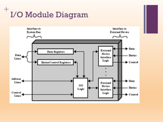
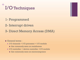
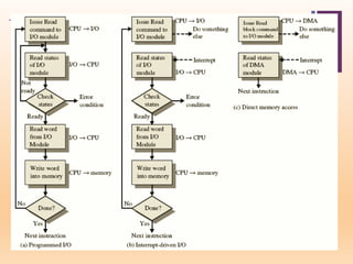
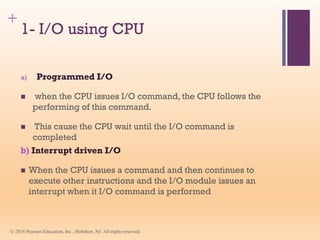
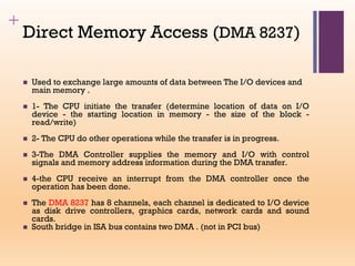
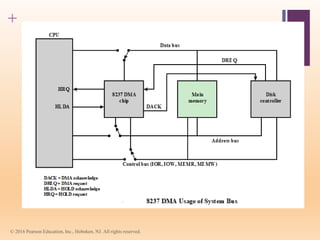
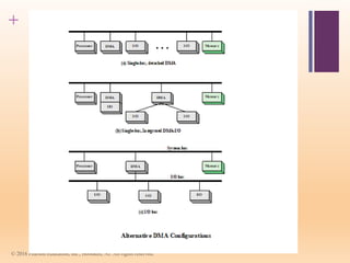
+
William Stallings
Computer Organization
and Architecture
10th Edition
+ Chapter 5
Input-Output
+
Input / Output Function
- Transfer data between the computer (CPU and Memory) and the connected
“peripherals (I/O devices)”.
◼ I/O operations are made by a wide variety of external
devices, simply called “peripherals”, these peripherals are
attached to the computer by a link to an I/O module.
◼ Delivering different amounts of data
◼ At different speeds
◼ In different formats
◼ All peripherals are slower than CPU and RAM
◼ Peripherals need I/O modules through which the exchange
of data can be done.
+
Generic Model of I/O Module
An Interface is required between the CPU bus and an I/O device to arrange
data transfer called “ports (I/O Module) ”
+ External Devices classification :
1-Human readable: suitable for communicating with users.
◼ Screen, printer, keyboard
2- Machine readable, suitable for communicating with
equipment.
◼ Monitoring and control
3- Communication, suitable for communicating with
remote devices.
◼ Modem
◼ Network Interface Card (NIC)
+
The I/O devices
◼ The I/O Device Contains:
◼ 1- buffer: to temporary store data
◼ 2- Logic circuit to:
◼ receive command from I/O module for specific function as Read
data,Write data, disk head position.
◼ Provide the I/O device state as “Ready, Not Ready”.
◼ 3- Transducer: convert electrical data to other form of energy
during output and vise versa during input.
For Example: Keyboard and Monitor
When a user press a key , a corresponding binary
code is generated and transmitted to the computer ,
then same code transmitted to the Monitor to
display.
+
I/O Module Functions
◼ The major function of an I/O module are:
◼ 1- Control & Timing, to coordinate the flow of traffic between internal
resources & external devices.
◼ 2- CPU Communication: Involves command decoding, data, status
reporting, address recognition
◼ 3- Device Communication: Involves commands, status information, and
data
◼ 4- Data Buffering: Performs the needed buffering operation to balance
device and memory speeds
◼ 5- Error Detection: Detects and reports transmission errors
+
I/O Steps (transfer of data between
cpu & external device)
1- CPU asks the I/O module to check the device status
2- The I/O module returns the device status
3- If ready, the CPU requests the transfer of data
4- I/O module gets data from external device (8 or 16 bits,…)
5- The I/O module transfers data to the CPU
+
I/O Module Diagram
+
I/O Techniques
1- Programmed
2- Interrupt driven
3- Direct Memory Access (DMA)
◼ General terms :
◼ I/O channels = I/O processor = I/O module
◼ Are commonly seen on mainframes
◼ I/O controller = device controller =I/O module
◼ Are commonly seen on microcomputers
+
+
1- I/O using CPU
a) Programmed I/O
◼ when the CPU issues I/O command, the CPU follows the
performing of this command.
◼ This cause the CPU wait until the I/O command is
completed
b) Interrupt driven I/O
◼ When the CPU issues a command and then continues to
execute other instructions and the I/O module issues an
interrupt when it I/O command is performed
© 2016 Pearson Education, Inc., Hoboken, NJ. All rights reserved.
+
Example: 82C55 Programmable
Peripheral Interface(continued)
◼ The Control register is loaded
by the CPU to control the
Operation mode:
◼ Mode 0 : programmed I/O
◼ Ports A,B, and C programmed
as buffered input or output .
◼ Mode 1: Interrupt driven I/O
◼ Port A and B programmed as
buffered input or output. Port C
used for handshaking, strobe ,
and Interrupt request signals
+
USING 82C55A with Mode1 operation to
interface with Keyboard/Display
Port A is input from keyboard, PortB is output to display, ½ Port C
is used for handshaking and Interrupt request for the keyboard, the
other half for the display.
+ Direct Memory Access (DMA)
◼ In the previous techniques, interrupt driven and
programmed I/O require active CPU intervention to transfer
data between memory and an I/O module, and any data
transfer must traverse through the cpu, so:
◼ The transfer rate is limited by the speed with which the cpu
can test and service a device.
◼ The CPU is tied up, a number of instructions must be
executed for each I/O transfer.
◼ The DMA module is the solution
◼ In this mode, the I/O module and main memory exchange
data directly, without involving the processor.
+
DMA Function and operation
◼ The DMA involved additional Module (hardware) on the system bus.
◼ The DMA module must use the bus only when the cpu does not need it,
or it forces the cpu to suspend operation temporarily.
◼ When the cpu wishes to read/write a block of data it sends the following
information to the DMA module:
◼ The requested operation Read or Write
◼ The I/O device address
◼ The starting address of memory block for data to be R/W
◼ The amount of data to be transferred
◼ Then the CPU carries on with other work
◼ DMA controller deals with data transfer and sends interrupt when
finished
+
Typical DMA Block Diagram
+
To be continued
+
Direct Memory Access (DMA 8237)
◼ Used to exchange large amounts of data between The I/O devices and
main memory .
◼ 1- The CPU initiate the transfer (determine location of data on I/O
device - the starting location in memory - the size of the block -
read/write)
◼ 2- The CPU do other operations while the transfer is in progress.
◼ 3-The DMA Controller supplies the memory and I/O with control
signals and memory address information during the DMA transfer.
◼ 4-the CPU receive an interrupt from the DMA controller once the
operation has been done.
◼ The DMA 8237 has 8 channels, each channel is dedicated to I/O device
as disk drive controllers, graphics cards, network cards and sound
cards.
◼ South bridge in ISA bus contains two DMA . (not in PCI bus)
+
© 2016 Pearson Education, Inc., Hoboken, NJ. All rights reserved.
+
© 2016 Pearson Education, Inc., Hoboken, NJ. All rights reserved.

chapter5-Input-output.pdf

  • 1.
  • 2.
  • 3.
    + Input / OutputFunction - Transfer data between the computer (CPU and Memory) and the connected “peripherals (I/O devices)”. ◼ I/O operations are made by a wide variety of external devices, simply called “peripherals”, these peripherals are attached to the computer by a link to an I/O module. ◼ Delivering different amounts of data ◼ At different speeds ◼ In different formats ◼ All peripherals are slower than CPU and RAM ◼ Peripherals need I/O modules through which the exchange of data can be done.
  • 4.
    + Generic Model ofI/O Module An Interface is required between the CPU bus and an I/O device to arrange data transfer called “ports (I/O Module) ”
  • 5.
    + External Devicesclassification : 1-Human readable: suitable for communicating with users. ◼ Screen, printer, keyboard 2- Machine readable, suitable for communicating with equipment. ◼ Monitoring and control 3- Communication, suitable for communicating with remote devices. ◼ Modem ◼ Network Interface Card (NIC)
  • 6.
    + The I/O devices ◼The I/O Device Contains: ◼ 1- buffer: to temporary store data ◼ 2- Logic circuit to: ◼ receive command from I/O module for specific function as Read data,Write data, disk head position. ◼ Provide the I/O device state as “Ready, Not Ready”. ◼ 3- Transducer: convert electrical data to other form of energy during output and vise versa during input. For Example: Keyboard and Monitor When a user press a key , a corresponding binary code is generated and transmitted to the computer , then same code transmitted to the Monitor to display.
  • 7.
    + I/O Module Functions ◼The major function of an I/O module are: ◼ 1- Control & Timing, to coordinate the flow of traffic between internal resources & external devices. ◼ 2- CPU Communication: Involves command decoding, data, status reporting, address recognition ◼ 3- Device Communication: Involves commands, status information, and data ◼ 4- Data Buffering: Performs the needed buffering operation to balance device and memory speeds ◼ 5- Error Detection: Detects and reports transmission errors
  • 8.
    + I/O Steps (transferof data between cpu & external device) 1- CPU asks the I/O module to check the device status 2- The I/O module returns the device status 3- If ready, the CPU requests the transfer of data 4- I/O module gets data from external device (8 or 16 bits,…) 5- The I/O module transfers data to the CPU
  • 9.
  • 10.
    + I/O Techniques 1- Programmed 2-Interrupt driven 3- Direct Memory Access (DMA) ◼ General terms : ◼ I/O channels = I/O processor = I/O module ◼ Are commonly seen on mainframes ◼ I/O controller = device controller =I/O module ◼ Are commonly seen on microcomputers
  • 11.
  • 12.
    + 1- I/O usingCPU a) Programmed I/O ◼ when the CPU issues I/O command, the CPU follows the performing of this command. ◼ This cause the CPU wait until the I/O command is completed b) Interrupt driven I/O ◼ When the CPU issues a command and then continues to execute other instructions and the I/O module issues an interrupt when it I/O command is performed © 2016 Pearson Education, Inc., Hoboken, NJ. All rights reserved.
  • 13.
    + Example: 82C55 Programmable PeripheralInterface(continued) ◼ The Control register is loaded by the CPU to control the Operation mode: ◼ Mode 0 : programmed I/O ◼ Ports A,B, and C programmed as buffered input or output . ◼ Mode 1: Interrupt driven I/O ◼ Port A and B programmed as buffered input or output. Port C used for handshaking, strobe , and Interrupt request signals
  • 14.
    + USING 82C55A withMode1 operation to interface with Keyboard/Display Port A is input from keyboard, PortB is output to display, ½ Port C is used for handshaking and Interrupt request for the keyboard, the other half for the display.
  • 15.
    + Direct MemoryAccess (DMA) ◼ In the previous techniques, interrupt driven and programmed I/O require active CPU intervention to transfer data between memory and an I/O module, and any data transfer must traverse through the cpu, so: ◼ The transfer rate is limited by the speed with which the cpu can test and service a device. ◼ The CPU is tied up, a number of instructions must be executed for each I/O transfer. ◼ The DMA module is the solution ◼ In this mode, the I/O module and main memory exchange data directly, without involving the processor.
  • 16.
    + DMA Function andoperation ◼ The DMA involved additional Module (hardware) on the system bus. ◼ The DMA module must use the bus only when the cpu does not need it, or it forces the cpu to suspend operation temporarily. ◼ When the cpu wishes to read/write a block of data it sends the following information to the DMA module: ◼ The requested operation Read or Write ◼ The I/O device address ◼ The starting address of memory block for data to be R/W ◼ The amount of data to be transferred ◼ Then the CPU carries on with other work ◼ DMA controller deals with data transfer and sends interrupt when finished
  • 17.
  • 18.
  • 19.
    + Direct Memory Access(DMA 8237) ◼ Used to exchange large amounts of data between The I/O devices and main memory . ◼ 1- The CPU initiate the transfer (determine location of data on I/O device - the starting location in memory - the size of the block - read/write) ◼ 2- The CPU do other operations while the transfer is in progress. ◼ 3-The DMA Controller supplies the memory and I/O with control signals and memory address information during the DMA transfer. ◼ 4-the CPU receive an interrupt from the DMA controller once the operation has been done. ◼ The DMA 8237 has 8 channels, each channel is dedicated to I/O device as disk drive controllers, graphics cards, network cards and sound cards. ◼ South bridge in ISA bus contains two DMA . (not in PCI bus)
  • 20.
    + © 2016 PearsonEducation, Inc., Hoboken, NJ. All rights reserved.
  • 21.
    + © 2016 PearsonEducation, Inc., Hoboken, NJ. All rights reserved.