Download to read offline
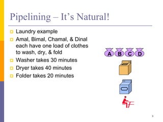
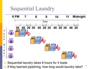
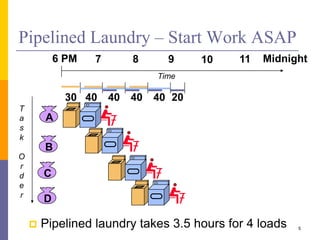
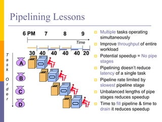
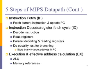
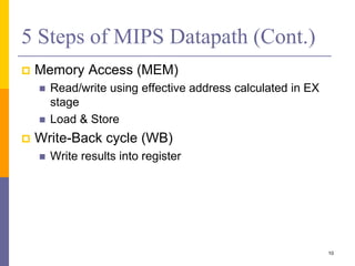
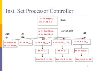
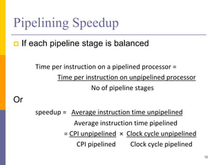
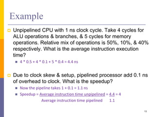
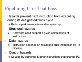
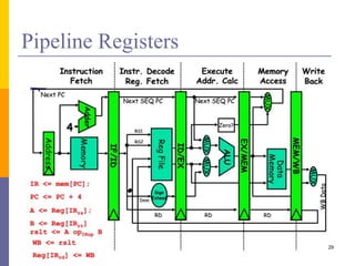
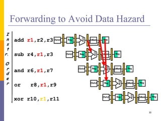
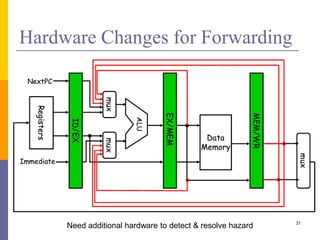
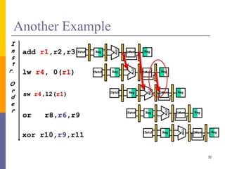
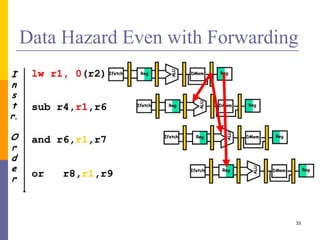
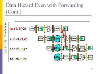
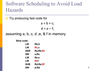
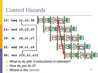
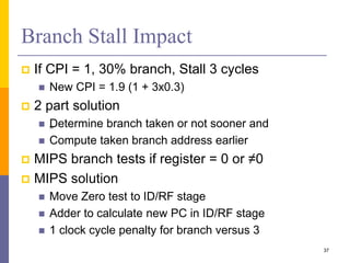
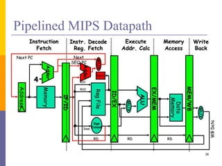
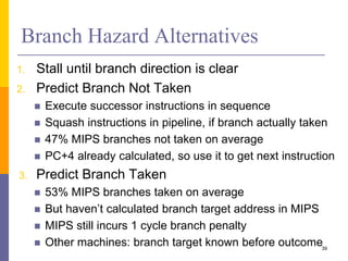
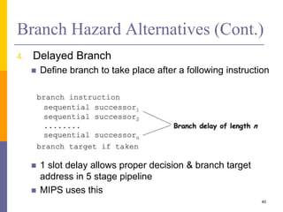

Pipelining is a technique used in computer architecture to overlap the execution of instructions to increase throughput. It works by breaking down instruction execution into a series of steps and allowing subsequent instructions to begin execution before previous ones complete. This allows multiple instructions to be in various stages of completion simultaneously. Pipelining improves performance but introduces hazards such as structural, data, and control hazards that can reduce the ideal speedup if not addressed properly. Control hazards due to branches are particularly challenging to handle efficiently.


![5G Explained! A High Level Overview [Introduction]](https://cdn.slidesharecdn.com/ss_thumbnails/5gexplainedahighleveloverview-260119165306-cc137a3e-thumbnail.jpg?width=640&height=640&fit=bounds)


