Downloaded 229 times


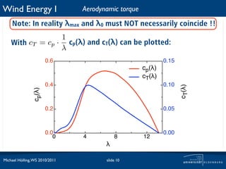
![Wind Energy I Aerodynamic torque
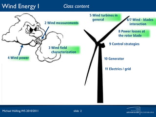
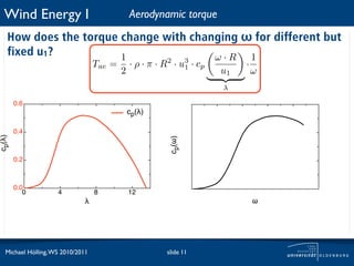
How does the torque change with changing ω for different but
fixed u1? 1 ω·R 1
Tae = · ρ · π · R2 · u3 · cp ·
2 1
u1 ω
λ
u1 = 25m/s
torque [Nm]
cp(!)
! !
Michael Hölling, WS 2010/2011 slide 12](https://image.slidesharecdn.com/19thlesson-111024033720-phpapp02/85/Wind-energy-I-Lesson-9-Control-strategies-12-320.jpg)
![Wind Energy I Aerodynamic torque
How does the torque change with changing ω for different but
fixed u1? 1 ω·R 1
Tae = · ρ · π · R2 · u3 · cp ·
2 1
u1 ω
λ
u1 = 25m/s
u1 = 22m/s
torque [Nm]
cp(!)
! !
Michael Hölling, WS 2010/2011 slide 13](https://image.slidesharecdn.com/19thlesson-111024033720-phpapp02/85/Wind-energy-I-Lesson-9-Control-strategies-13-320.jpg)
![Wind Energy I Aerodynamic torque
How does the torque change with changing ω for different but
fixed u1? 1 ω·R 1
Tae = · ρ · π · R2 · u3 · cp ·
2 1
u1 ω
λ
u1 = 25m/s
u1 = 22m/s
torque [Nm]
u1 = 20m/s
cp(!)
! !
Michael Hölling, WS 2010/2011 slide 14](https://image.slidesharecdn.com/19thlesson-111024033720-phpapp02/85/Wind-energy-I-Lesson-9-Control-strategies-14-320.jpg)
![Wind Energy I Aerodynamic torque
How does the torque change with changing ω for different but
fixed u1? 1 ω·R 1
Tae = · ρ · π · R2 · u3 · cp ·
2 1
u1 ω
λ
u1 = 25m/s
u1 = 22m/s
torque [Nm]
u1 = 20m/s
u1 = 17m/s
cp(!)
! !
Michael Hölling, WS 2010/2011 slide 15](https://image.slidesharecdn.com/19thlesson-111024033720-phpapp02/85/Wind-energy-I-Lesson-9-Control-strategies-15-320.jpg)
![Wind Energy I Aerodynamic torque
How does the torque change with changing ω for different but
fixed u1? 1 ω·R 1
Tae = · ρ · π · R2 · u3 · cp ·
2 1
u1 ω
λ
u1 = 25m/s
u1 = 22m/s
torque [Nm]
u1 = 20m/s
u1 = 17m/s
cp(!)
u1 = 14m/s
! !
Michael Hölling, WS 2010/2011 slide 16](https://image.slidesharecdn.com/19thlesson-111024033720-phpapp02/85/Wind-energy-I-Lesson-9-Control-strategies-16-320.jpg)
![Wind Energy I Aerodynamic torque
How does the torque change with changing ω for different but
fixed u1? 1 ω·R 1
Tae = · ρ · π · R2 · u3 · cp ·
2 1
u1 ω
λ
u1 = 25m/s
u1 = 22m/s
torque [Nm]
u1 = 20m/s
u1 = 17m/s
cp(!)
u1 = 14m/s
u1 = 12m/s
! !
Michael Hölling, WS 2010/2011 slide 17](https://image.slidesharecdn.com/19thlesson-111024033720-phpapp02/85/Wind-energy-I-Lesson-9-Control-strategies-17-320.jpg)
![Wind Energy I Aerodynamic torque
How does the torque change with changing ω for different but
fixed u1? 1 ω·R 1
Tae = · ρ · π · R2 · u3 · cp ·
2 1
u1 ω
λ
u1 = 25m/s
u1 = 22m/s
torque [Nm]
u1 = 20m/s
u1 = 17m/s
cp(!)
u1 = 14m/s
u1 = 12m/s
u1 = 10m/s
! !
Michael Hölling, WS 2010/2011 slide 18](https://image.slidesharecdn.com/19thlesson-111024033720-phpapp02/85/Wind-energy-I-Lesson-9-Control-strategies-18-320.jpg)
![Wind Energy I Aerodynamic torque
How does the torque change with changing ω for different but
fixed u1? 1 ω·R 1
Tae = · ρ · π · R2 · u3 · cp ·
2 1
u1 ω
λ
u1 = 25m/s
u1 = 22m/s
torque [Nm]
u1 = 20m/s
u1 = 17m/s
cp(!)
u1 = 14m/s
u1 = 12m/s
u1 = 10m/s
u1 = 8m/s
! !
Michael Hölling, WS 2010/2011 slide 19](https://image.slidesharecdn.com/19thlesson-111024033720-phpapp02/85/Wind-energy-I-Lesson-9-Control-strategies-19-320.jpg)
![Wind Energy I Aerodynamic torque
How does the torque change with changing ω for different but
fixed u1? 1 ω·R 1
Tae = · ρ · π · R2 · u3 · cp ·
2 1
u1 ω
λ
u1 = 25m/s
u1 = 22m/s
torque [Nm]
u1 = 20m/s
u1 = 17m/s
cp(!)
u1 = 14m/s
u1 = 12m/s
u1 = 10m/s
u1 = 8m/s
u1 = 6m/s
! !
Michael Hölling, WS 2010/2011 slide 20](https://image.slidesharecdn.com/19thlesson-111024033720-phpapp02/85/Wind-energy-I-Lesson-9-Control-strategies-20-320.jpg)
![Wind Energy I Aerodynamic torque
How does the torque change with changing ω for different but
fixed u1? 1 ω·R 1
Tae = · ρ · π · R2 · u3 · cp ·
2 1
u1 ω
λ
u1 = 25m/s
u1 = 22m/s
torque [Nm]
u1 = 20m/s
u1 = 17m/s
cp(!)
u1 = 14m/s
u1 = 12m/s
u1 = 10m/s
u1 = 8m/s
u1 = 6m/s
u1 = 4m/s
! !
Michael Hölling, WS 2010/2011 slide 21](https://image.slidesharecdn.com/19thlesson-111024033720-phpapp02/85/Wind-energy-I-Lesson-9-Control-strategies-21-320.jpg)
![Wind Energy I Aerodynamic torque
How does the torque change with changing ω for different but
fixed u1? 1 ω·R 1
Tae = · ρ · π · R2 · u3 · cp ·
2 1
u1 ω
λ
u1 = 25m/s
u1 = 22m/s
torque [Nm]
u1 = 20m/s
u1 = 17m/s
cp(!)
u1 = 14m/s
u1 = 12m/s
u1 = 10m/s
u1 = 8m/s
u1 = 6m/s
u1 = 4m/s
! !
Tcpmax
Michael Hölling, WS 2010/2011 slide 22](https://image.slidesharecdn.com/19thlesson-111024033720-phpapp02/85/Wind-energy-I-Lesson-9-Control-strategies-22-320.jpg)
![Wind Energy I Aerodynamic torque
How does the torque change with changing ω for different but
fixed u1? 1 ω·R 1
Tae = · ρ · π · R2 · u3 · cp ·
2 1
u1 ω
λ
u1 = 25m/s
u1 = 22m/s
torque [Nm]
u1 = 20m/s
u1 = 17m/s
cp(!)
u1 = 14m/s
u1 = 12m/s
u1 = 10m/s
u1 = 8m/s
u1 = 6m/s
u1 = 4m/s
! !
Tcpmax
Trated power
Michael Hölling, WS 2010/2011 slide 23](https://image.slidesharecdn.com/19thlesson-111024033720-phpapp02/85/Wind-energy-I-Lesson-9-Control-strategies-23-320.jpg)
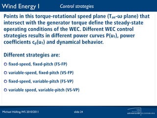
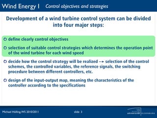
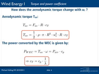
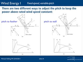
![Wind Energy I Control strategies
The interesting region for the control system is marked in the
red box.
u1 = 25m/s
u1 = 22m/s
torque [Nm]
u1 = 20m/s
u1 = 17m/s
u1 = 14m/s
u1 = 12m/s
u1 = 10m/s
u1 = 8m/s
u1 = 6m/s
u1 = 4m/s
!
Tcpmax
Trated power
Michael Hölling, WS 2010/2011 slide 25](https://image.slidesharecdn.com/19thlesson-111024033720-phpapp02/85/Wind-energy-I-Lesson-9-Control-strategies-25-320.jpg)
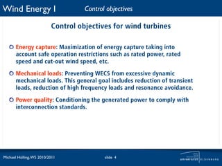
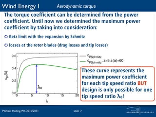
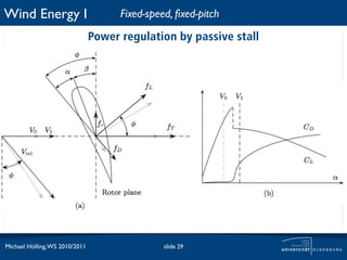
![Wind Energy I Fixed-speed, fixed-pitch
Fixed rotational-speed ω0 is realized by coupling an
asynchronous generator directly to the grid.
0.6
B u1 = 17m/s
cp(!) u1max u1 = 8m/s
C
torque [Nm]
0.4 C u1 = 4m/s
cp(!)
Trated power
D
Tcpmax
0.2
D
B
0.0
12 A Aω
0 4
!
8
u1min !
0
Michael Hölling, WS 2010/2011 slide 26](https://image.slidesharecdn.com/19thlesson-111024033720-phpapp02/85/Wind-energy-I-Lesson-9-Control-strategies-26-320.jpg)
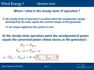
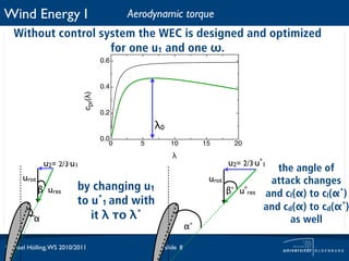
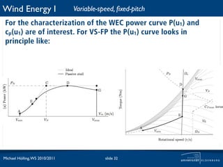
![Wind Energy I Fixed-speed, fixed-pitch
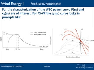
For the characterization of the WEC power curve P(u1) and
cp(u1) are of interest. For FS-FP the P(u1) curve looks in principle
like:
C
u1 = 17m/s
D
u1max u1 = 8m/s
torque [Nm]
P(u1)/Prated
C u1 = 4m/s
Trated power
D
Tcpmax
B
ideal power curve B
power curve
A5 Aω
0 10 15 20 25 30
u1min !
0
u1 [m/s]
Michael Hölling, WS 2010/2011 slide 27](https://image.slidesharecdn.com/19thlesson-111024033720-phpapp02/85/Wind-energy-I-Lesson-9-Control-strategies-27-320.jpg)
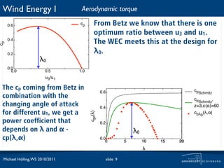
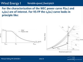
![Wind Energy I Fixed-speed, fixed-pitch
For the characterization of the WEC power curve P(u1) and
cp(u1) are of interest. For FS-FP the cp(u1) curve looks in
principle like:
B u1 = 17m/s
u1max u1 = 8m/s
torque [Nm]
C u1 = 4m/s
cp(u1)
C Trated power
D
Tcpmax
ideal cp
real cp D B
A Aω
0 5 10 15 20 25 30
u1min !
0
u1 [m/s]
Michael Hölling, WS 2010/2011 slide 28](https://image.slidesharecdn.com/19thlesson-111024033720-phpapp02/85/Wind-energy-I-Lesson-9-Control-strategies-28-320.jpg)
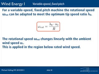

The document discusses control strategies for wind turbines. It begins by outlining the four major steps in developing a wind turbine control system: 1) define clear control objectives, 2) select suitable control strategies, 3) decide how to realize the control strategy, and 4) design the controller. The objectives of wind turbine controls are then defined as maximizing energy capture while preventing excessive mechanical loads and ensuring power quality. The document goes on to explain how the aerodynamic torque on the turbine changes based on wind speed and rotor speed.


