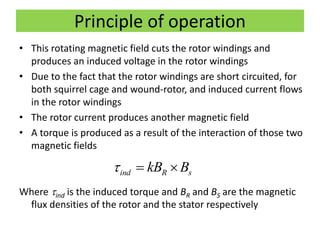
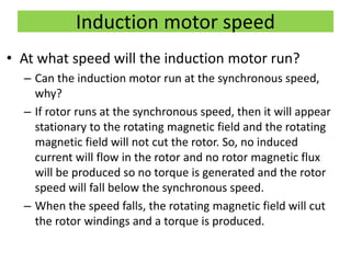
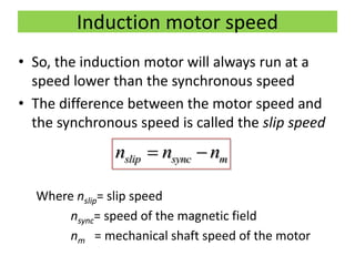
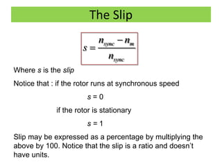
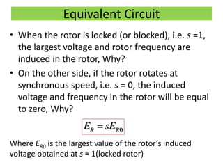
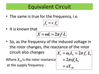
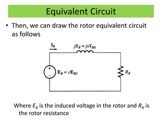
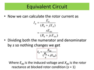
Download as PDF, PPTX
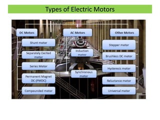
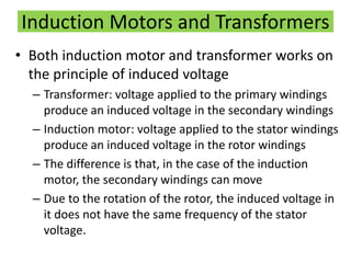
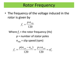
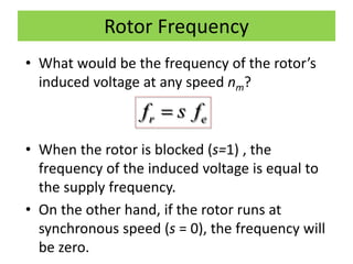
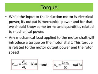
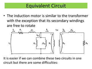
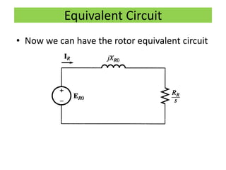
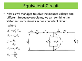
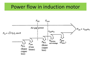
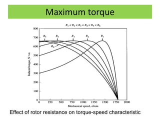
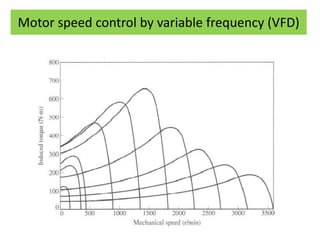
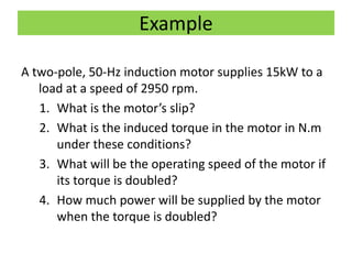
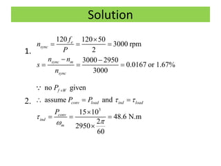
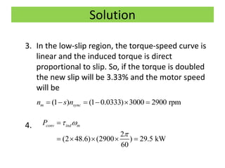

This document discusses induction motors. It begins by explaining the basic construction and operation of 3-phase induction motors, including their squirrel cage and wound rotor types. It then describes how the rotating magnetic field is produced in the stator by the 3-phase currents and how this induces a voltage and current in the rotor. The document discusses how slip occurs and affects rotor speed and frequency. It also covers equivalent circuits, power losses, torque production, and provides an example problem calculating motor parameters.