Downloaded 339 times


![8
Prof MD Dutt HOD Ex Department SRCT ThuakhedaBhopal MP India
Again, manually controlled PST is not fast enough under dynamic conditions. Thyristor
switches can ensure fast controlover discrete (or continuous) values of Á, depending on
the configuration of PST used. Pmax can also be increased by controlling (regulating)
the receiving end voltage of the AC line. When a generator supplies a unity power
factor load (see Fig. 1.1(b)), the maximum power occurs when the load resistance is
equal to the line reactance. It is to be noted that V2 varies with the load and can be
expressed as
V2 =V1cos (θ1-θ2) (1.5)
Substituting (1.5) in (1.1) gives
P = V1² sin[2(θ1-θ2)] (1.6)
2X
By providing dynamic reactive power supportat bus (2) as shown in Fig. (1.6), it is
possible to regulate the bus voltage magnitude. The reactive power (QC) that has to be
injected is given by
QC = V2² - V1V2 cos(θ1-θ2) (1.7)
X
Fig 1.6 Transmission line compensated by controllable reactive power sourceat
receiving end
Comparing eq. (1.6) with (1.1), it can be seen that the maximum power transfer can be
doubled just by providing dynamic reactive power supportat the receiving end of the
transmission line. This is in addition to the voltage supportat the sending end. It is to be
noted that while steady state voltage supportcan be provided by mechanically switched
capacitors, the dynamic voltage supportrequires synchronous condenseror a power
electronic controller suchas Static Var Compensator(SVC) or STATIC synchronous
COMpensator(STATCOM).
4. Analysis of Uncompensated AC Line
A transmission line has distributed circuit parameters. We will be assuming
the line to be symmetric in three phases and operating with balanced
(positive sequence) voltages and currents. Hence it is adequate to consider only a
single phase positive sequence equivalent network of the line (see Fig. 1.7).
In Fig. 1.7, it is assumed that the sending end is connected to a generator and the
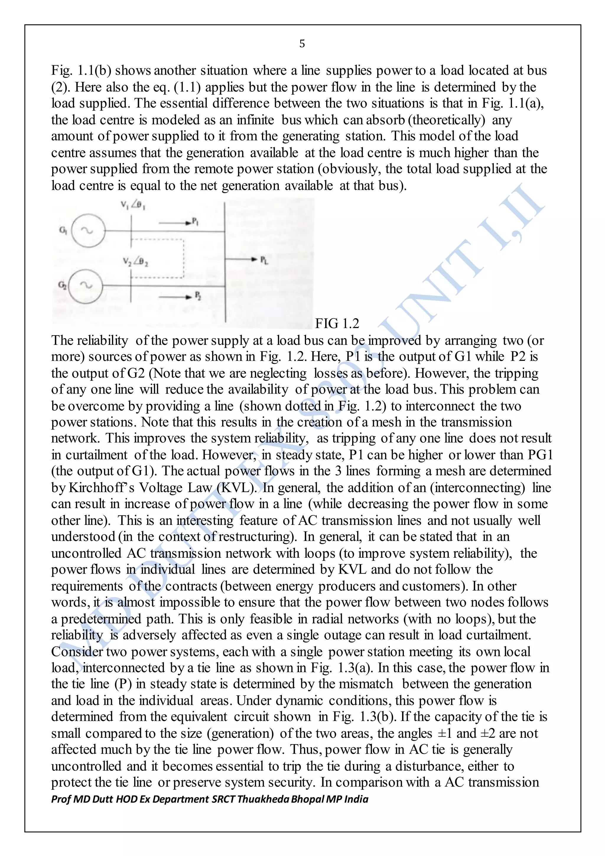
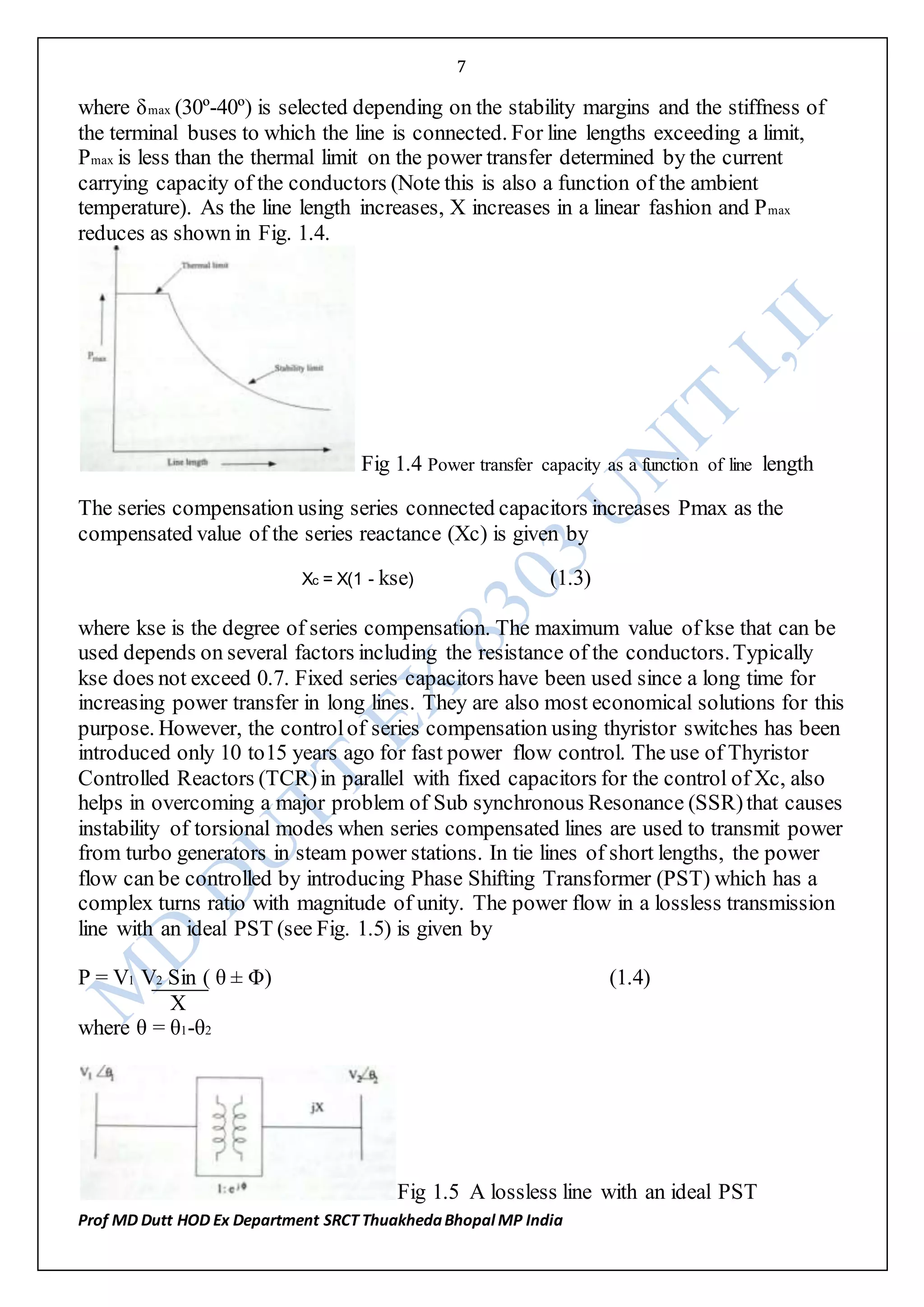
receiving end is connected to a (unity power factor) load. The line has series resistance](https://image.slidesharecdn.com/ex8303unitiii-160609145231/75/RGPV-NOTES-ON-FACTS-EX8303-unit-I-II-8-2048.jpg)


![15
Prof MD Dutt HOD Ex Department SRCT ThuakhedaBhopal MP India
equivalent circuit (in steady state) of the distributed parameter, uncompensated line.
Figure 2.10 shows the equivalent Π circuit of the line.
A = 1 + Y Z
2
= cos θ;
B = Z = jZn sin θ
We can also express Z and Y as
Z = jXn sin θ
θ
Y = j Bn[ tan θ/2]
2 2 θ/2
where Xn = ωld = Znθ the total (nominal) reactance of the line and
Bn = ωcd = θ/Zn is the total (nominal) susceptanceof the line.
For small values of θ; sin θ/θ ≈ 1 and tan θ/2 ≈ θ/2 .
Hence Z ≈ jXn, Y ≈ jBn. With this approximation, this equivalent circuit is called as
the
`nominal' Π circuit of the transmission line.
Note: When we are dealing with single phase equivalent of a balanced
symmetric 3 phase network, the parameters of this circuit are the positive
sequence parameters while the voltages and currents are assumed to contain
only positive sequence components. As a matter of fact, for symmetric
networks with no zero sequence components, the coupled 3 phase network
can be reduced to 3 uncoupled single phase networks. Forexample, from
the simple 3 phase network described by
Va Zs Zm Zm Ia
Vb = Zm Zs Zm Ib
Vc Zm Zm Zs Ic (1.16)](https://image.slidesharecdn.com/ex8303unitiii-160609145231/75/RGPV-NOTES-ON-FACTS-EX8303-unit-I-II-15-2048.jpg)


![25
Prof MD Dutt HOD Ex Department SRCT ThuakhedaBhopal MP India
ref
If BTCR ≤ BL, then a TSC is switched out.
Ref ref
In computing BTCR from BSV C
the effect of leakage reactance of the step down transformer is to be
considered as BSV C is given by
BSV C = - Bσ (BC - BTCR)
(BC - BTCR - Bσ)
= BC - BTCR
(1 - (BC - BTCR)
Bσ (2.16)
where BC is the capacitance of the fixed capacitor or TSC. Bσ »1/Xσ
;Xσ is the leakage reactance of the transformer. If Bσ À BC or- BTCR then,
BSV C ≈ (1 + BC ) BC - [1 +(2BC - BL) ]BTCR
Bσ Bσ
= C1 - C2BTCR (2.17)
BL is the reciprocal of XL and is the maximum value of TCR susceptance.
Neglecting leakage reactance of the transformer, the variation of BTCR with variation of
BSV C for a casewith two identical TSC's is shown in Fig.2.12. This shows that BL (the
rating of TCR) is slightly larger than the rating of either TSC and there is hysteresis in
the operation of the TSC. This is desirable as the switching of a TSC is not well defined
if BC1(susceptanceof a TSC)is exactly equal to BL. If BC1 is greater than BL, then the
operation of the SVC is degraded.
Fig 2.12 Variation VTCR with BSVC for TSC-TCR type SVC
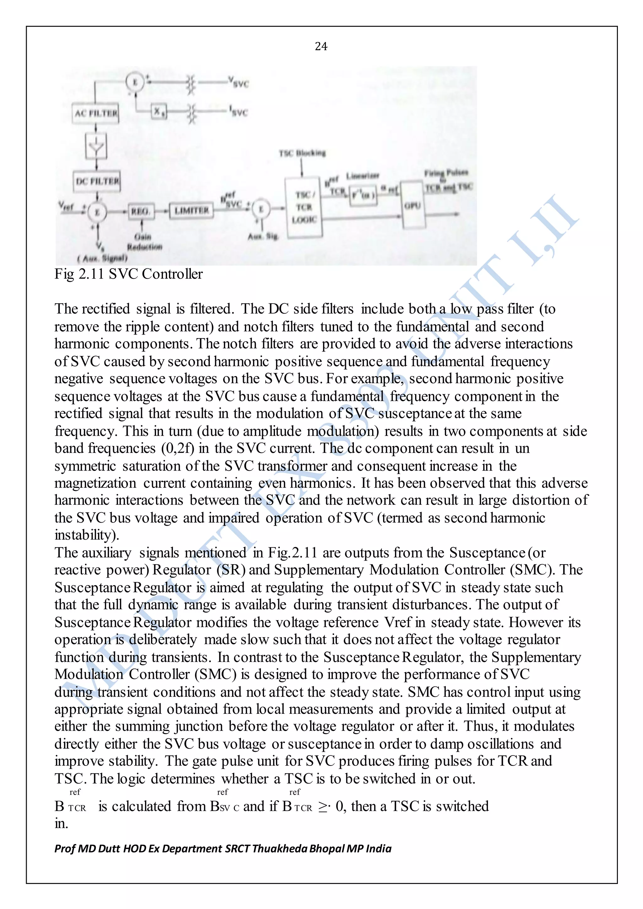
For stability studies, it is not essential to model GPU. In this case, the modelling of the
controller shown in Fig.2.11 can be simplified greatly by also assuming that SVC does
not generate harmonics. The block diagram of the controller in this case is shown in
Fig.2.13. Here the voltage regulator is typically a PI controller as shown in Fig.2.14.](https://image.slidesharecdn.com/ex8303unitiii-160609145231/75/RGPV-NOTES-ON-FACTS-EX8303-unit-I-II-25-2048.jpg)


![31
Prof MD Dutt HOD Ex Department SRCT ThuakhedaBhopal MP India
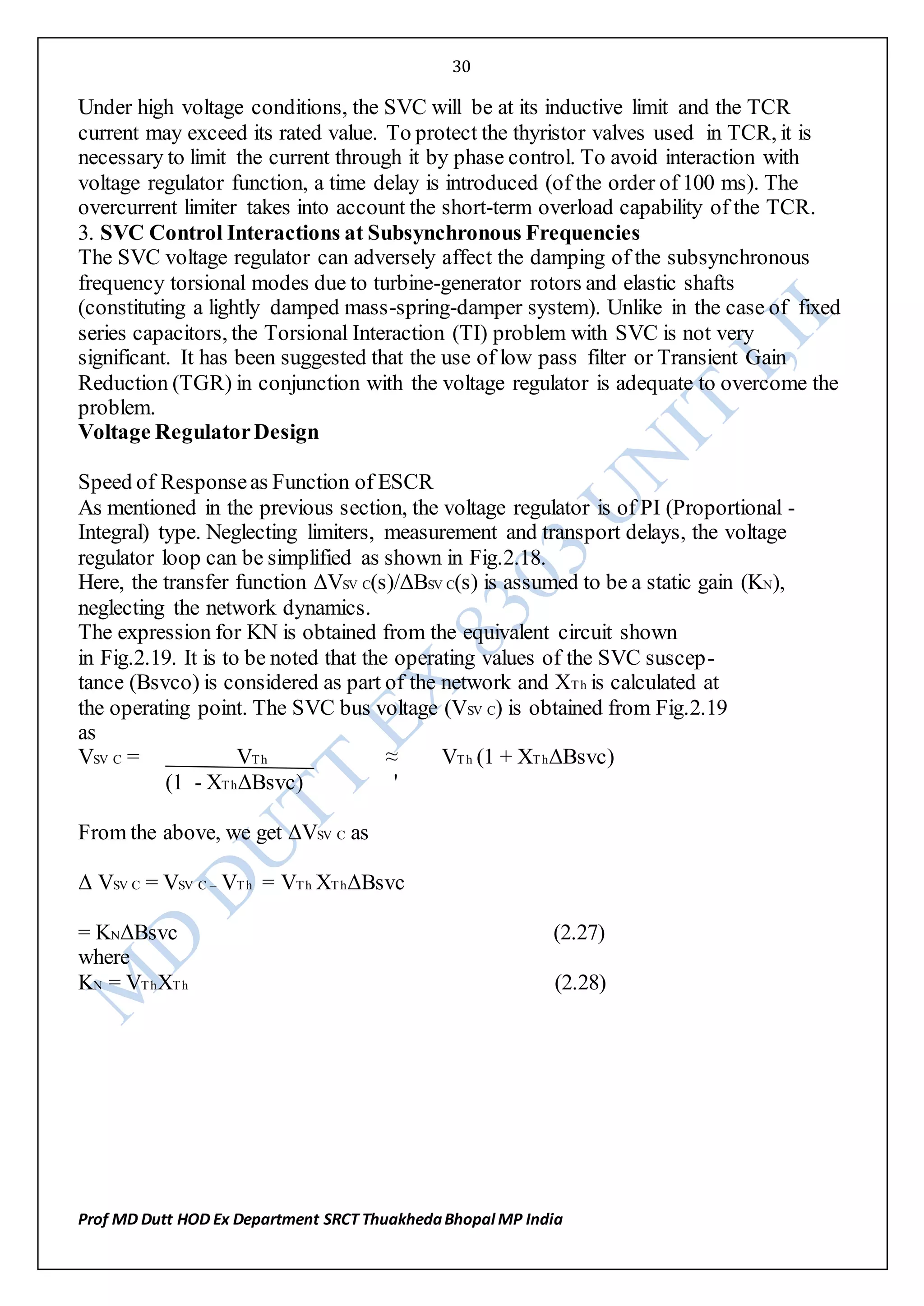
Fig2.18: Simplified system block diagram
Assuming VTh ≈ 1:0, we can also write
KN ≈' XTh = 1 = QSV C
ESCR SC (2.29)
The Effective Short Circuit Ratio (ESCR)is defined as the ratio of the
short circuit level to the rating of the SVC. In defining ESCR it is assumed
that the operating value of BSV C is merged with the network admittance in
computing the short circuit level (in MVA).
Figure 2.19: An equivalent circuit
In Fig. 2.18, the feedback from ISV C is obtained as KIΔBSV C. This
follows from the relation
- XsΔISV C = XsΔBSV C = KIΔBSV C (2.30)
In deriving (2.28) it is assumed that VSV C ≈ 1:0 and BSV C0 = 0 in linearizing Eq. (2.3).
The transfer function of the voltage regulator (GR) is assumed as
GR(s)= KC {1 + sTC} (2.31)
sTC
By selecting TC = Tb and KC = 1
2(KI+KNmax) where KNmax correspondsto
the operating point with lowest value of ESCR, we get a regulator with fast response
with good margin of stability. The closed loop transfer function [Gc(s)]is obtained as
Gc(s)= ΔVSV C(s)
ΔVref (s)
= KN { 1 }](https://image.slidesharecdn.com/ex8303unitiii-160609145231/75/RGPV-NOTES-ON-FACTS-EX8303-unit-I-II-31-2048.jpg)
![32
Prof MD Dutt HOD Ex Department SRCT ThuakhedaBhopal MP India
KN + KI 1 + sTw ( 2.32)
where
Tw = 2(KI + KNmax) Tb
(KI + KN) (2.34)
As KN increases to KNmax, Tw reduces to a value of 2Tb = T/2 (10 ms for the nominal
frequency of 50 Hz). For a step input in ΔVref , the variation in ΔVSV C is given by
ΔVSV C(t) = KN ΔVref (1 - e inverse to the power Tw)
KN + KI (2.35)
The responsetime (to reach 95% of the final value) is 3Tw. The fastest responsetime
for the minimum value of ESCR is 30 ms (for the 50 Hz system).
11 Modelling of SVC
For a detailed study of SVC controlinteractions, it is necessary to perform transient
simulation for which SVC is modelled in detail including the switching of the thyristor
valves in TCR and TSC. The transient network is modelled by differential equations
rather than algebraic equations .
However for stability study it is not necessary to consider the switching of valves and
assume that SVC generates only fundamental current. In addition, the network
transients are neglected and represented by algebraic equations of the type:
[Y ]V = I (2.36)
With these simplifications, SVC can be modelled as a variable susceptance
which is the output of the control system as shown in Fig.2.13. If SMC is
a part of the SVC controller, it should be included in the model. However,
susceptanceregulator, gain supervisor and the protective functions can be
neglected in the model.
For the preliminary studies, it is adequate to ignore the dynamics of SVC control
(without SMC) and assume that the SVC is described by its steady state control
characteristics. If SMC is present, it can be modeled as shown in Fig. 2.17.
Steady State Model of SVC
The steady state control characteristics are modelled by an equivalent circuit
shown in Fig. 2.32. This shows a complex voltage source ÉSV C in series with
a reactance XSV C. The losses in the SVC are neglected. The values of ^ESV C
and XSV C are given below for the SVC operating in (i) the control range,
(ii) capacitive limit and (iii) inductive limit
(i) Control Range
ÉSV C = Vref ∟Øsvc (2.37)](https://image.slidesharecdn.com/ex8303unitiii-160609145231/75/RGPV-NOTES-ON-FACTS-EX8303-unit-I-II-32-2048.jpg)

![34
Prof MD Dutt HOD Ex Department SRCT ThuakhedaBhopal MP India
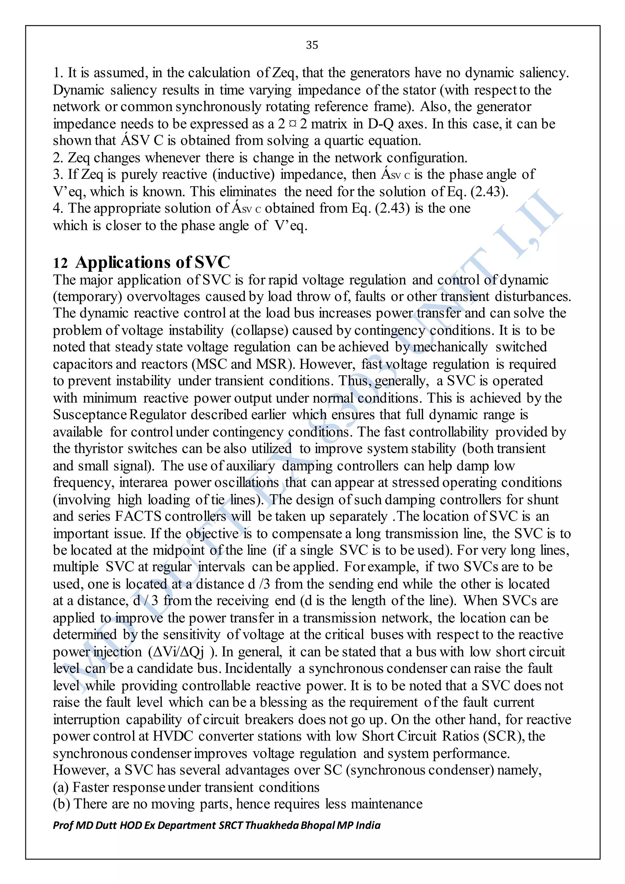
constant, Zeq remains constant. Zeq is calculated as the impedance of the network seen
at the SVC terminals when all the sources in the network are removed ( the voltage
sources are shorted and the current sources are open circuited). V’eq is found as the
SVC terminal voltage with the SVC current zero. V’eq varies with time as the
generator voltages vary during a disturbance. From Fig.2.33, the SVC current can be
computed as
ÌSV C = V’eq - ÉSV C
Zeq + jXSV C (2.42)
Fig 2.33: SVC connected to Thevenin equivalent
If ÉSV C = 0:0+j0:0,the solution is straight forward. However, in the control
range, the angle ØSV C needs to be known to apply Eq.(2.42).
It can be shown that tan ØSV C is obtained as the solution of a
quadratic equation given by
a tan² ØSV C + b tan ØSV C + c = 0 (2.43)
where
a = x² - z² sin²α;
b = - 2xy;
c = y² -¡ z² sin² α
x = Re[(1 - Á)V’eq] ; y = Im[([(1 - Á)V’eq]
z = Á Vref
Á = A∟α = Zeq
Zeq + jXSV C
Network Solution
The network solution is carried out in two steps. In the first step, the voltage
solution is obtained by putting ÌSV C = 0. The voltage calculated at the SVC
bus, at the end of the first step is same as V’eq. The knowledge of V’eq and Zeq
(which has been calculated in advance and stored) enables the computation
of ÌSV C from Eq. (2.42) and Eq.(2.43) (if required). The network is solved again with
the injection of ÌSV C at the SVC bus (all other sources put equal to zero).The second
solution requires minimal computations as the current vector is sparse.
The voltage at all the buses are obtained from the addition (superposition) of the two
sets of the voltage calculated in the two network solutions.
Remarks](https://image.slidesharecdn.com/ex8303unitiii-160609145231/75/RGPV-NOTES-ON-FACTS-EX8303-unit-I-II-34-2048.jpg)

![37
Prof MD Dutt HOD Ex Department SRCT ThuakhedaBhopal MP India
Consider a simplified system as seen from the terminals of the static
shunt compensator (shown in Fig. 2.20).
Figure 2.20: A simplified representation for interaction with network resonance
The positive sequence driving point impedance ZTh(s) in the Laplace domain, at the SVC bus is given
by
ZTh(s) = (R + sL)
(s²LC + sRC + 1) (2.44)
The equations in the D-Q (synchronously rotating reference frame)
variables are given by
VSD(s) = ZDD(s) ZDQ(s ) IRD(s)
VSQ(s) ZQD(s) ZQQ(s) IRQ(s) (2.45)
where
ZDD(s) = ZQQ(s) = ZTh(s + jωט) + ZTh (s - jωט)
2 (2.46)
ZQD(s) = -ZDQ(s) = j ZTh (s + jωט) -ZTh ZTh (s - jωט)
2
= -Im[ZTh (s + j ωט)] (2.47)
The D-Q components of the SVC bus voltage (VS) and current (IR) are
shown in Fig. 2.21.
Fig 2.21: A phasordiagram
From Fig.(2.21), we have
VSD = VS sin θ; VSQ = VScos θ (2.48)](https://image.slidesharecdn.com/ex8303unitiii-160609145231/75/RGPV-NOTES-ON-FACTS-EX8303-unit-I-II-37-2048.jpg)
![38
Prof MD Dutt HOD Ex Department SRCT ThuakhedaBhopal MP India
From Eq. (2.48), we get
ΔVS = sin θטΔVSD + cos θטΔVSQ (2.49)
If we assume that the current injected by the SVC is purely reactive, we
have
IRQ = -R sin θ; IRD = IR cos θ (2.50)
From Eq. (2.50), we get
ΔIRD(s) = cos θט IRo - sin θט
ΔIRQ(s) - sin θ ט ΔIR(s) + - cos θט Δθ(s)
= cos θט
-sin θט ΔIR(s) ( 2.51)
We have assumed IRo = 0 as before. Linearizing Eq. (2.45), and substituting
from (2.50) and (2.51), we get
ΔVS(s) = ZQD(s) = KN(s)
ΔIR(s) D(s) (2.52)
where N(s) and D(s) are the numerator and the denominator polynomials,
where
K = (ωטL)ωη²
D(s) = [s + σ + j(ω - ωט)][s + σ - j ω - ωט)] [s + σ + j(ω +- ωט)][s + σ - j(ω + ωט)]
N(s) = s² + 2R s + R²+ ω²ט - 1
L L² LC
σ = R ω = √ ωη² - σ² , ωη = 1
2L √LC
When R ≈ 0, then
N(s) ≈ s² + ω²ט-- 1
LC
= s² + ω²ט - ωη² (2.53)
Since ωט > ωט, the numerator polynomial N(s) has a pair of real zeros given
by](https://image.slidesharecdn.com/ex8303unitiii-160609145231/75/RGPV-NOTES-ON-FACTS-EX8303-unit-I-II-38-2048.jpg)
![39
Prof MD Dutt HOD Ex Department SRCT ThuakhedaBhopal MP India
s = ± √ ωη² - ω²ט (2.54)
Thus, the transfer function ΔVs(s)
ΔIr(s) is a non-minimum phase type with a zero
in the R.H.P. (on the positive real axis). The controlof plants with non-
minimum phase type is always problematic and requires compensation to enable the use
of P-I controlwith high gains.
Remarks
1. The four poles of the transfer function ΔVS(s) all lie in the L.H.P. and are given by
ΔIR(s)
p1, p2 = -σ ± j(ω - ωט); p3, p4 = -σ ± j(ω + ωט)
where -σ ± jω are the poles of the impedance function ZTh(s).
3. For R ≈ 0, it can be shown that the transfer function reduces to
ΔVS(s) ≈ ωטLωη² (s²- ωη² + ωט²)
ΔIR(s) [ s²-(ωη - ωט) ²] [s²+ (ωη + ωט)²] (2.55)
Substituting for s = 0, we get
ΔVS= -XTh (2.56)
ΔIR
where
XTh =ωL = ωטL ωη ²
1 - ωט²LC ωη² - ω²ט
is the reactance of the parallel combination of L and C, evaluated at the
operating frequency ωט Eq. (2.56) can be compared with Eq. (2.27) as
IR = ISV C = -BSV CVSV C. As it is assumed that IRo = 0, VSV C0= VTh
(Note that the subscript`o' indicates the operating value of the variable).
The adverse control interactions with network resonance are functions of the ESCR and
the operating point. The lower value of ESCR and the SVC operation at capacitive
region worsen the control stability problem. The controller gain needs to be reduced to
overcome the problem. This may not be practical as the responseof SVC needs to be
fast at lower values of ESCR. One of the solution suggested in is to provide a
compensator in cascadewith the voltage regulator, that rejects the complement of the](https://image.slidesharecdn.com/ex8303unitiii-160609145231/75/RGPV-NOTES-ON-FACTS-EX8303-unit-I-II-39-2048.jpg)


1. The document discusses issues related to bulk power transmission and the need for Flexible AC Transmission Systems (FACTS) controllers to enhance system controllability and power transfer capacity. It covers topics such as analysis of uncompensated transmission lines, passive reactive power compensation, and voltage control using static var compensators. 2. It provides an overview of various FACTS controllers and their benefits in improving power flow control capability, transient stability, and steady-state voltage stability of power systems. Specific controllers discussed include thyristor controlled series capacitors, static var compensators, and phase shifting transformers. 3. The document presents models and equations for analyzing power flow in AC transmission lines and explains how FACTS controllers can